EP1038824A2 - Chain elevator - Google Patents
Chain elevator Download PDFInfo
- Publication number
- EP1038824A2 EP1038824A2 EP00660055A EP00660055A EP1038824A2 EP 1038824 A2 EP1038824 A2 EP 1038824A2 EP 00660055 A EP00660055 A EP 00660055A EP 00660055 A EP00660055 A EP 00660055A EP 1038824 A2 EP1038824 A2 EP 1038824A2
- Authority
- EP
- European Patent Office
- Prior art keywords
- chain
- elevating
- chain gear
- gear
- driven
- Prior art date
- Legal status (The legal status is an assumption and is not a legal conclusion. Google has not performed a legal analysis and makes no representation as to the accuracy of the status listed.)
- Withdrawn
Links
- 230000003028 elevating effect Effects 0.000 claims abstract description 76
- 230000008878 coupling Effects 0.000 claims description 6
- 238000010168 coupling process Methods 0.000 claims description 6
- 238000005859 coupling reaction Methods 0.000 claims description 6
- 230000005540 biological transmission Effects 0.000 description 3
- 230000000694 effects Effects 0.000 description 2
Images
Classifications
-
- B—PERFORMING OPERATIONS; TRANSPORTING
- B66—HOISTING; LIFTING; HAULING
- B66D—CAPSTANS; WINCHES; TACKLES, e.g. PULLEY BLOCKS; HOISTS
- B66D3/00—Portable or mobile lifting or hauling appliances
- B66D3/18—Power-operated hoists
- B66D3/26—Other details, e.g. housings
Definitions
- the invention relates to a chain elevator which comprises an elevating chain made up of links attached to each other, whereby the planes formed by adjacent links are primarily at a 90° angle in relation to each other and which chain has a fixed end; an elevating element having a driven chain gear arranged to it, the elevating chain being led to couple with the driven chain gear from the fixing point of the fixed end of the elevating chain located above the driven chain gear in such a manner that the elevating element hangs on the elevating chain; and a driving chain gear located above the driven chain gear, the elevating chain being led to couple with the driving chain gear from the driven chain gear, whereby the plane formed by each elevating chain link in said coupling is substantially at a 45° angle in relation to the shaft of the driving chain gear.
- the invention also relates to a chain elevator which comprises an elevating chain made up of links attached to each other, whereby the planes formed by adjacent links are primarily at a 90° angle in relation to each other and which chain has a fixed end; an elevating element having a driven chain gear arranged to it, the elevating chain being led to couple with the driven chain gear from the fixing point of the fixed end of the elevating chain located above the driven chain gear in such a manner that the elevating element hangs on the elevating chain, whereby the plane formed by every second link of the elevating chain in said coupling is substantially parallel with the shaft of the driven chain gear and the plane formed by every other link is substantially perpendicular with said shaft; and a driving chain gear located above the driven chain gear, the elevating chain being led to couple with the driving chain gear from the driven chain gear.
- a conventional chain elevator i.e. the one described last in the above, is one in which every second chain link plane is, when coupled with both the (freely rotating) driven chain gear and the driving chain gear (drive gear), parallel with the shaft of the chain gear and every other chain link perpendicular with it.
- every second link is capable of transmitting the power of the driving chain gear to the elevating chain.
- a more advanced solution i.e. the one described first in the above, is a 45° chain drive in which the elevating chain runs through the chain gears so that the plane of each link is always at an approximately 45° angle in relation to the chain gear shafts.
- the 45° chain drive provides, for instance, the following advantages: all links in the elevating chain participate in power transmission when coupled with the driving chain gear and the polygon effect (i.e. the variation in elevating speed and force caused by the polygon-form of the chain gear) lessens.
- a 4-pocket chain gear in a 45° chain drive for instance, achieves the same properties as an 8-pocket chain gear in a conventional chain drive.
- the 45° chain drive also has significant drawbacks, because the forces between the elevating chain and the driven chain gear are extremely disadvantageous for both the chain and the chain gear. Therefore, both wear quickly and in particular when used in a drive which has the same chain length all the time and consequently the same location in the chain runs repeatedly through the driven chain gear. In such a case, there is an actual danger of a chain break.
- the driven chain gear and the passage of the elevating chain through it is implemented as in a conventional chain elevator, in which every second chain link is horizontal in relation to the shaft of the driven chain gear and every other link is perpendicular in relation to it, while the driving chain gear and the passage of the elevating chain through it is as in a 45° chain drive.
- every second chain link is horizontal in relation to the shaft of the driven chain gear and every other link is perpendicular in relation to it
- the driving chain gear and the passage of the elevating chain through it is as in a 45° chain drive.
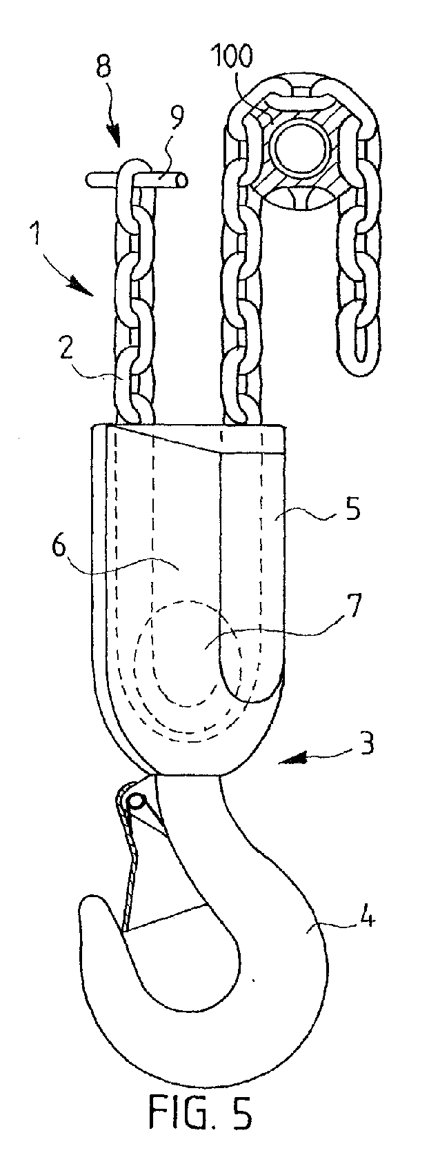
- FIGS 1 and 2 show a conventional chain elevator which comprises an elevating chain 1 made up of links 2 attached to each other, whereby the planes formed by adjacent links 2 are primarily at a 90° angle in relation to each other; an elevating element 3 which comprises a lifting hook 4 and a related hook casing 5 inside which there is a cavity 6 into which a driven chain gear 7 is mounted, the elevating chain 1 being led to couple with the driven chain gear 7 from the fixing point 9 of the fixed end 8 of the elevating chain 1 located above the driven chain gear 7 in such a manner that the elevating element 3 hangs on the elevating chain 1; and a driving chain gear 10 located above the driven chain gear 7, the elevating chain 1 being led to couple with the driving chain gear from the driven chain gear 7.
- the plane formed by every second link 2 of the elevating chain 1 coupled with the chain gears 7 and 10 is substantially parallel with the shaft 7a, 10a of the chain gear 7, 10 being used, and the plane formed by every other link 2 is substantially perpendicular with said shaft.
- the chain elevator having a 45° chain gear shown in Figures 3 and 4 differs from the conventional chain elevator shown in Figures 1 and 2 mainly only in that the plane formed by each elevating chain 1 link 2 coupled with the chain gears 70 and 100 is substantially at a 45° angle in relation to the shafts 70a, 100a of the chain gears 70, 100.
- each link 2 of the elevating chain 1 transmits power when in the pockets 110 of the chain gear 70, 100.
- Another difference with the conventional chain gear 7, 10 is that the chain gear 70, 100 can be made smaller in diameter, which provides the advantages stated above.
- the chain elevator of the invention shown in Figures 5 and 6 differs from the prior art elevators described above in that the fixing point 9 of the fixed end 8 of the elevating chain 1 is moved aside from the rotating plane A of the driving chain gear 100 so that the shaft 7a of the driven chain gear 7 is substantially at a 45° angle in relation to the shaft 100a of the driving chain gear 100 in the direction of view defined by the chain section between the driven and the driving chain gear 7, 100 (i.e.
- the chain section between the fixed end 8 of the elevating chain and the driven chain gear is substantially parallel with the chain section between the driven and driving chain gear 7, 100, whereby the forces affecting the chain gears 7, 100 can be made as advantageous (small) as possible.
Landscapes
- Engineering & Computer Science (AREA)
- Mechanical Engineering (AREA)
- Lift-Guide Devices, And Elevator Ropes And Cables (AREA)
- Load-Engaging Elements For Cranes (AREA)
- Types And Forms Of Lifts (AREA)
Abstract
Description
Claims (6)
- A chain elevator comprisingcharacterized in that the fixing point (9) of the fixed end of the elevating chain is moved aside from the rotating plane (A) of the driving chain gear (100) so that the shaft (7a) of the driven chain gear (7) is substantially at a 45° angle in relation to the shaft (100a) of the driving chain gear (100) in the direction of view defined by the chain section between the driven and the driving chain gear, and that the plane formed by every second link (2) of the elevating chain coupled with the driven chain gear (7) is substantially parallel with the shaft (7a) of the driven chain gear (7) and the plane formed by every other link (2) is substantially perpendicular with said shaft.an elevating chain (1 ) made up of links (2) attached to each other, whereby the planes formed by adjacent links are primarily at a 90° angle in relation to each other, and which chain has a fixed end (8),an elevating element (3) having a driven chain gear (7) arranged to it, the elevating chain (1 ) being led to couple with the driven chain gear from the fixing point (9) of the fixed end of the elevating chain located above the driven chain gear in such a manner that the elevating element hangs on the elevating chain, anda driving chain gear (100) located above the driven chain gear (7), the elevating chain (1 ) being led to couple with the driving chain gear from the driven chain gear, whereby the plane formed by each elevating chain link (2) in said coupling is substantially at a 45° angle in relation to the shaft (100a) of the driving chain gear,
- A chain elevator as claimed in claim 1, characterized in that the elevating element (3) comprises a lifting hook (4) and a related hook casing (5) inside which there is a cavity (6) into which the driven chain gear (7) is arranged.
- A chain elevator as claimed in claim 1 or 2, characterized in that the chain section between the fixed end (8) of the elevating chain and the driven chain gear (7) is substantially parallel with the chain section between the driven and driving chain gear (7, 100).
- A chain elevator comprisingcharacterized in that the fixing point (9) of the fixed end of the elevating chain is moved aside from the rotating plane (A) of the driving chain gear (100) so that the shaft (7a) of the driven chain gear (7) is substantially at a 45° angle in relation to the shaft (100a) of the driving chain gear (100) in the direction of view defined by the chain section between the driven and the driving chain gear, and that the plane formed by each link (2) of the elevating chain (1) coupled with the driving chain gear (100) is substantially at a 45° angle in relation to the shaft (100a) of the driving chain gear (100).an elevating chain (1) made up of links (2) attached to each other, whereby the planes formed by adjacent links are primarily at a 90° angle in relation to each other, and which chain has a fixed end (8),an elevating element (3) having a driven chain gear (7) arranged to it, the elevating chain (1 ) being led to couple with the driven chain gear from the fixing point (9) of the fixed end of the elevating chain located above the driven chain gear in such a manner that the elevating element hangs on the elevating chain, whereby the plane formed by every second link (2) of the elevating chain in said coupling is substantially parallel with the shaft (7a) of the driven chain gear (7) and the plane formed by every other link is substantially perpendicular with said shaft, anda driving chain gear (100) located above the driven chain gear (7), the elevating chain (1 ) being led to couple with the driving chain gear from the driven chain gear,
- A chain elevator as claimed in claim 4, characterized in that the elevating element (3) comprises a lifting hook (4) and a related hook casing (5) inside which there is a cavity (6) into which the driven chain gear (7) is arranged.
- A chain elevator as claimed in claims 4 or 5, characterized in that the chain section between the fixed end (8) of the elevating chain and the driven chain gear (7) is substantially parallel with the chain section between the driven and driving chain gear (7, 100).
Applications Claiming Priority (2)
| Application Number | Priority Date | Filing Date | Title |
|---|---|---|---|
| FI990681A FI106304B (en) | 1999-03-26 | 1999-03-26 | Kedjelyftanordning |
| FI990681 | 1999-03-26 |
Publications (2)
| Publication Number | Publication Date |
|---|---|
| EP1038824A2 true EP1038824A2 (en) | 2000-09-27 |
| EP1038824A3 EP1038824A3 (en) | 2003-09-03 |
Family
ID=8554294
Family Applications (1)
| Application Number | Title | Priority Date | Filing Date |
|---|---|---|---|
| EP00660055A Withdrawn EP1038824A3 (en) | 1999-03-26 | 2000-03-22 | Chain elevator |
Country Status (4)
| Country | Link |
|---|---|
| US (1) | US6199830B1 (en) |
| EP (1) | EP1038824A3 (en) |
| JP (1) | JP2000309493A (en) |
| FI (1) | FI106304B (en) |
Families Citing this family (4)
| Publication number | Priority date | Publication date | Assignee | Title |
|---|---|---|---|---|
| ES2208471T3 (en) * | 2001-01-26 | 2004-06-16 | Univ.-Prof. Dipl.-Ing. Dr. Techn. Jorg Oser O. | CHAIN TRANSMISSION PROVIDED WITH A POLYGON CHAIN WHEEL. |
| DE202007002119U1 (en) * | 2007-02-08 | 2008-06-26 | Bucyrus Dbt Europe Gmbh | Sprocket for chain drives |
| US8851455B2 (en) | 2012-09-13 | 2014-10-07 | Ventra Group, Inc. | Reel assembly for chain hoist |
| EP4292973A3 (en) * | 2021-09-23 | 2024-03-13 | Pewag Austria GmbH | Chain drive with double chain wheel, stop device therefor, and chain drive system |
Family Cites Families (16)
| Publication number | Priority date | Publication date | Assignee | Title |
|---|---|---|---|---|
| DE556782C (en) * | 1932-08-13 | Schubert & Salzer Maschinen | Link chain for half cross drive | |
| US616936A (en) * | 1899-01-03 | Sprocket wheel and chain | ||
| US393491A (en) * | 1888-11-27 | Drive-chain | ||
| US225953A (en) * | 1880-03-30 | Differential-pulley apparatus | ||
| US662768A (en) * | 1900-03-12 | 1900-11-27 | Paul Louis Crowe | Sprocket-wheel for use on chain grates. |
| US1035030A (en) * | 1909-11-22 | 1912-08-06 | Edward Y Moore | Hoist. |
| US1130420A (en) * | 1914-07-13 | 1915-03-02 | Edward Y Moore | Hoisting mechanism. |
| GB144655A (en) * | 1919-06-12 | 1920-12-23 | Smidth & Co As F L | Improvements in chain wheels |
| US2321702A (en) * | 1942-11-19 | 1943-06-15 | Samuel M Renkin | Chain wheel |
| US2613546A (en) * | 1950-04-04 | 1952-10-14 | Jorgensen Aage Erland | Drive chains and chain drives adapted to use said chains |
| US2772072A (en) * | 1954-01-04 | 1956-11-27 | Columbus Mckinnon Chain Corp | Hoist |
| US3362239A (en) * | 1965-11-04 | 1968-01-09 | Russell F. Kaye | Oblique lay idler wheel |
| US3415135A (en) * | 1965-12-06 | 1968-12-10 | Columbus Mckinnon Corp | Oblique lay pocket wheel |
| US4108014A (en) * | 1976-12-29 | 1978-08-22 | Columbus Mckinnon Corporation | Oblique lay sprocket wheel and chain construction |
| NL7904559A (en) * | 1979-06-11 | 1980-12-15 | Kaak Metaalfab B V | DRIVE WHEEL FOR A CHAIN. |
| US4459124A (en) * | 1980-10-31 | 1984-07-10 | Newton Alan R | Drive chain |
-
1999
- 1999-03-26 FI FI990681A patent/FI106304B/en not_active IP Right Cessation
-
2000
- 2000-03-22 EP EP00660055A patent/EP1038824A3/en not_active Withdrawn
- 2000-03-24 US US09/534,382 patent/US6199830B1/en not_active Expired - Fee Related
- 2000-03-27 JP JP2000090711A patent/JP2000309493A/en active Pending
Also Published As
| Publication number | Publication date |
|---|---|
| FI106304B (en) | 2001-01-15 |
| JP2000309493A (en) | 2000-11-07 |
| EP1038824A3 (en) | 2003-09-03 |
| FI990681A0 (en) | 1999-03-26 |
| US6199830B1 (en) | 2001-03-13 |
| FI990681A7 (en) | 2000-09-27 |
Similar Documents
| Publication | Publication Date | Title |
|---|---|---|
| KR101265565B1 (en) | Composite v-belt transmission system combining the friction transmission with the mesh transmission | |
| CA2646872A1 (en) | Snow blower belt driven transmission | |
| CA2449472A1 (en) | A building panel | |
| US6199830B1 (en) | Chain elevator | |
| AU2018351932A1 (en) | Elevator system comprising deflecting elements having different groove geometries | |
| WO2001040678A3 (en) | Gearbox | |
| PL202370B1 (en) | V−belt system | |
| EP1054175A3 (en) | Power transmission mechanism | |
| KR20230088139A (en) | A deceleration apparatus and a vertical pump having the same | |
| CN208381203U (en) | A kind of synchronous belt of high-intensity and high-tenacity | |
| CN210661228U (en) | Multi-gear transmission with power takeoff structure | |
| KR200248087Y1 (en) | Chain driving means of round shaped stick | |
| CN211686859U (en) | A slender shaft support transmission | |
| CN213899661U (en) | Clutch device and hoisting equipment comprising same | |
| CN101424164A (en) | Power swivel for top-drive device | |
| CN216141184U (en) | Anti-falling type lifting feeder | |
| CN111517071B (en) | Plate chain bucket type elevator | |
| KR20110113979A (en) | Chain coupling | |
| EP0663369B1 (en) | Hoisting device | |
| CN219159442U (en) | Reduction gear with backstop mechanism | |
| SU1143902A1 (en) | Engageable clutch | |
| SU1759784A1 (en) | Hand winch | |
| KR102136279B1 (en) | Chain belt with pin having oil groove and continuously variable transmission having the chain belt | |
| SU1208227A1 (en) | Feed mechanism of excavating cutter-loader | |
| CN211496241U (en) | Power transmission mechanism |
Legal Events
| Date | Code | Title | Description |
|---|---|---|---|
| PUAI | Public reference made under article 153(3) epc to a published international application that has entered the european phase |
Free format text: ORIGINAL CODE: 0009012 |
|
| AK | Designated contracting states |
Kind code of ref document: A2 Designated state(s): AT BE CH CY DE DK ES FI FR GB GR IE IT LI LU MC NL PT SE |
|
| AX | Request for extension of the european patent |
Free format text: AL;LT;LV;MK;RO;SI |
|
| PUAL | Search report despatched |
Free format text: ORIGINAL CODE: 0009013 |
|
| AK | Designated contracting states |
Kind code of ref document: A3 Designated state(s): AT BE CH CY DE DK ES FI FR GB GR IE IT LI LU MC NL PT SE |
|
| AX | Request for extension of the european patent |
Extension state: AL LT LV MK RO SI |
|
| 17P | Request for examination filed |
Effective date: 20030930 |
|
| 17Q | First examination report despatched |
Effective date: 20031024 |
|
| AKX | Designation fees paid |
Designated state(s): CH DE FR GB IT LI |
|
| STAA | Information on the status of an ep patent application or granted ep patent |
Free format text: STATUS: THE APPLICATION IS DEEMED TO BE WITHDRAWN |
|
| 18D | Application deemed to be withdrawn |
Effective date: 20040304 |