EP1038680B1 - Method and apparatus for actuating a pump in a printer - Google Patents
Method and apparatus for actuating a pump in a printer Download PDFInfo
- Publication number
- EP1038680B1 EP1038680B1 EP99110906A EP99110906A EP1038680B1 EP 1038680 B1 EP1038680 B1 EP 1038680B1 EP 99110906 A EP99110906 A EP 99110906A EP 99110906 A EP99110906 A EP 99110906A EP 1038680 B1 EP1038680 B1 EP 1038680B1
- Authority
- EP
- European Patent Office
- Prior art keywords
- pump
- carriage
- printhead
- fluid
- printer
- Prior art date
- Legal status (The legal status is an assumption and is not a legal conclusion. Google has not performed a legal analysis and makes no representation as to the accuracy of the status listed.)
- Expired - Lifetime
Links
Images


Classifications
-
- B—PERFORMING OPERATIONS; TRANSPORTING
- B41—PRINTING; LINING MACHINES; TYPEWRITERS; STAMPS
- B41J—TYPEWRITERS; SELECTIVE PRINTING MECHANISMS, i.e. MECHANISMS PRINTING OTHERWISE THAN FROM A FORME; CORRECTION OF TYPOGRAPHICAL ERRORS
- B41J2/00—Typewriters or selective printing mechanisms characterised by the printing or marking process for which they are designed
- B41J2/005—Typewriters or selective printing mechanisms characterised by the printing or marking process for which they are designed characterised by bringing liquid or particles selectively into contact with a printing material
- B41J2/01—Ink jet
- B41J2/17—Ink jet characterised by ink handling
- B41J2/175—Ink supply systems ; Circuit parts therefor
- B41J2/17596—Ink pumps, ink valves
-
- B—PERFORMING OPERATIONS; TRANSPORTING
- B41—PRINTING; LINING MACHINES; TYPEWRITERS; STAMPS
- B41J—TYPEWRITERS; SELECTIVE PRINTING MECHANISMS, i.e. MECHANISMS PRINTING OTHERWISE THAN FROM A FORME; CORRECTION OF TYPOGRAPHICAL ERRORS
- B41J2/00—Typewriters or selective printing mechanisms characterised by the printing or marking process for which they are designed
- B41J2/005—Typewriters or selective printing mechanisms characterised by the printing or marking process for which they are designed characterised by bringing liquid or particles selectively into contact with a printing material
- B41J2/01—Ink jet
- B41J2/135—Nozzles
- B41J2/165—Preventing or detecting of nozzle clogging, e.g. cleaning, capping or moistening for nozzles
- B41J2/16517—Cleaning of print head nozzles
- B41J2/16552—Cleaning of print head nozzles using cleaning fluids
Description
- The present invention relates to the art of computer driven printers, particularly, color inkjet printers. Printers of this type have a printhead carriage which is mounted for reciprocal movement on the printer in a direction orthogonal to the direction of movement of the paper or other medium on which printing is to take place through the printer. The printer carriage of a color printer typically has four or more removable thermal ink jet printheads mounted thereon. Each of the printheads contains or is attached to a supply of ink and occasionally it is necessary to prime one or more printheads by creating a pressure differential to force ink to flow through the ink delivery orifices.
- An ink jet printer nozzle clog preventive apparatus is disclosed in
US 4 734 718 . - Printhead priming has previously been done by positioning a compliant seal around the nozzle plate of the printhead after the printhead carriage has been parked at a service station. In these systems, ink is drawn through the printhead nozzles by applying a negative pressure to the outside of the nozzle plates of the printheads to suck ink through the orifices. The source of the negative air pressure differential has been, among others, a collapsing air bellows or a remote pump connected by a fluid conduit. In these systems, the pressure is maintained by pressing: a compliant cap against the surface surrounding the to create a chamber closed to the atmosphere but connected to the pressure source. The use of negative pressure to prime a printhead can have several disadvantages such as ink foaming, excessive waste ink and lack of precise control over the priming operation. Accordingly a system for printhead priming is required which does not rely upon negative pressure priming and by which a printhead can be primed in a controlled manner with minimal risk of system damage.
- In its broadest aspects, the present invention provides a method according to
claim 1. - The present invention further provides a printer according to
claim 12. - Embodiments of the present invention will now be described by way of example only and with reference to the following figures:
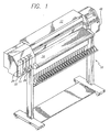
- Figure 1 is a perspective view of a large format printer in which the present invention is useful.
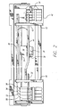
- Figure 2 is a top plan view of the printer with its cover removed to show the automatic priming pump and service station at the right end of the path of travel of the printhead carriage.
- Figure 3 is a front elevation view of the service station and priming pump.
- Figure 4 is a right side elevation view of the service station and priming pump.
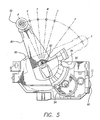
- Figure 5 is a cross-sectional elevation view taken at line 5-5 in Fig. 3, of the mechanism for moving the pump to selected positions to prime selected printheads.
- Figure 6 is a cross-sectional elevation view through the pump.
- Figure 7 is a right side elevation view of the printhead carriage with cover in the closed position.
- Figure 8 is a front elevation view of the carriage showing the printhead cover in the raised position.
- Figure 9 is a top plan view of the carriage with printheads installed in two stalls and the cover in raised position.
- Figure 10 is a plan view of the carriage cover partly broken away showing air passageways therein.
- Figure 11 is a graph plotting air pressure profiles delivered by the pump.
- Figure 12 is a graph of a velocity servo soft bump algorithm implementation.
- Figure 13 is a graph of a velocity servo hard bump algorithm implementation.
- Fig. 1 shows a
large format printer 10 of the type which includes a transversely movable printhead carriage enclosed by acover 12 which extends over a generally horizontally extendingplaten 14 over which printed media is discharged into a catcher basket. At the left side of the platen are fourremovable ink reservoirs - In the plan view of Fig. 2 in which the
carriage cover 12 has been removed, it is seen that theprinthead carriage 30 is mounted on a pair of transversely extending slider rods orguides guide support bridges rear tube guides printhead carriage 30 has a pivotal printhead hold downcover 36 fastened by alatch 38 at the front side of the printer which securely holds four inkjet printheads, two of which is shown in Fig. 9 in place in stalls C, M, Y, K on the carriage. Thefront tube guide 44 is angled near theleft bridge support 40 to provide clearance for opening theprinthead cover 36 when the carriage is slid to a position proximate the left side of theplaten 14 so that the printhead hold downcover 36 can be easily opened for changing the printheads. - A flexible ink delivery tube system conveys ink from the four
separate ink reservoirs flexible ink tubes front tube guides carriage 30. The ink tube system may be a replaceable system. - At the right side of the printer is a
printhead service station 48 at which theprinthead carriage 30 may be parked for cleaning and priming the printheads. Theprinthead service station 48 is comprised of a plastic frame mounted on the printer adjacent the right end of the transversely extending path of travel of theprinthead carriage 30. The printhead carriage 30 (Figs. 8 and 9) includes four stalls C, M, Y, K which respectively receive four separate printheads containing colored ink such as cyan, magenta, yellow and black. Theservice station 48 also includes four separate servicing stalls C, M, Y, K which may be provided on a drawer which is moveable forwardly and rearwardly of the printer. The servicing stalls each include a spittoon to capture ink discharged by the printheads during priming. The moveable drawer construction of the servicing station forms no part of the present invention. - A
printhead servicing pump 50 is mounted on the upper end of apump positioning arm 80. Agear enclosure frame 60 is affixed to the right sidewall of the frame of theservice station 48 and is spaced therefrom to provide a pocket containing a speed reduction gear mechanism which positions thearm 80 and thus thepump 50 with respect to theprinthead carriage 30. Thepositioning arm 80 is mounted for movement on apivot axis 82 extending between the right sidewall of the service station frame and thegear enclosure frame 60. An arm positioningelectric step motor 90 rotates a drive gear 92 thereon which is engaged with the teeth of a large drivengear 94 connected on a common shaft to a small drivengear 96 having teeth which mesh with an arcuatearm positioning gear 98 formed on thepump positioning arm 80 to move the arm through an angle of slightly less than 90°. Movement of thearm 80 positions the pump at various locations along an arc centered on thepivot axis 82 of the arm to align apump outlet 52 with the inlet end of one of fourair conduits printhead holddown cover 36 on theprinthead carriage 30. - The four air conduits each 100, 102, 104, 106 are each sized to have a substantially equal volume and extend from the inlet ends at the side of the hold down
cover 36 internally of the cover and terminate in downwardly directed (when the cover is closed)fluid outlets compliant seal printhead holddown cover 36 are spring loadedprinthead positioners finger latch 38 andretainer 39. - The
air pump 50, which may be removably affixed to the upper end of thepositioning arm 80 or permanently attached thereto as desired, comprises an open endedcylinder 51 in which anelongated piston 52 having a pair of spacedpiston alignment discs piston 52 is biased outwardly of the cylinder by acompression spring 55 which is seated at one end against aspring seat 56 in the pump cylinder and which is seated at its other end against acollar 57 surrounding the inner end of ahollow piston stem 58 having an elongatedaxial passageway 59 therethrough. Acompliant seal 61 is seated against the innerpiston alignment disc 54 and slideably engages the inner wall of the cylinder to provide an air seal therebetween. The walls of theseal 61 engage thecylinder 51 at an angle so that theseal 61 unidirectionally holds a positive pressure within theair chamber 68 when thepiston 52 moves to the right, but does not hold a vacuum whenpiston 52 moves to the left. The cylinder is closed by acover 63 attached to the outer wall of the cylinder by one ormore fasteners 65, the construction of which is not relevant to the present invention. Alternatively, the cover may be threadedly affixed to the cylinder. Thepiston 52 has an enlargedcollar 67 at its outer end on which acompliant gasket 69 is affixed for engaging the side wall of theprinthead holddown cover 36 and providing an air seal between theoutlet 52 of the piston and the side wall of theprinthead holddown cover 36 during positioning of the carriage against the piston at the service station. - Servicing of the printheads on the printhead carriage is accomplished in part by positioning the
pump 50 for alignment with theair passageway carriage 30 into theservice station 48 with the pump so positioned causes the carriage to engage thecompliant gasket 69 at the outlet of the pump with continued movement of the carriage moving thepump piston 52 to the right into the cylinder to discharge air from theair chamber 68 in the cylinder through thecentral passageway 59 in the piston to thus provide a source of positive air pressure to the printhead which causes ink to be forced through the printhead orifices at the bottom of the printhead into the appropriate spittoon in theservice station 48. The nozzles of the printheads C, M, Y, K may thus be primed with ink flow caused by a positive air pressure supplied by thepump 50. It will be appreciated by persons skilled in the art that the air pressure supplied by the pump need not contact the ink in the printheads and in fact should not do so to avoid introducing air which must be warehoused in the pen body. Accordingly, a printhead configuration in which ink in the printhead is contained in a chamber having a volume which can be reduced by application of air pressure to another chamber in the printhead is preferred. Travel of the printhead carriage away from thepump 50 as it leaves theservice station 48 extracts the air which has been previously forced into the printhead cover. If some of the air introduced under pressure to the printhead has escaped during the process, the pump may apply an undesired amount of vacuum to the printhead. The pump design allows the pressure to be clipped at a small negative pressure of approximately -5.0 inches of water to avoid creating a vacuum before damage is done to the printhead. The seal between the pump outlet and the passageway in the printhead holddown cover is broken after the pump piston has travelled under the bias of thespring 55 to the end of its stroke. Thus any backpressure within the printhead necessary for its correct functioning should remain unaffected by the priming operation. - The
pump 50 is arcuately postionable as best seen in Fig. 5 anywhere between arest position 0 and a reference position R which are defined bystops gear housing 52 which are engaged by the sides of thepositioning arm 80. Positions of the arm for delivery of air by the pump to the cyan, magenta, yellow and blackink printhead conduits - The
stepper motor 90 preferably steps the gear 92 at 3.75 °/half-step and the gear train preferably provides a 30:1 reduction between thestepper motor 90 and thegear 98 on thepump positioning arm 80. - The hard stops 84, 86 which define the limits of travel of the pump positioning arm are preferably placed at 84°from one another. For each printhead servicing cycle, the
pump 50 is moved from the parking orrest position 0 in which thearm 80 engages the parkinghard stop 84 to the reference position R in which the positioning arm engages thereference stop 86. Thereference stop 86 is positioned closer than the parking or rest stop 84 to the functional angular positions K, Y, M, C in which thepump 50 engages the cyan, magenta, yellow andblack printhead conduits rest position 0 to the reference position R, the arm is then moved in a reverse (clockwise as seen in Fig. 3) direction to the preliminary position P. Thestepper motor 90 then moves thepump positioning arm 80 in the original direction (counterclockwise in Fig. 3) to position thepump 50 in alignment with the desired functional location C, M, Y or K for connection to therelated conduit hard stop 86 is used to complete the accurate positioning of thepump 50 in the selected functional position. - The hard stops 84, 86 are integrally formed with the
pump positioner housing 52. This design sacrifices a small amount of positional accuracy in the nominal position of thepump 50 but decouples the hard stop function from the vertical adjustment of thepositioner housing 52. An over-stepping algorithm is used to ensure that thepump positioning arm 80 has contacted the referencehard stop 86. The over-stepping algorithm includes margin for both backlash and possible lost steps. - All functional angles are placed at even multiples of the nominal angular resolution. This is done to ensure that there are no pump positioning errors because an odd step total for a half-stepping algorithm is, by definition, less stable than an even step total.
- The inlets on the printhead holddown cover to the
conduits axis 82 of rotation of thepump positioning arm 80 and are located at the same radius as the outlet of thepump 50. Theaxis 82 of rotation of thepositioning arm 80 is placed at a maximum reasonably feasible radius from the inlets to theconduits holddown cover 36. - The radial margin around each air inlet is preferably about 2.5 mm to the inner diameter of the pump discharge gasket and 3.5 mm to the outside diameter. In the case that the vertical and horizontal alignment error of the axis of
rotation 82 of thepositioning arm 80 is 0, this translates to a stepping error of about 16 half-steps before the interface fails. - The stroke length or axial displacement of the
pump 50 may be easily selected or adjusted to discharge a controlled volume of air to each of the printheads on the carriage. Design control of the length and cross-sectional area of each of theair passageways - The pressure profile delivered by the pump is shown in Fig. 11 and is dependent upon the volume of the
air passageways air chamber 69 in the pump itself and the rest position of the printhead carriage prior to priming. The curves shown in Fig. 11 are based upon an air passageway volume of 1.8 cc and a resting pump chamber volume of 3.2 cc. Three curves are shown. The 3.5 mm COMP curve shows the pressure profile at 3.5 mm axial displacement of the pump while the 7.0 mm COMP curve shows the pressure profile at 7.0 mm axial displacement of the pump. The third curve demonstrates the curve form when an air leak in the system is present. In this case, the priming pressure delivered to the printheads is slightly diminished but is still adequate to perform the priming function. - The precise location on the printer of the position of the compliant gasket at the pump outlet is determined by the use of a novel velocity servo bumping algorithm. The algorithm has general application to any two relatively moveable components but is more conveniently described in the context of an inkjet printer with reference to movement of the carriage 30 (a first component) with respect to the pump outlet 52 (a second component) to bump the components together preferably through a number of bumping cycles during which the current drawn by an electric motor used to move the carriage to cause the relative movement between the carriage and pump outlet is measured to establish a pulse width modification (PWM) threshold which is exceeded during the bumping. The deflection of one of the components (the pump outlet) has been characterized when the load power exceeds the threshold value.
- Most bumping strategies require that the two contacting components have a minimum rigidity to function correctly. They typically assume that once the parts contact there will be no deformation or at least that the resulting deformation will be less than the precision required by the system. These algorithms, therefore, cannot be applied to systems having flexible components such as the
compliant gasket 69 at thepump outlet 52. Figure 13 shows a plot of carriage drive motor load pulse width modification (PWM) against interruptions in milliseconds for printhead carriage measurements for a hard bump environment. - To recognize the contact of a flexible component, the algorithm must react to single impulses in the PWM profile. This is to say that the servo algorithm must respond if the threshold is exceeded for a single processor interruption (1/1000 sec.). Also, the servo parameters must have a very undamped response to velocity error. The algorithm depends on the PWM instability at the point of contact to recognize the flexible component. Because the impact can be somewhat unstable and because there is additional noise in the system due to other sources, several bumping samples must be taken to insure data consistency. This data must pass the following sanity checks to be considered valid:
- 1. The average reading must not exceed a maximum variation from the nominal value (taken as 4σ of the distribution across many previous printers);
- 2. The 3σ value of the measurement distribution must not exceed a critical value for mechanism function (reading Cp); and
- 3. No single reading can vary from each machine's own distribution average by more than a critical value (erroneous data point).
- Because of the delay of the servo and the compressibility of the flexible components, an offset should be calculated when determining the bump position. As seen in the PWM evolution shown in Fig. 12 where the horizontal axis indicates interruptions in milliseconds, time B indicates when the PWM threshold (-28 as shown) was exceeded and time A indicates the point at which the true first contact occurred. The positional offset due to these effects has been characterized and shown to be repeatable. This occurs particularly in the case in which two flexible components are assembled in series (the gasket and the spring) with one of the two having a much higher stiffness and particularly preload.
- Fig. 12 also demonstrates the transient noise which occurs due to both inertial and friction/stiction effects while accelerating the carriage and approaching the pump. To reduce the risk that the PWM threshold will be exceeded during this phase, carriage movement is started sufficiently far from the nominal position to ensure that discarding the first half of the PWM profile will both eliminate this noise and ensure the flexible component (the pump) is not touched during the initial movement.
- The carriage is repeatedly positioned to deflect the pump outlet and during the bumping procedure. The currently preferred algorithm includes the following:
- 1. Number of bumping cycles: 12.
- 2. Offset due to connect gasket compression: 6 encoder units (0.25mm).
- 3. Maximum variation of average reading from nominal: 24 encoder units (1.0mm).
- 4. Maximum 3σ value: 12 encoder units.
- 5. Maximum single point deviation from average: 6 encoder units.
- It has been found that the position of the pump outlet can vary by up to 1.0 mm during construction of a printer. Use of the above positioning algorithm reduces the error between actual pump outlet position and optimum pump outlet position to a maximum of 0.25 of this amount.
- It will be appreciated by those skilled in the art that, while the specific embodiment of the present invention described utilizes a carriage actuated pump to deliver air under pressure to a printhead, the invention also extends to the use of a carriage actuated pump to generate a vacuum within a printhead and to deliver a liquid, such as ink, to a printhead.
- Persons skilled in the art will understand that the above disclosure of the preferred embodiment of the invention may be modified and that the scope of the invention is defined in its broadest sense only by the following claims.
Claims (19)
- A method of actuating a fluid pump (50) in a printer (10) to exchange fluid with an ink jet printhead without removing the printhead from a printhead carriage (30) comprising the steps ofa) providing a printhead carriage (30) having at least one fluid conduit (100,102,104,106) which conveys fluid to the printhead;b) positioning a printhead on said carriage (30), said printhead having a fluid port in fluid communication with said conduit (100,102,104,106);c) moving said printhead carriage (30) to bring said conduit (100, 102, 104, 106) into fluid transferring engagement with a fluid port of the fluid pump (50); and characterised by:d) further moving said printhead carriage (30) so as to actuate said fluid pump (50) and to discharge a predetermined amount of fluid at a predetermined pressure through said conduit (100, 102, 104, 106) with said printhead to thus provide a source of positive fluid pressure to the printhead.
- The method of claim 1, characterized by the step of actuating a pump (50) plunger by contact of said plunger with said carriage as said carriage (30) moves to a printhead service station (48).
- The method of claim 2, characterized by the step of providing multiple printheads on said carriage (30) and multiple conduits (100, 102, 104, 106) on said carriage and automatically delivering predetermined amounts of servicing fluid to selected ones of said conduits while said carriage is positioned at said service station (48).
- The method of claim 3, further characterized by the steps of:a) first moving said pump (50) in a first direction from a rest position through an are to a reference position;b) then moving said pump (50) in a second direction through an arc to a preliminary position;c) then moving said pump (50) in said first direction through an arc from said preliminary position to a desired position wherein said pump is positioned in the desired position with respect to said conduits (100,102,104,106); andd) returning said pump (50) to said rest position by moving said pump in said second direction from said desired position to said rest position.
- The method of claim 4, characterized by the further step of using an overstepping algorithm to ensure that said pump has reference position before movement of said pump (50) in said second direction.
- The method of claim 4 or 5, characterized by the further step of arcuately aligning said pump (50) positions and fluid entry ends of said conduits (100,102,104,106) at equal angular spacings from each other.
- The method of claim 6, characterized by the step of bringing said carriage (30) unto contact with said pump outlet (52) when said pump outlet is in one of said desired positions.
- The method of claim 7, characterized by the step of transferring fluid through fluid connections established between said pump outlet (52) and said fluid entry ends of said conduits (100,102,104,106) when said pump is in one of said desired positions.
- The method of any one of the preceding claims, further characterized by determining the position of said carriage (30) relative to an outlet (2) of said pump by the steps of:a) moving said carriage (30) with respect to said pump outlet (52) to bump said carriage and said outlet together;b) measuring the current drawn by a motor (90) used to move said carriage (30) during said bumping;c) establishing a threshold current which is exceeded during said bumping; andd) characterizing the deflection of one of said carriage (30) and said pump outlet (52) when said current exceeds said threshold value.
- The method of claim 9, characterized by the further step of repeatedly bumping said pump outlet (52) with said carriage (30) and establishing said threshold value based on data collected during each bumping cycle.
- The method of claim 1, characterized in that said fluid is air and further including the step of using said air to cause priming of said printhead.
- A printer which includes a moveable carriage (30) having at least one inkjet printhead thereon, said printer being characterized by: a fluid pump (50) said fluid pump (50) comprising a pump piston, said piston having a stem with a fluid discharge conduit extending through said stem to terminate at a pump outlet (52) for delivering fluid to said inkjet printhead without removing the printhead from said printhead carriage, said pump outlet (52) comprising a moveable outlet positioned on said printer proximate an end of the path of carriage travel for engagement by said carriage to actuate said pump to deliver a controlled volume of said fluid to said printhead.
- The printer of claim 12, characterized by multiple fluid delivery conduits (100,102,104,106) on said carriage (30) and a pump position actuator for moving said pump outlet (52) to a selected position to connect said pump outlet to supply fluid under pressure to a selected conduit and printhead.
- The printer of claim 13, characterized in that said actuator comprises an arm (80) pivotally mounted on said printer for movement in an arcuate path about a pivot axis (82) which extends parallel to the direction of carriage (30) movement and said pump (50) is mounted on said arm.
- The printer of claim 13 or 14, characterized in that said carriage (30) includes a pivotable printhead cover (12) and said multiple conduits (100,102,104,106) are carried by said printhead cover.
- The printer of any one of claim 12 through 15, characterized in that said pump (50) comprises: a housing defining a pump chamber (68) therein, a pump piston (52) in said chamber, a spring biasing said piston maximize the volume of said pump chamber, and a seal (111,113,115,117) at said pump outlet for engagement with a fluid delivery conduit on said printer carriage (30) in fluid communication with said printhead.
- The printer of claim 16, characterized in that said pump outlet (52) is positioned to be axially moved by engagement with a side of said carriage (30) to compress said spring to expel fluid from said stem.
- The printer of claim 16 or 17, characterized in that said seal (111,113,115,117) as of a unidirectional design.
- The printer of claim 18 characterised in that said fluid is air.
Applications Claiming Priority (2)
| Application Number | Priority Date | Filing Date | Title |
|---|---|---|---|
| US09/251,706 US6220699B1 (en) | 1999-02-17 | 1999-02-17 | Method and apparatus for actuating a pump in a printer |
| US251706 | 1999-02-17 |
Publications (3)
| Publication Number | Publication Date |
|---|---|
| EP1038680A2 EP1038680A2 (en) | 2000-09-27 |
| EP1038680A3 EP1038680A3 (en) | 2001-01-03 |
| EP1038680B1 true EP1038680B1 (en) | 2007-08-29 |
Family
ID=22953064
Family Applications (1)
| Application Number | Title | Priority Date | Filing Date |
|---|---|---|---|
| EP99110906A Expired - Lifetime EP1038680B1 (en) | 1999-02-17 | 1999-06-02 | Method and apparatus for actuating a pump in a printer |
Country Status (4)
| Country | Link |
|---|---|
| US (1) | US6220699B1 (en) |
| EP (1) | EP1038680B1 (en) |
| JP (1) | JP2000233514A (en) |
| DE (1) | DE69936976T2 (en) |
Families Citing this family (9)
| Publication number | Priority date | Publication date | Assignee | Title |
|---|---|---|---|---|
| EP1120259B1 (en) * | 2000-01-21 | 2006-11-08 | Seiko Epson Corporation | Ink-jet recording apparatus |
| US6491368B1 (en) | 2001-12-03 | 2002-12-10 | Xerox Corporation | Priming system for multicolor ink jet printers |
| JP2006150963A (en) | 2004-11-25 | 2006-06-15 | Oce Technologies Bv | Apparatus and method for controlling pressure in ink container of inkjet printer |
| US7891788B2 (en) | 2008-03-03 | 2011-02-22 | Silverbrook Research Pty Ltd | Printhead de-priming system with float valve isolation of printhead from ink reservoir |
| WO2009123636A2 (en) * | 2008-04-03 | 2009-10-08 | Hewlett-Packard Development Company, L.P. | Carriage for carrying a fluid ejector cartridge |
| US8360552B2 (en) * | 2008-04-03 | 2013-01-29 | Hewlett-Packard Development Company, L.P. | Carriage for carrying a fluid ejector cartridge |
| JP5504700B2 (en) | 2008-06-26 | 2014-05-28 | セイコーエプソン株式会社 | Liquid ejection device |
| WO2014060005A1 (en) * | 2012-10-18 | 2014-04-24 | Durst Phototechnik Digital Technology Gmbh | Two-dimensional method for inkjet printing with printhead alignment |
| CN105960334B (en) | 2014-02-13 | 2018-02-13 | 惠普发展公司,有限责任合伙企业 | The method and apparatus for irrigating print head assembly |
Family Cites Families (13)
| Publication number | Priority date | Publication date | Assignee | Title |
|---|---|---|---|---|
| US4558326A (en) * | 1982-09-07 | 1985-12-10 | Konishiroku Photo Industry Co., Ltd. | Purging system for ink jet recording apparatus |
| JPS59209878A (en) * | 1983-05-14 | 1984-11-28 | Konishiroku Photo Ind Co Ltd | Ink container for ink jet recorder |
| JPS61185451A (en) * | 1985-02-13 | 1986-08-19 | Sharp Corp | Clogging prevention apparatus of nozzle for ink jet printer |
| US4746938A (en) * | 1985-07-11 | 1988-05-24 | Matsushita Electric Industrial Co. Ltd. | Ink jet recording apparatus with head washing device |
| US4829318A (en) * | 1987-09-30 | 1989-05-09 | Dataproducts, Inc. | Head tending system for purging and cleaning an ink jet print head |
| US4853717A (en) | 1987-10-23 | 1989-08-01 | Hewlett-Packard Company | Service station for ink-jet printer |
| US5450105A (en) | 1993-04-30 | 1995-09-12 | Hewlett-Packard Company | Manual pen selection for clearing nozzles without removal from pen carriage |
| US5592201A (en) | 1994-04-28 | 1997-01-07 | Hewlett-Packard Company | Manual priming pump for inkjet printing mechanisms |
| US5872584A (en) * | 1994-10-31 | 1999-02-16 | Hewlett-Packard Company | Apparatus for providing ink to an ink-jet print head and for compensating for entrapped air |
| US5969731A (en) * | 1996-11-13 | 1999-10-19 | Hewlett-Packard Company | Print head servicing system and method employing a solid liquefiable substance |
| US5975689A (en) * | 1997-02-03 | 1999-11-02 | Hewlett-Packard Co. | Air purge apparatus for inkjet print cartridges |
| US6106109A (en) * | 1997-03-03 | 2000-08-22 | Hewlett-Packard Company | Printer apparatus for periodic automated connection of ink supply valves with multiple inkjet printheads |
| EP1275512A1 (en) * | 1997-06-04 | 2003-01-15 | Hewlett-Packard Company | Ink delivery system adapter |
-
1999
- 1999-02-17 US US09/251,706 patent/US6220699B1/en not_active Expired - Lifetime
- 1999-05-27 JP JP11148368A patent/JP2000233514A/en active Pending
- 1999-06-02 DE DE69936976T patent/DE69936976T2/en not_active Expired - Lifetime
- 1999-06-02 EP EP99110906A patent/EP1038680B1/en not_active Expired - Lifetime
Also Published As
| Publication number | Publication date |
|---|---|
| EP1038680A2 (en) | 2000-09-27 |
| EP1038680A3 (en) | 2001-01-03 |
| US6220699B1 (en) | 2001-04-24 |
| DE69936976T2 (en) | 2008-05-15 |
| JP2000233514A (en) | 2000-08-29 |
| DE69936976D1 (en) | 2007-10-11 |
Similar Documents
| Publication | Publication Date | Title |
|---|---|---|
| KR100526492B1 (en) | Apparatus and method for cleaning ink jet printer | |
| US5614929A (en) | Manual pen selection for clearing nozzles without removal from pen carriage | |
| EP1038680B1 (en) | Method and apparatus for actuating a pump in a printer | |
| US6494630B2 (en) | Datum structure for compact print cartridge | |
| US6367918B1 (en) | Unitary latching device for secure positioning of print cartridge during printing, priming and replenishment | |
| EP1029682B1 (en) | Method for servicing an inkjet printhead | |
| EP1029681B1 (en) | Printer and method for priming an inkjet printhead | |
| KR100401318B1 (en) | Capping mechanism and ink jet recording apparatus using such capping mechanism | |
| US6190007B1 (en) | Apparatus for delivering fluid to an ink jet printhead mounted on a moveable printer carriage | |
| JP2007105883A (en) | Inkjet recorder | |
| EP1080915B1 (en) | Liquid ejecting head unit | |
| JPH06336019A (en) | Ink jet recorder | |
| US11724511B2 (en) | Liquid ejection apparatus | |
| JP2000233514A5 (en) | Fluid pump operating method and printer | |
| US20080218563A1 (en) | Tube pump for fluid ejecting apparatus, fluid ejecting apparatus, and method for adjusting fluid-vacuuming capability of pump | |
| JP2007105882A (en) | Inkjet recorder and method of filling ink of inkjet head used in inkjet recorder | |
| JP2005153387A (en) | Ink supply device and inkjet recorder | |
| JP3345231B2 (en) | Pump device and ink jet head recovery device for ink jet printer | |
| JP4758571B2 (en) | Image recording device | |
| JP4266881B2 (en) | Recording device | |
| JP2675909B2 (en) | Ink jet recording device | |
| JP4211516B2 (en) | Flow path valve and liquid ejecting apparatus having the flow path valve | |
| JP2675908B2 (en) | Ink jet recording device | |
| JP2888459B2 (en) | Recording device | |
| JP2000158740A (en) | Carriage driving method and ink jet recorder |
Legal Events
| Date | Code | Title | Description |
|---|---|---|---|
| PUAI | Public reference made under article 153(3) epc to a published international application that has entered the european phase |
Free format text: ORIGINAL CODE: 0009012 |
|
| AK | Designated contracting states |
Kind code of ref document: A2 Designated state(s): DE ES GB IT |
|
| AX | Request for extension of the european patent |
Free format text: AL;LT;LV;MK;RO;SI |
|
| PUAL | Search report despatched |
Free format text: ORIGINAL CODE: 0009013 |
|
| AK | Designated contracting states |
Kind code of ref document: A3 Designated state(s): AT BE CH CY DE DK ES FI FR GB GR IE IT LI LU MC NL PT SE |
|
| AX | Request for extension of the european patent |
Free format text: AL;LT;LV;MK;RO;SI |
|
| RIC1 | Information provided on ipc code assigned before grant |
Free format text: 7B 41J 2/175 A, 7B 41J 2/165 B |
|
| 17P | Request for examination filed |
Effective date: 20010213 |
|
| RAP1 | Party data changed (applicant data changed or rights of an application transferred) |
Owner name: HEWLETT-PACKARD COMPANY, A DELAWARE CORPORATION |
|
| AKX | Designation fees paid |
Free format text: DE ES GB IT |
|
| 17Q | First examination report despatched |
Effective date: 20060629 |
|
| GRAP | Despatch of communication of intention to grant a patent |
Free format text: ORIGINAL CODE: EPIDOSNIGR1 |
|
| GRAS | Grant fee paid |
Free format text: ORIGINAL CODE: EPIDOSNIGR3 |
|
| GRAA | (expected) grant |
Free format text: ORIGINAL CODE: 0009210 |
|
| AK | Designated contracting states |
Kind code of ref document: B1 Designated state(s): DE ES GB IT |
|
| REG | Reference to a national code |
Ref country code: GB Ref legal event code: FG4D |
|
| REF | Corresponds to: |
Ref document number: 69936976 Country of ref document: DE Date of ref document: 20071011 Kind code of ref document: P |
|
| PG25 | Lapsed in a contracting state [announced via postgrant information from national office to epo] |
Ref country code: ES Free format text: LAPSE BECAUSE OF FAILURE TO SUBMIT A TRANSLATION OF THE DESCRIPTION OR TO PAY THE FEE WITHIN THE PRESCRIBED TIME-LIMIT Effective date: 20071210 |
|
| PLBE | No opposition filed within time limit |
Free format text: ORIGINAL CODE: 0009261 |
|
| STAA | Information on the status of an ep patent application or granted ep patent |
Free format text: STATUS: NO OPPOSITION FILED WITHIN TIME LIMIT |
|
| 26N | No opposition filed |
Effective date: 20080530 |
|
| GBPC | Gb: european patent ceased through non-payment of renewal fee |
Effective date: 20080602 |
|
| PG25 | Lapsed in a contracting state [announced via postgrant information from national office to epo] |
Ref country code: GB Free format text: LAPSE BECAUSE OF NON-PAYMENT OF DUE FEES Effective date: 20080602 |
|
| PG25 | Lapsed in a contracting state [announced via postgrant information from national office to epo] |
Ref country code: IT Free format text: LAPSE BECAUSE OF NON-PAYMENT OF DUE FEES Effective date: 20080630 |
|
| PGFP | Annual fee paid to national office [announced via postgrant information from national office to epo] |
Ref country code: DE Payment date: 20130523 Year of fee payment: 15 |
|
| REG | Reference to a national code |
Ref country code: DE Ref legal event code: R119 Ref document number: 69936976 Country of ref document: DE |
|
| REG | Reference to a national code |
Ref country code: DE Ref legal event code: R119 Ref document number: 69936976 Country of ref document: DE Effective date: 20150101 |
|
| PG25 | Lapsed in a contracting state [announced via postgrant information from national office to epo] |
Ref country code: DE Free format text: LAPSE BECAUSE OF NON-PAYMENT OF DUE FEES Effective date: 20150101 |