EP1037456A2 - Image reader and method for correcting the quantity of light of the readout light source - Google Patents
Image reader and method for correcting the quantity of light of the readout light source Download PDFInfo
- Publication number
- EP1037456A2 EP1037456A2 EP00105010A EP00105010A EP1037456A2 EP 1037456 A2 EP1037456 A2 EP 1037456A2 EP 00105010 A EP00105010 A EP 00105010A EP 00105010 A EP00105010 A EP 00105010A EP 1037456 A2 EP1037456 A2 EP 1037456A2
- Authority
- EP
- European Patent Office
- Prior art keywords
- document
- readout
- light
- read
- white board
- Prior art date
- Legal status (The legal status is an assumption and is not a legal conclusion. Google has not performed a legal analysis and makes no representation as to the accuracy of the status listed.)
- Ceased
Links
Images




Classifications
-
- H—ELECTRICITY
- H04—ELECTRIC COMMUNICATION TECHNIQUE
- H04N—PICTORIAL COMMUNICATION, e.g. TELEVISION
- H04N1/00—Scanning, transmission or reproduction of documents or the like, e.g. facsimile transmission; Details thereof
- H04N1/00002—Diagnosis, testing or measuring; Detecting, analysing or monitoring not otherwise provided for
- H04N1/00007—Diagnosis, testing or measuring; Detecting, analysing or monitoring not otherwise provided for relating to particular apparatus or devices
- H04N1/00013—Reading apparatus
-
- H—ELECTRICITY
- H04—ELECTRIC COMMUNICATION TECHNIQUE
- H04N—PICTORIAL COMMUNICATION, e.g. TELEVISION
- H04N1/00—Scanning, transmission or reproduction of documents or the like, e.g. facsimile transmission; Details thereof
- H04N1/00002—Diagnosis, testing or measuring; Detecting, analysing or monitoring not otherwise provided for
-
- H—ELECTRICITY
- H04—ELECTRIC COMMUNICATION TECHNIQUE
- H04N—PICTORIAL COMMUNICATION, e.g. TELEVISION
- H04N1/00—Scanning, transmission or reproduction of documents or the like, e.g. facsimile transmission; Details thereof
- H04N1/00002—Diagnosis, testing or measuring; Detecting, analysing or monitoring not otherwise provided for
- H04N1/00026—Methods therefor
- H04N1/00045—Methods therefor using a reference pattern designed for the purpose, e.g. a test chart
-
- H—ELECTRICITY
- H04—ELECTRIC COMMUNICATION TECHNIQUE
- H04N—PICTORIAL COMMUNICATION, e.g. TELEVISION
- H04N1/00—Scanning, transmission or reproduction of documents or the like, e.g. facsimile transmission; Details thereof
- H04N1/00002—Diagnosis, testing or measuring; Detecting, analysing or monitoring not otherwise provided for
- H04N1/00071—Diagnosis, testing or measuring; Detecting, analysing or monitoring not otherwise provided for characterised by the action taken
- H04N1/00082—Adjusting or controlling
-
- H—ELECTRICITY
- H04—ELECTRIC COMMUNICATION TECHNIQUE
- H04N—PICTORIAL COMMUNICATION, e.g. TELEVISION
- H04N1/00—Scanning, transmission or reproduction of documents or the like, e.g. facsimile transmission; Details thereof
- H04N1/40—Picture signal circuits
- H04N1/40056—Circuits for driving or energising particular reading heads or original illumination means
-
- H—ELECTRICITY
- H04—ELECTRIC COMMUNICATION TECHNIQUE
- H04N—PICTORIAL COMMUNICATION, e.g. TELEVISION
- H04N1/00—Scanning, transmission or reproduction of documents or the like, e.g. facsimile transmission; Details thereof
- H04N1/40—Picture signal circuits
- H04N1/401—Compensating positionally unequal response of the pick-up or reproducing head
-
- H—ELECTRICITY
- H04—ELECTRIC COMMUNICATION TECHNIQUE
- H04N—PICTORIAL COMMUNICATION, e.g. TELEVISION
- H04N1/00—Scanning, transmission or reproduction of documents or the like, e.g. facsimile transmission; Details thereof
- H04N1/40—Picture signal circuits
- H04N1/407—Control or modification of tonal gradation or of extreme levels, e.g. background level
- H04N1/4076—Control or modification of tonal gradation or of extreme levels, e.g. background level dependent on references outside the picture
-
- H—ELECTRICITY
- H04—ELECTRIC COMMUNICATION TECHNIQUE
- H04N—PICTORIAL COMMUNICATION, e.g. TELEVISION
- H04N1/00—Scanning, transmission or reproduction of documents or the like, e.g. facsimile transmission; Details thereof
- H04N1/04—Scanning arrangements, i.e. arrangements for the displacement of active reading or reproducing elements relative to the original or reproducing medium, or vice versa
- H04N1/0464—Scanning arrangements, i.e. arrangements for the displacement of active reading or reproducing elements relative to the original or reproducing medium, or vice versa capable of performing non-simultaneous scanning at more than one scanning station
-
- H—ELECTRICITY
- H04—ELECTRIC COMMUNICATION TECHNIQUE
- H04N—PICTORIAL COMMUNICATION, e.g. TELEVISION
- H04N1/00—Scanning, transmission or reproduction of documents or the like, e.g. facsimile transmission; Details thereof
- H04N1/04—Scanning arrangements, i.e. arrangements for the displacement of active reading or reproducing elements relative to the original or reproducing medium, or vice versa
- H04N1/10—Scanning arrangements, i.e. arrangements for the displacement of active reading or reproducing elements relative to the original or reproducing medium, or vice versa using flat picture-bearing surfaces
- H04N1/1013—Scanning arrangements, i.e. arrangements for the displacement of active reading or reproducing elements relative to the original or reproducing medium, or vice versa using flat picture-bearing surfaces with sub-scanning by translatory movement of at least a part of the main-scanning components
-
- H—ELECTRICITY
- H04—ELECTRIC COMMUNICATION TECHNIQUE
- H04N—PICTORIAL COMMUNICATION, e.g. TELEVISION
- H04N1/00—Scanning, transmission or reproduction of documents or the like, e.g. facsimile transmission; Details thereof
- H04N1/04—Scanning arrangements, i.e. arrangements for the displacement of active reading or reproducing elements relative to the original or reproducing medium, or vice versa
- H04N1/12—Scanning arrangements, i.e. arrangements for the displacement of active reading or reproducing elements relative to the original or reproducing medium, or vice versa using the sheet-feed movement or the medium-advance or the drum-rotation movement as the slow scanning component, e.g. arrangements for the main-scanning
-
- H—ELECTRICITY
- H04—ELECTRIC COMMUNICATION TECHNIQUE
- H04N—PICTORIAL COMMUNICATION, e.g. TELEVISION
- H04N2201/00—Indexing scheme relating to scanning, transmission or reproduction of documents or the like, and to details thereof
- H04N2201/04—Scanning arrangements
- H04N2201/0402—Arrangements not specific to a particular one of the scanning methods covered by groups H04N1/04 - H04N1/207
- H04N2201/044—Moving a scanning element into cooperation with a calibration element, e.g. a grey-wedge mounted on the document support, or vice versa
Definitions
- the present invention relates to an image reader in a scanner, a unit scanner, a facsimile and the like installed in an image forming apparatus such as a digital copying machine and the like.
- Shading correction is intended for correcting the difference in sensitivity between pixels of a sensor (CCD) which reads an image based on the reflected light from the original document, and for correcting nonuniformity in the quantity of light of a light source comprising a plurality of lamps.
- CCD sensor
- the difference in sensitivity between pixels of the readout sensor and nonuniformity in the quantity of light of the light source cause difference in the image density, and considerably decrease the reproducibility of the halftone image.
- a standard white board serving as a basis of correction is first read, then an image data including the difference in sensitivity between each pixel of the CCD and nonuniformity in the quantity of light of the light source is obtained as the shading data, and the correction value with respect to the image data is determined for each pixel based on this data, to thereby determine the threshold for the white/black judgement.
- a standard white board 82 is set between a moving document read section for reading an original document moved by the automatic document feeder 80 and a fixed document read section for reading a fixed document put on the original table 81, and the shading correction is performed in the document fixing mode and the document moving mode, using the standard white board 82.
- the optical system 83 In the case of the document fixing mode, the optical system 83 returns to the home position 84 of the optical system 83 every time when the optical system reads one sheet of document. Therefore, even in the case of continuous readout, white board 82 is irradiated to perform the shading correction every time each document is read, hence the threshold of the white/black judgement does not shift.
- the optical system 83 when the optical system 83 initiates read in of the first document, the optical system 83 moves from the home position 84 to the moving document readout position, hence after the reflected light of the white board 82 has been read at the home position for the first document, and the shading correction has been performed, the correction must be performed always at the same correction value.
- this problem can be solved by returning the optical system 83 to a predetermined home position 84 for each document to read the white board 82 and performing the shading correction, but such an operation not only conspicuously decreases the document read rate but also leads to a problem of precision of the document unit and complicated control.
- the data for shading correction is not re-acquired during continuous readout.
- the present invention is intended for solving the above described problems, and it is an object of the present invention to provide an image reader which can provide a high quality reproduced image by simply and accurately correcting the change in the quantity of light at the time of continuous readout in the document moving mode and improving the reproducibility of the halftone image, in an image reader which provides the document moving mode or the both document moving/document fixing modes, and to provide a method for correcting the quantity of light of the light source.
- the present invention has the following construction in order to attain the above described objects.
- a fist gist of the present invention is an image reader having a document moving mode in which an original document carried through a document passing area on an original table is read by a readout section, characterized in that:
- a second gist of the present invention is an image reader having both of a document fixing mode in which a readout section moves to read an original document put in a document putting area on an original table, and a document moving mode in which an original document carried through a document passing area on the original table is read by the readout section, characterized in that:
- a third gist of the present invention is an image reader according to the first or second gist, wherein the second standard white board is provided in the external region of both end portions in the main scanning direction in the document passing area.
- a fourth gist of the present invention is a method for correcting the quantity of light of a readout light source used in an image reader which irradiates an original document with the readout light source and reads the original document image based on the reflected light thereof, wherein
- a fifth gist of the present invention is a method for correcting the quantity of light of a readout light source used in an image reader which irradiates an original document with the readout light source and reads the original document image based on the reflected light thereof, wherein
- the control section performs shading correction based on the quantity of reflected light of the first standard white board arranged wider than the whole width of the document passing area or of the document putting area in the main scanning direction, for example, corrects the difference in sensitivity between pixels of the readout section and the nonuniformity in the quantity of light of the light source, immediately before starting read in of the moving document.
- the control section moves the readout section to a position where the moving document can be read, and read the quantity of reflected light of the second standard white board provided in a prescribed location at an end portion in the main scanning direction where the document does not pass through, every time predetermined moving documents are read.
- the control section detects the change in the quantity of irradiation light of the readout section based on the result, and corrects the quantity of irradiation light of the readout section (readout light source).
- the threshold of the white/black judgement determined by the shading correction does not shift, without reducing the read rate or without requiring complicated control, and high quality of reproduced document can be obtained.
- the third gist by arranging the second standard white board at both ends rather than at one end portion in the main scanning direction, more accurate correction of the quantity of light can be performed.
- the change in the quantity of light of the readout light source with lapse of time can be detected by providing the standard white board in a prescribed location in the external region of the end portion by utilizing the external region of the end portion in the main scanning direction in the area where the moving document does not pass through, and by reading the reflected light from this standard white board together with the reflected light from the moving document.
- the quantity of light of the readout light source it becomes possible to correct the quantity of light of the readout light source to the predetermined quantity of light based on the change in the quantity of light.
- the fifth gist in the document moving mode, for example, shading correction of nonuniformity in the quantity of light, difference in sensitivity of the pixel portion to be read is performed based on the reflected light of the first standard white board immediately before initiating readout of the document.
- the light source moves to the read position where the moving document is read, and even if the moving documents are continuously read to cause a change in the quantity of light due to the temperature increase of the light source, the change in the quantity of light of the readout light source can be detected and the change thereof with lapse of time can be corrected by reading the reflected light which is irradiated by using the light source and reflected from the second standard white board provided in the region where the document does not pass through, for example, in the external region of the end portion in the main scanning direction of the passing document, every time predetermined documents are read.
- the change in the quantity of light of the light source can be corrected, while performing continuous read of documents, and the quantity of light of the document can be maintained in the quantity of light corrected by using the first standard white board.
- the threshold of the white/black judgement determined by the shading correction by using the first standard white board can be maintained, without interrupting continuous read for performing the shading correction, reducing the read rate or requiring complicated control, and high quality of reproduced document can be obtained.
- an image forming apparatus which is one example of the image reader according to the present invention has an original table 2 comprising a transparent glass or the like on the upper face of the main body 1. Under the original table 2, a scanner section 3 which is an optical device is arranged.
- the scanning method of the optical device in this embodiment, a scanning method using an image sensor (for example, CCD (Charge Coupled Device), PDA (Photo Diode Array) and the like) using a light source consisting of a plurality of lamp array will be described.
- an image sensor for example, CCD (Charge Coupled Device), PDA (Photo Diode Array) and the like
- the shape of the light source for example, fluorescent light lamp, halogen lamp, flash lamp and the like as a linear light source
- any shape of the light source and any scanning method may be used so far as the quantity of irradiation light is changed with lapse of time as the moving documents are continuously read.
- the scanner section 3 in this embodiment comprises a light source 3a for irradiating light to a document put on the original table 2, a plurality of reflection mirrors 3d for guiding the reflected light from the document to a photoelectric conversion element (CCD) 3c arranged in the direction of light transmission (toward right in FIG. 2) through an imaging lens 3b in the scanner section 3, as shown in a chain line in the drawing, the aforesaid imaging lens 3b arranged in the optical path and the aforesaid CCD 3c.
- CCD photoelectric conversion element
- the image data of the document read by the CCD 3c is subjected to image processing in an image processing section described later, and sent to a laser scanning unit (hereinafter referred to as LSU) 4 in an image forming section 10. and the LSU 4 irradiates laser beam to the surface of a photosensitive member 5 to form an electrostatic latent image on the surface of the photosensitive member 5.
- LSU laser scanning unit
- the photosensitive member 5 is in a drum shape rotated and driven in the direction of an arrow.
- a development apparatus 6 for developing the electrostatic latent image on the surface of the photosensitive member exposed by the laser into a visual image by the toner
- a transfer charger 7 for transferring the toner image on the photosensitive member 5 onto a paper
- a cleaning device 8 for removing the residual toner on the surface of the photosensitive member 5
- a main charger 9 for charging the photosensitive member to the predetermined electric potential
- LSU 4 for irradiating laser beam toward the laser irradiation point on the photosensitive member 5.
- the transfer paper is stored in a paper cassette 11a in a paper feed section 11.
- a semicircular roller 12 for feeding papers is provided on the upper part of the tip on the feeding side of the paper cassette 11a and the transfer paper P pressed by the semicircular roller 12 is fed with the rotation of the semicircular roller 12.
- the image forming section 10 there are arranged, toward the downstream side in the carrying direction of the transfer paper P (for convenience sake, feeding side of the transfer paper P (cassette side) is designated as the upstream side and the paper ejection side is designated as the downstream side), a resist pre-detection switch (not shown) for detecting the passage of the transfer paper P, a resist roller 13 for performing the position adjustment of the toner image on the photosensitive member 5 and the transfer paper based on the signal from the resist pre-detection switch, a transfer charger 7 for transferring the toner image on the photosensitive member onto the transfer paper P, an upper fixing roller 14 and a lower fixing roller 15 for fixing the toner image on the transfer paper by means of heat, a fixed paper detection switch SW1 for detecting that the transfer paper passes the fixing
- a manual feed tray 17 is provided on the back side of the body 1, and depending upon the user's request, after the transfer paper has been inserted from the manual feed tray 17 to the aforesaid resist roller 13, the printing process is performed by means of the rotation of the resist roller 13 for performing the position adjustment of the toner image on the photosensitive member 5 and the transfer paper.
- the printed transfer paper is ejected to the space adjacent to the image forming section 10, and between the upper part of the paper cassette 11 and the lower part of the scanner section 3.
- the size of the image taken in the scanner section 3 is at maximum A3 or B4, and the transfer paper is at maximum A4 size.
- the size taken in the scanner section 3 is reduced and copied.
- the image forming section 10 and the paper feed section (cassette section) 11 the one which requires the biggest area as the machine structure is the scanner section 3. Since it is necessary to take a document in a big size, it requires inevitably a big area.
- the image forming apparatus in FIG. 2 has such a construction.
- the second standard white boards B and C are provided in positions which are not used for actual document read, at the end portion in the main scanning direction (MS) of the position P2 for reading the moving document (FIG. 4) in the document moving mode.
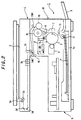
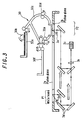
- FIG. 3 is a sectional view of the scanner section 3, and FIG. 4 is a top view of the scanner section 3.
- the scanner section 3 is provided with a document fixing-type platen glass 2a on which the document is put in the document fixing mode, and a document moving-type platen glass 2b for reading the moving document carried by the document automatic feeder 30 arranged on the upper part of the body 1 in the document moving mode.
- a belt-form first standard white board A whose whole length Y is the length extended from the width of the platen glass 2a in the main scanning direction towards both end sides by a predetermined width is arranged.
- the position where the first standard white board A is arranged is referred to as a "home position P1".
- the document putting (passing) area shown by a symbol X in FIG. 4 (hereinafter may be referred to as "document occupancy area”) is the maximum size of the document which can be read by the scanner section 3.
- the size of the platen glasses 2a and 2b in the main scanning direction of the document fixing method and the document moving method is formed larger than the document occupancy area X, and the size of the light source 3a consisting of a plurality of lamp arrays in the longitudinal direction (the main scanning direction) is also formed larger than the document occupancy area X.
- the document readout area Y where the CCD 3c can read the reflected light irradiated from the light source 3a in the document moving method is also formed longer than the document occupancy area X in the main scanning direction. Therefore, the readable area of the CCD 3c and the area between the both ends of the first standard white board A and the second standard white boards B, C are the same, hence read in of the first standard white board A and the second standard white boards B, C becomes possible.
- FIG. 5A shows the light distribution characteristic of the light source lamp at the time of read in in the main scanning direction, and shows that the peak quantity of light is after and before a predetermined time (distance) at the time of start and end of irradiation of the lamp, and the quantity of light becomes stable between the peak period.
- the light source 3a for reading the document is so set that the area of a symbol X 2 in FIG. 5A, that is, an area where the quantity of light of the light source 3a is uniform becomes the document occupancy area X used for the actual read of the document.
- a symbol Y 2 shows an irradiation period of the lamp between both ends of the first standard white board A and the second standard white boards B and C
- a symbol B 2 shows the irradiation period of the second standard white board B
- a symbol C 2 shows the irradiation period of the second standard white board C, respectively.
- FIG. 6 is a block diagram of a control system of the above described image forming apparatus 1.
- the control section 40 comprising CPU (Central Processing Unit) and the like are connected an image information processing section 41 for performing predetermined image processing to the image data and a printing processing section (image forming section) 42 for performing printing based on the image data processed in the image information processing section 41, as well as a light source unit drive control section 43, a light source lamp voltage control section 44, a shading correction section 45 and a plurality of memories 46, 47 and the like.
- CPU Central Processing Unit
- the light source unit drive control section 43 is for controlling the drive of the light source unit comprising the light source 3a and mirrors 3b of the scanner section 3, and the light source lamp voltage control section 44 is for controlling the applied voltage which determines the quantity of light of the light source 3a.
- the shading correction section 45 controls the light source unit drive control section 43 via the control section 40 to perform the above described shading correction.
- a document is put on the document feed tray 30a in the document automatic feeder 30 shown in FIG. 3, and when the start button is pushed, the document is fed from the topmost layer by a pickup roller 30b, and carried through a carrier path 30c to the moving document read section by a resist roller 30d at a timing synchronous to the read timing.
- the read document is stored in a document ejection tray 30f by means of a carrier roller 30e in the carrier path 30c, and read of the next document is performed in the similar manner.
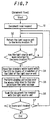
- the CCD 3c performs the shading correction for correcting the difference in sensitivity for each pixel to be read by the read sensor (CCD 3c) and the nonuniformity in the quantity of light of the light source 3a, to thereby determine the threshold of the white/black judgement at the time of reading the document for each pixel (S15).
- the data such as applied voltage to the light source 3a after the shading correction between the portions B 2 and C 2 shown in FIG. 5A and the like is stored in the memory 46 (see FIG. 6).
- the light source 3a for reading documents has the light distribution characteristic as shown in FIG. 5A, and when documents are read continuously, since the lamp temperature increases, the quantity of light decreases as a whole as shown in FIG. 5B.
- the data of quantity of light of the second standard white boards B and C read in the step (S18) is stored in the memory 47, as well as said data and the initial data of quantity of light using the first standard white board A which is stored in the memory 46 are compared in the control section 40.
- the light source lamp voltage control section 44 is controlled in the step (S20) to thereby adjust the voltage applied to the light source 3a, and the quantity of light is corrected so that the irradiation quantity to the second standard white boards B, C and the irradiation quantity to the first standard white board A become the same (see FIG. 5).
- step (S19) If the decrease in the quantity of light is not confirmed after the correction or in the step (S19), proceed to the step (S21), and if there is the next document to be read, return to the step (S17), and perform correction so that only the quantity of light of the whole area of the lamp in the light source 3a is changed to the initial quantity of light when the shading correction was performed in the step (S14).
- the shading correction using the first standard white board A can only be performed to the first document by the light source unit located in the home position P1, the quantity of light of the light source 3a is monitored with respect to the document to be read thereafter, and when the quantity of irradiation light changes due to the change of the temperature of the light source with lapse of time, it can be corrected so as to maintain the initial quantity of light by adjusting the control voltage applied to the light source 3a.
- the threshold of the white/black judgement determined by the shading correction does not shift, without reducing the read rate or without requiring complicated control, and high quality of reproduced document can be obtained.
- correction of quantity of light is performed for every document by using the second standard white boards B and C.
- the correction timing of the quantity of light can be optionally selected, and optimum timing (number of documents) can be selected depending upon the readout quantity of continuous documents and the change in the quantity of irradiation light of the light source 3a.
- the reflected light is determined at two positions of the second standard white boards B and C for performing correction of the quantity of light more reliably, but it is a matter of course that only one of them may be used.
- the control section performs shading correction based on the quantity of reflected light of the first standard white board arranged wider than the whole width of the document passing area or of the document read area in the main scanning direction, for example, corrects the difference in sensitivity between pixels of the readout section and the nonuniformity in the quantity of light of the light source, immediately before starting read in of the moving document.
- the control section moves the readout section to a position where the moving document can be read, and read the quantity of reflected light of the second standard white board provided in a prescribed location at an end portion in the main scanning direction where the document does not pass through, every time predetermined moving documents are read, and based on the result, the control section detects the change in the quantity of irradiation light of the readout section, and corrects the quantity of irradiation light of the readout light source.
- the threshold of the white/black judgement determined by the shading correction does not shift, without reducing the read rate or without requiring complicated control, and high quality of reproduced document can be obtained.
- the third gist by arranging the second standard white board at both ends rather than at one end portion in the main scanning direction, more accurate correction of the quantity of light can be performed.
- the change in the quantity of light of the readout light source with lapse of time can be detected by providing the standard white board in a prescribed location in the external region of the end portion by utilizing the external region of the end portion in the main scanning direction in the area where the moving document does not pass through, and by reading the reflected light from this standard white board together with the reflected light from the moving document.
- the quantity of light of the readout light source it becomes possible to correct the quantity of light of the readout light source to the predetermined quantity of light based on the change in the quantity of light.
- the fifth gist in the document moving mode, for example, shading correction of nonuniformity in the quantity of light, difference in sensitivity of the pixel portion to be read is performed based on the reflected light of the first standard white board immediately before initiating readout of the document. Then, the light source moves to the read position where the moving document is read, and the moving documents are continuously read to cause a change in the quantity of light due to the temperature increase of the light source.
- the change in the quantity of light of the readout light source can be detected and the change thereof with lapse of time can be corrected by reading the reflected light which is irradiated by using the light source and reflected from the second standard white board provided in the region where the document does not pass through, for example, in the external region of the end portion in the main scanning direction of the passing document, every time predetermined documents are read.
- the change in the quantity of light of the light source can be corrected, while performing continuous read of documents, and the quantity of light of the document can be maintained in the quantity of light corrected by using the first standard white board.
- the threshold of the white/black judgement determined by the shading correction by using the first standard white board can be maintained, without interrupting continuous read for performing the shading correction, reducing the read rate or requiring complicated control, and high quality of reproduced document can be obtained.
Landscapes
- Engineering & Computer Science (AREA)
- Multimedia (AREA)
- Signal Processing (AREA)
- Health & Medical Sciences (AREA)
- Biomedical Technology (AREA)
- General Health & Medical Sciences (AREA)
- Facsimile Scanning Arrangements (AREA)
- Control Of Exposure In Printing And Copying (AREA)
- Control Or Security For Electrophotography (AREA)
- Exposure Or Original Feeding In Electrophotography (AREA)
- Optical Systems Of Projection Type Copiers (AREA)
Abstract
Description
Claims (5)
- An image reader having a document moving mode in which an original document carried through a document passing area on an original table is read by a readout section, characterized in that:a first standard white board being longer than the length of said document passing area with respect to the main scanning direction is provided outside the document passing area;a second standard white board is provided in an external region of an end portion of the document passing area with respect to the main scanning direction;a control section controls the readout section in such a way that, in the document moving mode, the readout section reads the first standard white board prior to the initiation of the document read to thereby perform the shading correction, and after the document read has been initiated, said readout section reads the moving document as well as the reflected light of the second standard white board, so as to correct the quantity of irradiation light of said readout section, based on the reflected light from said second standard white board.
- An image reader having both of a document fixing mode in which a readout section moves to read an original document put in a document putting area on an original table and a document moving mode in which the original document carried through a document passing area on the original table is read by the readout section, characterized in that:a first standard white board being longer than the length of said document putting area with respect to the main scanning direction is provided outside the document putting area;a second standard white board is provided in an external region of an end portion of the document passing area with respect to the main scanning direction;a control section controls the readout section in such a way that, in the document moving mode, the readout section reads the first standard white board prior to the initiation of the document read to thereby perform the shading correction, and after the document read has been initiated, said readout section reads the moving document as well as the reflected light of the second standard white board, so as to correct the quantity of irradiation light of said readout section, based on the reflected light from said second standard white board.
- An image reader according to claim 1 or 2, wherein said second standard white board is provided in the external region of both end portions of the document passing area with respect to the main scanning direction.
- A method for correcting the quantity of light of a readout light source used in an image reader which irradiates an original document with the readout light source and reads the original document image based on the reflected light thereof, whereinin a document moving mode in which the original document moves, the moving document image is read by using said readout light source, and the reflected light from a standard white board arranged outside a document passing area is also read; andcorrection of the quantity of irradiation light of said readout light source is performed based on the reflected light from said standard white board.
- A method for correcting the quantity of light of a readout light source used in an image reader which irradiates an original document with the readout light source and reads the original document image based on the reflected light thereof, whereinin a document moving mode in which the document moves,correction of the quantity of irradiation light of the readout light source is performed by reading a first standard white board which is longer than the length in the main scanning direction of a document passing area, prior to the initiation of the document read;upon initiation of readout of the moving document, both the document and a second standard white board arranged outside the document passing area are read, by using said readout light source; andcorrection of the quantity of irradiation light of said readout light source is performed based on the reflected light from said second standard white board.
Applications Claiming Priority (2)
| Application Number | Priority Date | Filing Date | Title |
|---|---|---|---|
| JP11068978A JP2000270172A (en) | 1999-03-15 | 1999-03-15 | Image reading apparatus and light amount correction method for reading light source thereof |
| JP6897899 | 1999-03-15 |
Publications (2)
| Publication Number | Publication Date |
|---|---|
| EP1037456A2 true EP1037456A2 (en) | 2000-09-20 |
| EP1037456A3 EP1037456A3 (en) | 2003-12-17 |
Family
ID=13389280
Family Applications (1)
| Application Number | Title | Priority Date | Filing Date |
|---|---|---|---|
| EP00105010A Ceased EP1037456A3 (en) | 1999-03-15 | 2000-03-09 | Image reader and method for correcting the quantity of light of the readout light source |
Country Status (3)
| Country | Link |
|---|---|
| US (1) | US6975435B1 (en) |
| EP (1) | EP1037456A3 (en) |
| JP (1) | JP2000270172A (en) |
Cited By (2)
| Publication number | Priority date | Publication date | Assignee | Title |
|---|---|---|---|---|
| EP1835723A3 (en) * | 2006-03-17 | 2008-10-15 | Ricoh Company, Ltd. | Image reader, image processor, and computer program product |
| FR2966939A1 (en) * | 2010-10-28 | 2012-05-04 | Morpho | Grayscale image acquisition device i.e. scanner, calibrating method, involves illuminating blank leaf using light source supplied with voltage, and calibrating controlling and processing unit based on response of image sensor |
Families Citing this family (18)
| Publication number | Priority date | Publication date | Assignee | Title |
|---|---|---|---|---|
| JP3932014B2 (en) * | 2000-11-29 | 2007-06-20 | 株式会社リコー | Image reading device |
| US7327497B2 (en) | 2002-05-14 | 2008-02-05 | Canon Kabushiki Kaisha | Image reading apparatus, control method therefor, and program |
| JP3938027B2 (en) * | 2002-12-02 | 2007-06-27 | キヤノン株式会社 | Image recording / reading apparatus and prescan method |
| JP2004310386A (en) | 2003-04-04 | 2004-11-04 | Canon Inc | Image verification device, image verification method, computer program, and computer-readable recording medium |
| KR100580171B1 (en) * | 2003-06-27 | 2006-05-15 | 삼성전자주식회사 | Image scanning method and apparatus using the same |
| JP4517961B2 (en) * | 2005-07-07 | 2010-08-04 | 富士ゼロックス株式会社 | Image reading apparatus and image reading method |
| JP2007208672A (en) * | 2006-02-02 | 2007-08-16 | Fuji Xerox Co Ltd | Original reading apparatus, image forming apparatus and original reading method |
| JP2007259129A (en) * | 2006-03-23 | 2007-10-04 | Brother Ind Ltd | Image reading device |
| JP4737257B2 (en) * | 2008-09-19 | 2011-07-27 | コニカミノルタビジネステクノロジーズ株式会社 | Image reading apparatus, image forming apparatus, and carriage positioning method |
| JP5239919B2 (en) * | 2009-02-06 | 2013-07-17 | 富士ゼロックス株式会社 | Image reading apparatus and image forming apparatus |
| JP5493409B2 (en) * | 2009-03-18 | 2014-05-14 | 富士ゼロックス株式会社 | Image reading apparatus and image forming apparatus |
| JP5594988B2 (en) * | 2009-06-30 | 2014-09-24 | キヤノン株式会社 | Recording medium imaging device and image forming apparatus |
| EP2262224B1 (en) | 2009-06-05 | 2012-08-22 | Canon Kabushiki Kaisha | Recording-medium imaging device and image forming apparatus |
| JP5367509B2 (en) * | 2009-08-27 | 2013-12-11 | 株式会社東芝 | Photodetection device and paper sheet processing apparatus provided with the photodetection device |
| JP5740920B2 (en) * | 2010-11-05 | 2015-07-01 | 富士ゼロックス株式会社 | Image reading apparatus and image forming apparatus |
| JP6179436B2 (en) | 2014-03-28 | 2017-08-16 | ブラザー工業株式会社 | Image reading device |
| JP5875645B2 (en) * | 2014-08-07 | 2016-03-02 | キヤノン株式会社 | Recording medium imaging device and image forming apparatus |
| US9986129B2 (en) * | 2016-01-25 | 2018-05-29 | Seiko Epson Corporation | Scanner and image production method for sequentially storing image correction value in plurality of storage regions |
Family Cites Families (10)
| Publication number | Priority date | Publication date | Assignee | Title |
|---|---|---|---|---|
| JPS59204054A (en) | 1983-05-06 | 1984-11-19 | Canon Inc | Copying machine |
| US5151796A (en) | 1989-03-29 | 1992-09-29 | Canon Kabushiki Kaisha | Image reading apparatus having a D/A converter with a controllable output |
| JPH0335233A (en) * | 1989-06-30 | 1991-02-15 | Toshiba Corp | Image forming device |
| US5278674A (en) * | 1990-01-25 | 1994-01-11 | Hewlett-Packard Company | Method and apparatus for providing illumination compensation in a document scanner |
| JP2967361B2 (en) * | 1990-06-06 | 1999-10-25 | キヤノン株式会社 | Document reader |
| JPH06197220A (en) * | 1992-12-24 | 1994-07-15 | Tokyo Electric Co Ltd | Image reader |
| US5514864A (en) * | 1994-03-25 | 1996-05-07 | Umax Data System Inc. | Photo electric feedback compensation controlled apparatus |
| JPH0974465A (en) * | 1995-07-04 | 1997-03-18 | Ricoh Co Ltd | Document reading device |
| JPH10200711A (en) | 1997-01-16 | 1998-07-31 | Ricoh Co Ltd | Image reading device |
| DE69828542T2 (en) * | 1997-03-27 | 2005-12-22 | Seiko Epson Corp. | Shading correction for an image scanner |
-
1999
- 1999-03-15 JP JP11068978A patent/JP2000270172A/en active Pending
-
2000
- 2000-02-23 US US09/511,548 patent/US6975435B1/en not_active Expired - Fee Related
- 2000-03-09 EP EP00105010A patent/EP1037456A3/en not_active Ceased
Cited By (3)
| Publication number | Priority date | Publication date | Assignee | Title |
|---|---|---|---|---|
| EP1835723A3 (en) * | 2006-03-17 | 2008-10-15 | Ricoh Company, Ltd. | Image reader, image processor, and computer program product |
| US8159726B2 (en) | 2006-03-17 | 2012-04-17 | Ricoh Company, Limited | Image reader, image processor, and computer program product |
| FR2966939A1 (en) * | 2010-10-28 | 2012-05-04 | Morpho | Grayscale image acquisition device i.e. scanner, calibrating method, involves illuminating blank leaf using light source supplied with voltage, and calibrating controlling and processing unit based on response of image sensor |
Also Published As
| Publication number | Publication date |
|---|---|
| EP1037456A3 (en) | 2003-12-17 |
| JP2000270172A (en) | 2000-09-29 |
| US6975435B1 (en) | 2005-12-13 |
Similar Documents
| Publication | Publication Date | Title |
|---|---|---|
| US6975435B1 (en) | Image reader and method for correcting the quantity of light source | |
| US7197275B2 (en) | Image forming apparatus and image forming method including low-noise mode at paper sheet reverse section | |
| JP2021072481A (en) | Image reading device and image forming apparatus including the same | |
| JP2000284641A (en) | Image forming device | |
| US7536125B2 (en) | Image forming apparatus capable of suppressing developer waste | |
| JP3801069B2 (en) | Digital image forming device | |
| JP2003280466A (en) | Image forming device | |
| US7457009B2 (en) | Image reading apparatus and image forming apparatus | |
| US6424365B1 (en) | Image forming apparatus and method of controlling apparatus | |
| JP2003008849A (en) | Image reading device and copier | |
| US20020106218A1 (en) | Image forming apparatus with lamp burn-out detection | |
| US20080094653A1 (en) | Image reading apparatus, image reading method and image forming apparatus | |
| JP2013065949A (en) | Image reader and image forming apparatus | |
| JP3078421B2 (en) | Digital image forming apparatus and laser scanning light correction method for digital image forming apparatus | |
| JP3255574B2 (en) | Image forming apparatus and image forming method | |
| JP2006010718A (en) | Image reading apparatus and image forming apparatus | |
| JP3934385B2 (en) | Image processing apparatus, image reading apparatus, and image forming apparatus | |
| JP4004881B2 (en) | Document reader | |
| JP2003032449A (en) | Image reading device and image forming device | |
| JPH10215349A (en) | Image reader | |
| JPS60162380A (en) | Recording device | |
| JP5739775B2 (en) | Image reading apparatus, image reading method, and program | |
| JP2007180843A (en) | Image reading apparatus and image forming apparatus | |
| JP3419588B2 (en) | Automatic image reading device | |
| JPH08114956A (en) | Automatic concentration adjustment device |
Legal Events
| Date | Code | Title | Description |
|---|---|---|---|
| PUAI | Public reference made under article 153(3) epc to a published international application that has entered the european phase |
Free format text: ORIGINAL CODE: 0009012 |
|
| AK | Designated contracting states |
Kind code of ref document: A2 Designated state(s): AT BE CH CY DE DK ES FI FR GB GR IE IT LI LU MC NL PT SE |
|
| AX | Request for extension of the european patent |
Free format text: AL;LT;LV;MK;RO;SI |
|
| PUAL | Search report despatched |
Free format text: ORIGINAL CODE: 0009013 |
|
| AK | Designated contracting states |
Kind code of ref document: A3 Designated state(s): AT BE CH CY DE DK ES FI FR GB GR IE IT LI LU MC NL PT SE |
|
| AX | Request for extension of the european patent |
Extension state: AL LT LV MK RO SI |
|
| RIC1 | Information provided on ipc code assigned before grant |
Ipc: 7H 04N 1/407 B Ipc: 7H 04N 1/04 A |
|
| 17P | Request for examination filed |
Effective date: 20040506 |
|
| 17Q | First examination report despatched |
Effective date: 20040528 |
|
| AKX | Designation fees paid |
Designated state(s): DE FR GB |
|
| APBN | Date of receipt of notice of appeal recorded |
Free format text: ORIGINAL CODE: EPIDOSNNOA2E |
|
| APBR | Date of receipt of statement of grounds of appeal recorded |
Free format text: ORIGINAL CODE: EPIDOSNNOA3E |
|
| APAF | Appeal reference modified |
Free format text: ORIGINAL CODE: EPIDOSCREFNE |
|
| APBT | Appeal procedure closed |
Free format text: ORIGINAL CODE: EPIDOSNNOA9E |
|
| STAA | Information on the status of an ep patent application or granted ep patent |
Free format text: STATUS: THE APPLICATION HAS BEEN REFUSED |
|
| 18R | Application refused |
Effective date: 20090922 |