EP1037443A2 - OFDM modulator and digital broadcasting apparatus using the same - Google Patents
OFDM modulator and digital broadcasting apparatus using the same Download PDFInfo
- Publication number
- EP1037443A2 EP1037443A2 EP00105711A EP00105711A EP1037443A2 EP 1037443 A2 EP1037443 A2 EP 1037443A2 EP 00105711 A EP00105711 A EP 00105711A EP 00105711 A EP00105711 A EP 00105711A EP 1037443 A2 EP1037443 A2 EP 1037443A2
- Authority
- EP
- European Patent Office
- Prior art keywords
- data
- phase
- output
- power amplifier
- amplitude
- Prior art date
- Legal status (The legal status is an assumption and is not a legal conclusion. Google has not performed a legal analysis and makes no representation as to the accuracy of the status listed.)
- Granted
Links
Images




Classifications
-
- H—ELECTRICITY
- H04—ELECTRIC COMMUNICATION TECHNIQUE
- H04L—TRANSMISSION OF DIGITAL INFORMATION, e.g. TELEGRAPHIC COMMUNICATION
- H04L27/00—Modulated-carrier systems
- H04L27/32—Carrier systems characterised by combinations of two or more of the types covered by groups H04L27/02, H04L27/10, H04L27/18 or H04L27/26
- H04L27/34—Amplitude- and phase-modulated carrier systems, e.g. quadrature-amplitude modulated carrier systems
- H04L27/36—Modulator circuits; Transmitter circuits
- H04L27/361—Modulation using a single or unspecified number of carriers, e.g. with separate stages of phase and amplitude modulation
-
- H—ELECTRICITY
- H04—ELECTRIC COMMUNICATION TECHNIQUE
- H04L—TRANSMISSION OF DIGITAL INFORMATION, e.g. TELEGRAPHIC COMMUNICATION
- H04L27/00—Modulated-carrier systems
- H04L27/26—Systems using multi-frequency codes
- H04L27/2601—Multicarrier modulation systems
Definitions
- the present invention relates to a digital signal transmission apparatus and more particularly to an OFDM (Orthogonal Frequency Division Multiplexing) modulator and a digital broadcasting apparatus using the same.
- OFDM Orthogonal Frequency Division Multiplexing
- the OFDM modulator includes an input terminal 1 to which an input is applied, a discrete inverse Fourier transformer (IFFT) 2, two digital-to-analog converters (D/As) 10, two low pass filters (LPFs) 11, two modulators 23, a combiner 24, an A class or an AB class linear power amplifier 25, a 0°/90° phase distributor 26, and a carrier generator 9.
- the input applied to the input terminal 1 is a digital signal encoded by, e.g., an MPEG (Moving Picture coding Experts Group) 2 standard.
- the IFFT 2 transforms the input to I data and Q data which are a real axis component and an imaginary axis component, respectively.
- the I data and Q data each are input to one of the D/As 10.
- the D/As 10 respectively convert the I data and Q data input thereto to corresponding analog signals.
- the analog signals are then subjected to quadrature modulation.
- the power amplifier 25 amplifies the resulting modulated signal.
- the amplified signal output from the power amplifier 25 is sent via an antenna 14.
- the frequency spectrum several hundreds to several thousands of carrier signals are distributed in the channel frequency band.
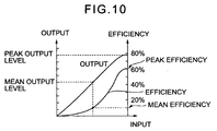
- the problem with the above conventional broadcasting apparatus is that a multicarrier signal output from the OFDM modulator is amplified by the A class or AB class linear power amplifier 25, resulting in inefficient use of power.
- the peak level and mean level of the multicarrier signal are greatly different from each other.
- the linear power amplifier 25 is used to amplify such a multicarrier signal with a minimum of distortion, the amplifier 25 has a mean output level which is about one-tenth of the peak output.
- the efficiency and therefore mean operation efficiency of the A class or AB class power amplifier 25 decreases with a decrease in output level.
- an OFDM modulator includes circuitry for converting real axis data and imaginary axis data output from a discrete inverse Fourier transformer to amplitude data and phase data on polar coordinates, and modulating the phase of a carrier wave on the basis of the phase data.
- a digital broadcasting apparatus includes the above OFDM modulator, and a power amplifier for executing amplitude modulation with the carrier wave output from the OFDM modulator with the amplitude data also output from the OFDM modulator.
- the above phase-modulated carrier wave is input to a power amplifier.
- the output of the power amplifier is controlled on the basis of the amplitude data produced by the polar coordinates conversion, thereby effecting amplitude modulation.
- SSB single sideband
- an amplitude control circuit While the amplifier is caused to perform C class operation, an amplitude control circuit constantly controls the operation to a saturation level and thereby controls an output amplitude. This allows even a nonlinear C class amplifier to produce a linear output and insures high efficiency of the C class operation.
- a digital broadcasting apparatus embodying the present invention includes an IFFT 2.
- I data 3 and Q data 4 output from the IFFT 2 are input to a polar coordinates converter 5 and converted to amplitude data 6 and phase data 7 thereby.
- FIG. 2 shows a relation between the I data 3 and Q data and the amplitude data 6 and phase data 7.
- a phase modulator (PM) 8 modulates a carrier signal output from a carrier generator 9 with the phase data 7.
- the modulated carrier signal is then converted to an analog signal by a D/A 10 and filtered by an LPF 11.
- the resulting output of the LPF 11 is input to a power amplifier 13 as an input RF (Radio Frequency) signal.
- RF Radio Frequency
- FIGS. 3A and 3B each show a particular specific configuration of the power amplifier 13.
- An FET (Field Effect Transistor) 27 and a bipolar transistor 28 shown in FIGS. 3A and 3B each are an amplifying device.
- the drain voltage or the collector voltage of the FET 27 or that of the bipolar transistor 28 is varied to vary the level of the output signal of the power amplifier 13. In this case, as shown in FIG. 4, so long as the output level of the drain voltage or that of the collector voltage is above a certain level, a constant efficiency is achievable without regard to the variation of the output signal level.
- An OFDM digital modulated wave is produced by controlling the output level of the power amplifier 12 on the basis of the previously stated amplitude data and effecting amplitude modulation.
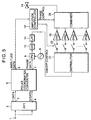
- FIG. 5 shows an alternative embodiment of the present invention.
- the I data 3 and Q data 4 output from the IFFT 2 are input to the polar coordinates converter 5 as in the previous embodiment.
- the IFFT 2 converts the I data 3 and Q data 4 to the amplitude data 6 and phase data 7. Finally, the amplitude data 6 and phase-modulated carrier wave is produced.
- the illustrative embodiment includes a power amplifying section made up of a distributor 21, N switches 22, N C class power amplifiers 15, a combiner 20, and an amplitude controller 12'.
- the distributor 21 distributes the RF signal input thereto to N outputs thereof.
- the switches 22 each ON/OFF control one of the N RF signals.
- the power amplifiers 15 each have an output which is a 2 N ratio.
- the combiner 20 combines the outputs of the power amplifiers 15.
- the amplitude controller 12' controls the combiner 20 and switches 22.
- the power amplifiers 15 each have a particular output weight.
- FIG. 6 shows specific output weights PA1, PA2, PA3 and so forth assigned to the power amplifiers 15.
- the switches 22 each ON/OFF control the RF signal input thereto on the basis of a digital signal representative of the amplitude data 6.
- the combiner 20 therefore combines only the outputs of the power amplifiers 15 whose inputs are in an ON state, thereby producing an output corresponding to the amplitude data. Consequently, as shown in FIG. 7, the level of the output signal can be varied on the basis of the combination of ON/OFF states of the power amplifiers 15. That is, amplitude modulation is effected by using the amplitude data 6 (see FIG. 6). In this case, the efficiency always has a peak value because the power amplifiers 15 in the ON state are performing C class operation.
- FIGS. 8A and 8B show a specific configuration of the combiner 20. Specifically, FIGS. 8A and 8B respectively show the basic portion and the overall configuration of the combiner 20. As shown in FIG. 8A, the basic portion includes two 3 dB couplers 16 and 18 and a phase shifter 17. As shown in FIG. 8B, the general configuration has such basic portions equal in number to the power amplifiers 15 connected in series.
- the phase shifter 17 gives the output signals of the coupler 16 a relative phase difference of 90°, i.e., delivers signals identical in amplitude, but different in phase by 90°, to the second 3 dB coupler 18. As a result, all the outputs are delivers to an output terminal 31.
- the level of the signal input to the individual basic portion of the combiner 20 depends on whether or not the output signal of the associated power amplifier 15 is present, it is possible to combine power without any loss by controlling the phase shifters 17.
- an OFDM digital broadcasting apparatus transforms an input signal to polar coordinates representative of amplitude data and phase data, modulates a carrier wave in accordance with the phase data, and varies the level of the carrier wave in accordance with the amplitude data.
- the apparatus is therefore capable of utilizing power more efficiently than the conventional OFDM digital broadcasting apparatus.
Landscapes
- Engineering & Computer Science (AREA)
- Computer Networks & Wireless Communication (AREA)
- Signal Processing (AREA)
- Amplifiers (AREA)
- Amplitude Modulation (AREA)
- Transmitters (AREA)
Abstract
Description
Claims (5)
- An OFDM (Orthogonal Frequency Division Multiplexing) modulator comprising:circuitry for converting real axis data and imaginary axis data output from a discrete inverse Fourier transformer to amplitude data and phase data on polar coordinates, and modulating a phase of a carrier wave on the basis of said phase data.
- A digital broadcasting apparatus comprising:an OFDM modulator comprising circuitry for converting real axis data and imaginary axis data output from a discrete inverse Fourier transformer to amplitude data and phase data on polar coordinates, and modulating a phase of a carrier wave on the basis of said phase data; anda power amplifier for executing amplitude modulation with the carrier wave output from said OFDM modulator with said amplitude data also output from said OFDM modulator.
- An apparatus as claimed in claim 2, wherein said power amplifier comprises an amplifying device implemented by either one of a bipolar transistor and an FET capable of performing a C class operation, a collector voltage or a drain voltage of said amplifying device being controlled on the basis of said amplitude data to thereby execute the amplitude modulation.
- An apparatus as claimed in claim 2, wherein said power amplifier comprises N power amplifying units each having an output of 2N radio and capable of performing a C class operation, said apparatus further comprising N switches for respectively ON/OFF controlling inputs to said N power amplifying units, a combiner comprising N circuits each including two 3 dB couplers and a phase shifter, and a control circuit for controlling said switches and said phase shifter in accordance with said amplitude data.
- An apparatus as claimed in claim 2, wherein said power amplifier comprises a plurality of power amplifying circuits capable of performing a C class operation and different in output from each other, said apparatus further comprising a combiner for combining outputs of said plurality of power amplifying circuits, a combination of operations of said plurality of power amplifying circuits being controlled by said amplitude data.
Applications Claiming Priority (2)
| Application Number | Priority Date | Filing Date | Title |
|---|---|---|---|
| JP7128699 | 1999-03-17 | ||
| JP07128699A JP3348676B2 (en) | 1999-03-17 | 1999-03-17 | OFDM modulator and digital broadcasting device using the same |
Publications (3)
| Publication Number | Publication Date |
|---|---|
| EP1037443A2 true EP1037443A2 (en) | 2000-09-20 |
| EP1037443A3 EP1037443A3 (en) | 2004-02-04 |
| EP1037443B1 EP1037443B1 (en) | 2005-10-26 |
Family
ID=13456317
Family Applications (1)
| Application Number | Title | Priority Date | Filing Date |
|---|---|---|---|
| EP20000105711 Expired - Lifetime EP1037443B1 (en) | 1999-03-17 | 2000-03-17 | OFDM modulator and digital broadcasting apparatus using the same |
Country Status (3)
| Country | Link |
|---|---|
| EP (1) | EP1037443B1 (en) |
| JP (1) | JP3348676B2 (en) |
| DE (1) | DE60023380T2 (en) |
Cited By (7)
| Publication number | Priority date | Publication date | Assignee | Title |
|---|---|---|---|---|
| US7116946B2 (en) | 2002-10-28 | 2006-10-03 | Matsushita Electric Industrial Co., Ltd. | Transmitter |
| US8370729B2 (en) | 2008-01-25 | 2013-02-05 | Lg Electronics Inc. | Apparatus for transmitting and receiving a signal and method of transmitting and receiving a signal |
| US8432881B2 (en) | 2007-12-12 | 2013-04-30 | Lg Electronics Inc. | Apparatus for transmitting and receiving a signal and method of transmitting and receiving a signal |
| CN101933325B (en) * | 2008-02-04 | 2013-05-29 | Lg电子株式会社 | Apparatus for transmitting and receiving a signal and method of transmitting and receiving a signal |
| US8493912B2 (en) | 2007-12-12 | 2013-07-23 | Lg Electronics Inc. | Apparatus for transmitting and receiving a signal and method of transmitting and receiving a signal |
| US9154290B2 (en) | 2007-12-12 | 2015-10-06 | Lg Electronics Inc. | Apparatus for transmitting and receiving a signal and method of transmitting and receiving a signal |
| US11238398B2 (en) | 2002-04-24 | 2022-02-01 | Ipventure, Inc. | Tracking movement of objects and notifications therefor |
Families Citing this family (3)
| Publication number | Priority date | Publication date | Assignee | Title |
|---|---|---|---|---|
| US7085327B2 (en) | 2002-10-18 | 2006-08-01 | Parker Kevin R | Phasor fragmentation circuitry and method for processing modulated signals having non-constant envelopes |
| KR100917200B1 (en) * | 2007-12-12 | 2009-09-16 | 엘지전자 주식회사 | Method of transmitting and receiving a signal and apparatus thereof |
| KR100917198B1 (en) * | 2007-12-12 | 2009-09-15 | 엘지전자 주식회사 | Method of transmitting and receiving a signal and apparatus thereof |
Family Cites Families (4)
| Publication number | Priority date | Publication date | Assignee | Title |
|---|---|---|---|---|
| US4580111A (en) * | 1981-12-24 | 1986-04-01 | Harris Corporation | Amplitude modulation using digitally selected carrier amplifiers |
| US4804931A (en) * | 1987-12-11 | 1989-02-14 | Acrodyne Industries, Inc. | Digital amplitude modulator - transmitter |
| US5469127A (en) * | 1992-08-04 | 1995-11-21 | Acrodyne Industries, Inc. | Amplification apparatus and method including modulator component |
| US6411655B1 (en) * | 1998-12-18 | 2002-06-25 | Ericsson Inc. | Systems and methods for converting a stream of complex numbers into an amplitude and phase-modulated radio power signal |
-
1999
- 1999-03-17 JP JP07128699A patent/JP3348676B2/en not_active Expired - Lifetime
-
2000
- 2000-03-17 EP EP20000105711 patent/EP1037443B1/en not_active Expired - Lifetime
- 2000-03-17 DE DE2000623380 patent/DE60023380T2/en not_active Expired - Lifetime
Cited By (13)
| Publication number | Priority date | Publication date | Assignee | Title |
|---|---|---|---|---|
| US11238398B2 (en) | 2002-04-24 | 2022-02-01 | Ipventure, Inc. | Tracking movement of objects and notifications therefor |
| US7116946B2 (en) | 2002-10-28 | 2006-10-03 | Matsushita Electric Industrial Co., Ltd. | Transmitter |
| US9154290B2 (en) | 2007-12-12 | 2015-10-06 | Lg Electronics Inc. | Apparatus for transmitting and receiving a signal and method of transmitting and receiving a signal |
| US8432881B2 (en) | 2007-12-12 | 2013-04-30 | Lg Electronics Inc. | Apparatus for transmitting and receiving a signal and method of transmitting and receiving a signal |
| US9917715B2 (en) | 2007-12-12 | 2018-03-13 | Lg Electronics Inc. | Apparatus for transmitting and receiving a signal and method of transmitting and receiving a signal |
| US8493912B2 (en) | 2007-12-12 | 2013-07-23 | Lg Electronics Inc. | Apparatus for transmitting and receiving a signal and method of transmitting and receiving a signal |
| US9590795B2 (en) | 2007-12-12 | 2017-03-07 | Lg Electronics Inc. | Apparatus for transmitting and receiving a signal and method of transmitting and receiving a signal |
| US9043687B2 (en) | 2008-01-25 | 2015-05-26 | Lg Electronics Inc. | Apparatus for transmitting and receiving a signal and method of transmitting and receiving a signal |
| US9300327B2 (en) | 2008-01-25 | 2016-03-29 | Lg Electronics Inc. | Apparatus for transmitting and receiving a signal and method of transmitting and receiving a signal |
| US8694875B2 (en) | 2008-01-25 | 2014-04-08 | Lg Electronics Inc. | Apparatus for transmitting and receiving a signal and method of transmitting and receiving a signal |
| US9847795B2 (en) | 2008-01-25 | 2017-12-19 | Lg Electronics Inc. | Apparatus for transmitting and receiving a signal and method of transmitting and receiving a signal |
| US8370729B2 (en) | 2008-01-25 | 2013-02-05 | Lg Electronics Inc. | Apparatus for transmitting and receiving a signal and method of transmitting and receiving a signal |
| CN101933325B (en) * | 2008-02-04 | 2013-05-29 | Lg电子株式会社 | Apparatus for transmitting and receiving a signal and method of transmitting and receiving a signal |
Also Published As
| Publication number | Publication date |
|---|---|
| DE60023380D1 (en) | 2005-12-01 |
| DE60023380T2 (en) | 2006-07-27 |
| JP2000269920A (en) | 2000-09-29 |
| EP1037443A3 (en) | 2004-02-04 |
| EP1037443B1 (en) | 2005-10-26 |
| JP3348676B2 (en) | 2002-11-20 |
Similar Documents
| Publication | Publication Date | Title |
|---|---|---|
| US6130910A (en) | Method and apparatus for high efficiency wideband power amplification | |
| US5705959A (en) | High efficiency low distortion amplification | |
| US9236838B2 (en) | Power amplification device | |
| KR100507592B1 (en) | Method and apparatus for efficient signal power amplification | |
| US5838210A (en) | Method and apparatus for generating a modulated signal | |
| US20020193085A1 (en) | Systems and methods for amplification of a communication signal | |
| US20080111622A1 (en) | Hybrid Doherty Amplifier System and Method | |
| US7023292B2 (en) | Polar modulation using amplitude modulated quadrature signals | |
| US5867071A (en) | High power transmitter employing a high power QAM modulator | |
| JP2002500846A (en) | Low distortion power amplifier | |
| JPH08163189A (en) | Transmission circuit | |
| CA2160592A1 (en) | Balanced modulator-transmitter | |
| US7095277B2 (en) | Method and arrangement for a power amplifier | |
| US5463355A (en) | Wideband vector modulator which combines outputs of a plurality of QPSK modulators | |
| EP1037443B1 (en) | OFDM modulator and digital broadcasting apparatus using the same | |
| US9219444B2 (en) | Broadband high efficiency amplifier system and a method of constructing high power amplitude modulated RF signal | |
| US5329259A (en) | Efficient amplitude/phase modulation amplifier | |
| US8204148B2 (en) | Space-time digital power amplifier | |
| JP2004519977A (en) | Method and apparatus for digital transmission using AM communicator | |
| JPH0918536A (en) | Modulation amplification system | |
| CN114710385B (en) | A digital-analog simulcast broadcast transmission system | |
| US12231143B2 (en) | Radio transmitter providing an analog signal with both radio frequency and baseband frequency information | |
| JPH09224064A (en) | Amplifier | |
| JP2002535868A (en) | High performance shortwave broadcasting transmitter optimized for digital broadcasting | |
| US20090042520A1 (en) | Envelope tracking RF amplifier |
Legal Events
| Date | Code | Title | Description |
|---|---|---|---|
| PUAI | Public reference made under article 153(3) epc to a published international application that has entered the european phase |
Free format text: ORIGINAL CODE: 0009012 |
|
| AK | Designated contracting states |
Kind code of ref document: A2 Designated state(s): AT BE CH CY DE DK ES FI FR GB GR IE IT LI LU MC NL PT SE |
|
| AX | Request for extension of the european patent |
Free format text: AL;LT;LV;MK;RO;SI |
|
| PUAL | Search report despatched |
Free format text: ORIGINAL CODE: 0009013 |
|
| AK | Designated contracting states |
Kind code of ref document: A3 Designated state(s): AT BE CH CY DE DK ES FI FR GB GR IE IT LI LU MC NL PT SE |
|
| AX | Request for extension of the european patent |
Extension state: AL LT LV MK RO SI |
|
| RIC1 | Information provided on ipc code assigned before grant |
Ipc: 7H 03C 5/00 B Ipc: 7H 04L 27/36 A |
|
| 17P | Request for examination filed |
Effective date: 20031230 |
|
| 17Q | First examination report despatched |
Effective date: 20040305 |
|
| AKX | Designation fees paid |
Designated state(s): DE FR GB IT |
|
| GRAP | Despatch of communication of intention to grant a patent |
Free format text: ORIGINAL CODE: EPIDOSNIGR1 |
|
| GRAS | Grant fee paid |
Free format text: ORIGINAL CODE: EPIDOSNIGR3 |
|
| GRAA | (expected) grant |
Free format text: ORIGINAL CODE: 0009210 |
|
| AK | Designated contracting states |
Kind code of ref document: B1 Designated state(s): DE FR GB IT |
|
| REG | Reference to a national code |
Ref country code: GB Ref legal event code: FG4D |
|
| REF | Corresponds to: |
Ref document number: 60023380 Country of ref document: DE Date of ref document: 20051201 Kind code of ref document: P |
|
| ET | Fr: translation filed | ||
| PLBE | No opposition filed within time limit |
Free format text: ORIGINAL CODE: 0009261 |
|
| STAA | Information on the status of an ep patent application or granted ep patent |
Free format text: STATUS: NO OPPOSITION FILED WITHIN TIME LIMIT |
|
| 26N | No opposition filed |
Effective date: 20060727 |
|
| REG | Reference to a national code |
Ref country code: FR Ref legal event code: PLFP Year of fee payment: 17 |
|
| REG | Reference to a national code |
Ref country code: FR Ref legal event code: PLFP Year of fee payment: 18 |
|
| REG | Reference to a national code |
Ref country code: FR Ref legal event code: PLFP Year of fee payment: 19 |
|
| PGFP | Annual fee paid to national office [announced via postgrant information from national office to epo] |
Ref country code: DE Payment date: 20190305 Year of fee payment: 20 Ref country code: IT Payment date: 20190326 Year of fee payment: 20 Ref country code: GB Payment date: 20190313 Year of fee payment: 20 |
|
| PGFP | Annual fee paid to national office [announced via postgrant information from national office to epo] |
Ref country code: FR Payment date: 20190213 Year of fee payment: 20 |
|
| REG | Reference to a national code |
Ref country code: DE Ref legal event code: R071 Ref document number: 60023380 Country of ref document: DE |
|
| REG | Reference to a national code |
Ref country code: GB Ref legal event code: PE20 Expiry date: 20200316 |
|
| PG25 | Lapsed in a contracting state [announced via postgrant information from national office to epo] |
Ref country code: GB Free format text: LAPSE BECAUSE OF EXPIRATION OF PROTECTION Effective date: 20200316 |