EP1037384B1 - Transversely coupled resonator type surface acoustic wave filter - Google Patents
Transversely coupled resonator type surface acoustic wave filter Download PDFInfo
- Publication number
- EP1037384B1 EP1037384B1 EP00400624A EP00400624A EP1037384B1 EP 1037384 B1 EP1037384 B1 EP 1037384B1 EP 00400624 A EP00400624 A EP 00400624A EP 00400624 A EP00400624 A EP 00400624A EP 1037384 B1 EP1037384 B1 EP 1037384B1
- Authority
- EP
- European Patent Office
- Prior art keywords
- surface acoustic
- acoustic wave
- filter
- bus bar
- exp
- Prior art date
- Legal status (The legal status is an assumption and is not a legal conclusion. Google has not performed a legal analysis and makes no representation as to the accuracy of the status listed.)
- Expired - Lifetime
Links
Images





Classifications
-
- H—ELECTRICITY
- H03—ELECTRONIC CIRCUITRY
- H03H—IMPEDANCE NETWORKS, e.g. RESONANT CIRCUITS; RESONATORS
- H03H9/00—Networks comprising electromechanical or electro-acoustic elements; Electromechanical resonators
- H03H9/25—Constructional features of resonators using surface acoustic waves
-
- H—ELECTRICITY
- H03—ELECTRONIC CIRCUITRY
- H03H—IMPEDANCE NETWORKS, e.g. RESONANT CIRCUITS; RESONATORS
- H03H9/00—Networks comprising electromechanical or electro-acoustic elements; Electromechanical resonators
- H03H9/46—Filters
- H03H9/64—Filters using surface acoustic waves
- H03H9/6423—Means for obtaining a particular transfer characteristic
- H03H9/6433—Coupled resonator filters
- H03H9/6436—Coupled resonator filters having one acoustic track only
-
- H—ELECTRICITY
- H03—ELECTRONIC CIRCUITRY
- H03H—IMPEDANCE NETWORKS, e.g. RESONANT CIRCUITS; RESONATORS
- H03H9/00—Networks comprising electromechanical or electro-acoustic elements; Electromechanical resonators
- H03H9/02—Details
- H03H9/02535—Details of surface acoustic wave devices
- H03H9/02637—Details concerning reflective or coupling arrays
- H03H9/02669—Edge reflection structures, i.e. resonating structures without metallic reflectors, e.g. Bleustein-Gulyaev-Shimizu [BGS], shear horizontal [SH], shear transverse [ST], Love waves devices
-
- H—ELECTRICITY
- H03—ELECTRONIC CIRCUITRY
- H03H—IMPEDANCE NETWORKS, e.g. RESONANT CIRCUITS; RESONATORS
- H03H9/00—Networks comprising electromechanical or electro-acoustic elements; Electromechanical resonators
- H03H9/46—Filters
- H03H9/64—Filters using surface acoustic waves
-
- H—ELECTRICITY
- H03—ELECTRONIC CIRCUITRY
- H03H—IMPEDANCE NETWORKS, e.g. RESONANT CIRCUITS; RESONATORS
- H03H9/00—Networks comprising electromechanical or electro-acoustic elements; Electromechanical resonators
- H03H9/46—Filters
- H03H9/64—Filters using surface acoustic waves
- H03H9/6423—Means for obtaining a particular transfer characteristic
- H03H9/6433—Coupled resonator filters
- H03H9/644—Coupled resonator filters having two acoustic tracks
- H03H9/6456—Coupled resonator filters having two acoustic tracks being electrically coupled
- H03H9/6459—Coupled resonator filters having two acoustic tracks being electrically coupled via one connecting electrode
- H03H9/6463—Coupled resonator filters having two acoustic tracks being electrically coupled via one connecting electrode the tracks being electrically cascaded
-
- H—ELECTRICITY
- H03—ELECTRONIC CIRCUITRY
- H03H—IMPEDANCE NETWORKS, e.g. RESONANT CIRCUITS; RESONATORS
- H03H9/00—Networks comprising electromechanical or electro-acoustic elements; Electromechanical resonators
- H03H9/02—Details
- H03H9/125—Driving means, e.g. electrodes, coils
- H03H9/145—Driving means, e.g. electrodes, coils for networks using surface acoustic waves
-
- H—ELECTRICITY
- H03—ELECTRONIC CIRCUITRY
- H03H—IMPEDANCE NETWORKS, e.g. RESONANT CIRCUITS; RESONATORS
- H03H9/00—Networks comprising electromechanical or electro-acoustic elements; Electromechanical resonators
- H03H9/46—Filters
- H03H9/64—Filters using surface acoustic waves
- H03H9/6423—Means for obtaining a particular transfer characteristic
- H03H9/6433—Coupled resonator filters
- H03H9/644—Coupled resonator filters having two acoustic tracks
- H03H9/6456—Coupled resonator filters having two acoustic tracks being electrically coupled
- H03H9/6469—Coupled resonator filters having two acoustic tracks being electrically coupled via two connecting electrodes
- H03H9/6473—Coupled resonator filters having two acoustic tracks being electrically coupled via two connecting electrodes the electrodes being electrically interconnected
-
- H—ELECTRICITY
- H03—ELECTRONIC CIRCUITRY
- H03H—IMPEDANCE NETWORKS, e.g. RESONANT CIRCUITS; RESONATORS
- H03H9/00—Networks comprising electromechanical or electro-acoustic elements; Electromechanical resonators
- H03H9/46—Filters
- H03H9/64—Filters using surface acoustic waves
- H03H9/6423—Means for obtaining a particular transfer characteristic
- H03H9/6433—Coupled resonator filters
- H03H9/6483—Ladder SAW filters
Definitions
- the present invention relates to a resonator type surface acoustic wave filter used as, for example, a bandpass filter or other type of filter. More specifically, the present invention relates to a resonator type surface acoustic wave filter including a plurality of transversely coupled surface acoustic wave resonators which generates and uses a surface acoustic wave that has a Shear Horizontal (SH) wave as its main component, such as, a Bleustein-Gulyaev-Shimizu (BGS) wave.
- SH Shear Horizontal
- BGS Bleustein-Gulyaev-Shimizu
- Various conventional surface acoustic wave filters are known bandpass filters.
- a transversely coupled surface acoustic wave filter using a Rayleigh wave as a surface acoustic wave and transversely coupled and longitudinally coupled resonator filters using a Rayleigh wave are already known bandpass filters.
- the transverse type surface acoustic wave filter is constructed such that a fixed distance separates a pair of interdigital transducers (IDTs) from each other on a surface acoustic wave substrate.
- IDTs interdigital transducers
- a plurality of surface acoustic wave resonators include a plurality of IDTs that are provided on a surface acoustic wave substrate with the plurality of surface acoustic wave resonators coupled in the transverse direction.
- reflectors are located on both sides of an area occupied by the IDTs.
- an edge reflection type surface acoustic wave filter using an SH type surface acoustic wave such as a BGS wave has been developed because the filter has the advantage of being compact.
- the filter does not have sufficient bandwidth, and although the loss can be reduced, the aperture of the electrode fingers of the IDT is about 10 ⁇ and the coupling length is about 1.5 ⁇ assuming that the wavelength of the surface acoustic wave is ⁇ . Additionally, reflectors, as described above, are required. Accordingly, the size of the filter cannot be reduced and made compact.
- preferred embodiments of the present invention provide a resonator type surface acoustic wave filter constructed so as to make use of a SH type surface acoustic wave, particularly a BGS wave, and which is miniaturized and compact size with very small insertion loss.
- a transversely coupled resonator type surface acoustic wave filter includes a surface acoustic wave substrate having opposing first and second end surfaces, first and second surface acoustic wave resonators on the surface acoustic wave substrate, and which utilizes a surface acoustic wave having an SH wave as a main component, and the first and second surface acoustic wave resonators are coupled to constitute a stage of the transversely coupled resonator filter, wherein the first and second surface acoustic wave resonators include first and second interdigital transducers, the first and second interdigital transducers defined by a first bus bar, a second bus bar and a common bus bar all arranged so as to be substantially parallel to each other and extending in a direction of transmission of the surface acoustic wave, the common bus bar is located between the first and second bus bars, and a plurality of electrode fingers are connected to the first and second bus bars at a first end of the electrode fingers and
- the coupling length x which is normalized by the wavelength ⁇ of the surface acoustic wave, satisfies the following formula: 0.71 + 1.72 ⁇ exp - E / 251 ⁇ x ⁇ 0.045 + 0.16 ⁇ exp - E / 418
- the coupling length x preferably satisfies the following formula: 0.452 + 1.953 ⁇ exp - F / 49.56 ⁇ x ⁇ 0.269 ⁇ exp - F / 32
- one bus bar of each of the first and second surface acoustic wave resonators is made a common bus bar and the width W of the common bus bar preferably satisfies the following formula: 0.32 + 0.853 ⁇ exp - E / 222 ⁇ W ⁇ 0.017 + 0.157 ⁇ exp - E / 245
- the width W of the common bus bar of the first and second surface acoustic wave resonators preferably satisfies the following formula: 0.22 + 0.84 ⁇ exp - F / 43 ⁇ W ⁇ 0.03 + 0.14 ⁇ exp - F / 21
- the filter is preferably constructed so that the gap width G between the common bus bar and the tip of a plurality of electrode fingers extending from the other bus bars meets the following formula: 1.19 + 4.51 ⁇ 10 - 4 ⁇ E - 1.34 ⁇ 10 - 6 ⁇ E 2 ⁇ G ⁇ - 0.115 + 0.29 ⁇ exp - E / 1150
- the gap width G preferably meets the following formula: 1.125 - 0.003 ⁇ F - 1.016 ⁇ 10 - 6 ⁇ F 2 ⁇ G ⁇ - 0.107 + 0.26 ⁇ exp - F / 250
- outside gap G' is also preferably made approximately equal to G.
- a resonator type surface acoustic wave filter preferably an edge reflection type surface acoustic wave filter that makes use of reflection at the end surface of a substrate is constructed.
- the resonator type surface acoustic wave filter of preferred embodiments may include one stage or a plurality of stages.
- the aperture y of the IDT is arranged to be in a certain range and ⁇ s 11 / ⁇ 0 is less than or equal to 3000, excellent resonance characteristics are achieved. That is, it is possible to provide a transversely coupled edge reflection type resonator filter that makes use of a BGS wave, although it has been heretofore been thought to be impossible.
- the filter is a resonator type surface acoustic wave filter of edge reflection type, reflectors are not required, and accordingly, it is possible to achieve a small-sized surface acoustic wave filter. Therefore, preferred embodiments of the present invention provide a surface acoustic wave filter having excellent filter characteristics while being compact.
- a communication apparatus having a duplexer includes the above described transversely coupled surface acoustic wave resonator filter.
- Fig. 1A is a plan view of a resonator type surface acoustic wave filter according to a first preferred embodiment of the present invention
- Fig. 1B is a graph illustrating the modes of a surface acoustic wave generated in the filter of Fig. 1A .
- the two coupled modes constitute a filter.
- the resonator type surface acoustic wave filter 1 is constructed preferably using a substantially rectangular surface acoustic wave substrate 2.
- the surface acoustic wave substrate 2 is preferably constructed using a piezoelectric substrate made up of piezoelectric material or by laminating thin films, such as ZnO thin films, on the substrate.
- a piezoelectric substrate made up of piezoelectric material or by laminating thin films, such as ZnO thin films, on the substrate.
- a piezoelectric single crystal such as LiTaO 3 , LiNbO 3 , or quartz, or piezoelectric ceramics such as lead titanate and zirconate type ceramics may be used.
- a thin film made of piezoelectric material such as ZnO, Ta 2 O 3 , or other similar materials is laminated on an appropriate insulating substrate such as alumina, sapphire, Si, or other similar materials.
- a piezoelectric substrate such as LiNbO 3 , quartz, or other similar materials, or a thin film such as Au or other similar materials laminated on a piezoelectric substrate can be used. Note that when a surface acoustic wave substrate is constructed by laminating a piezoelectric thin film on the substrate, the IDTs are provided on the upper or lower surface of the piezoelectric thin film.
- a first surface acoustic wave resonator is defined by the IDT 3 and a second surface acoustic wave resonator is defined by the IDT 4, and the first and second surface acoustic wave resonators are coupled laterally, that is, in a direction that is substantially perpendicular to the direction of the surface acoustic wave transmission.
- the IDTs, 3 and 4 which constitute the above-described first and second surface acoustic wave resonators, are explained in detail below.
- Two bus bars, 5 and 6, which extend in the direction of the surface acoustic wave transmission, are provided on the surface acoustic wave substrate 2.
- a common bus bar 7 is provided between the two bus bars, 5 and 6.
- the common bus bar 7 also extends in the direction of the surface acoustic wave transmission.
- a plurality of electrode fingers, 8a and 8b are connected to the bus bar 5, and the electrode fingers, 8a and 8b, extend towards the bus bar 7 in a direction that is substantially perpendicular to the direction of the surface acoustic wave transmission.
- a plurality of electrode fingers, 9a and 9b are connected to the common bus bar 7, and extend in a direction that is substantially perpendicular to the direction of the surface acoustic wave transmission.
- the electrode fingers, 9a and 9b extend toward the bus bar 5.
- the electrode fingers, 8a and 8b, and the electrode fingers, 9a and 9b, are arranged to be interdigitated.
- a plurality of electrode fingers, 10a and 10b are connected to the common bus bar 7 and extend toward the bus bar 6 such that the electrode fingers 10a and 10b extend in a direction that is substantially perpendicular to the direction of the surface acoustic wave transmission.
- a plurality of electrode fingers, 11a and 11b are connected to the bus bar 6.
- the electrode fingers, 11a and 11b extend toward the bus bar 7, and arranged so as to be interdigitated with the electrode fingers, 10a and 10b.
- the second IDT 4 is constructed.
- the tips of the electrode fingers, 8a, 8b and 11a,11b, of the first and second IDTs, 3 and 4, respectively, are separated by a coupling length x from each other in a direction that is substantially perpendicular to the direction of the surface acoustic wave transmission.
- the coupling length x means a distance in a direction that is substantially perpendicular with respect to the direction of the surface acoustic wave transmission, between the area where the electrode fingers in the one IDT 3 are interdigitally inserted and the area where the electrode fingers in the other IDT 4 are interdigitally inserted.
- the electrode finger interdigital insertion area means an area where the electrodes, 8a, 8b, 9a, and 9b, overlap with each other in the surface acoustic wave transmission direction in the IDT 3.
- the electrode finger interdigital insertion area in the IDT 4 means the same.
- an electrode finger aperture y means the length of the above-described electrode finger of the interdigital insertion area in the IDTs, 3 and 4 in a substantially perpendicular direction relative to the direction of the surface acoustic wave transmission.
- the aperture may be referred to as an IDT finger overlap length or simply as an overlap length.
- the distance between the tip of the electrode fingers, 8a and 8b, and the facing bus bar 5 is expressed by the gap length G.
- the width of the outermost electrode fingers, 8a, 9b, 10b, and 11a, in the surface acoustic wave transmission direction, out of the above electrode fingers, 8a, 8b through 11 a and 11 b, is preferably about ⁇ /8, and the width of the rest of the electrode fingers, 8b, 9a, 10a, and 11b is preferably about ⁇ /4. Further, all of the dimensions of the area between adjacent electrode fingers in the surface acoustic wave transmission direction are preferably about ⁇ /4.
- the electrode fingers, 8a and 11a are preferably arranged to extend along an edge defined at the intersection of the end surface 2a and upper surface 2c of the surface acoustic wave substrate 2.
- the electrode fingers, 9b and 10b are arranged so as to extend along an edge defined by the intersection of the end surface 2b opposed to the end surface 2a and the upper surface 2c.
- the first and second IDTs, 3 and 4 constitute a surface acoustic wave resonator of edge reflection type making use of a BGS wave, respectively.
- the IDTs, 3 and 4 can be constructed by patterning a metal film such as aluminum or other similar materials.
- the resonator type surface acoustic wave filter 1 makes use of a BGS wave. For example, by inputting an input signal between the common bus bar 7 and bus bar 5 an output signal can be taken out between the common bus bar 7 and bus bar 6. In this case, when an input signal is applied, the surface acoustic wave filter 1 generates zero-order mode and first-order mode vibrations and the combination of both makes the surface acoustic wave filter 1 function as a transversely coupled resonator type filter.
- first and second IDTs, 3 and 4 constitute an edge reflection type surface acoustic wave resonator, respectively, that is, as the resonator type surface acoustic wave filter 1 has an edge reflection type construction, no reflector is required. Accordingly, it is possible to make a compact surface acoustic wave filter.
- the first and second surface acoustic wave resonators are laterally coupled and excellent filter characteristics can be obtained.
- K 2 is an electromechanical coupling coefficient of the surface acoustic wave substrate
- the above gap width means the distance between the tip of electrode fingers and the facing bus bar. That is, when the electrode finger of 9A is taken as an example, the dimension in the direction normal to the surface acoustic wave transmission direction between the tip of the electrode finger 9a and bus bar 5 becomes a gap width of G.
- the center frequency, coupling length, and gap width were set to be 49 MHz, 0.6 ⁇ , and 0.2 ⁇ , respectively.
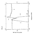
- Figs. 2 through 4 the respective frequency characteristics of these resonator type surface acoustic wave filters are shown.
- Fig. 2 shows the frequency characteristic when the electrode finger aperture length in the IDTs, 3 and 4, is 4 ⁇ .
- Fig. 3 shows the case where the aperture length is 1.5 ⁇ , and
- Fig. 4 shows the case when aperture length is 0.3 ⁇ .
- the one-dot chain line shows the expansion in the axis of frequency and amplitude of the characteristic shown by a solid line.
- Fig. 5 shows the relationship between the relative dielectric constant ⁇ s 11 / ⁇ 0 of the piezoelectric material constituting the surface acoustic wave substrate 2 and the aperture y in the IDTs, 3 and 4.
- the solid curved lines, A and B were obtained by approximating the lines to the upper and lower limits of a set of points having a good filter characteristic which were measured as in the above.
- Fig. 6 shows the relationship between the product K 2 ⁇ s 11 / ⁇ 0 of the electromechanical coupling coefficient K 2 and the relative dielectric constant ⁇ s 11 / ⁇ 0 of the piezoelectric material constituting a surface acoustic wave substrate 2 and the electrode finger aperture in the IDTs, 3 and 4.
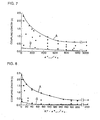
- Fig. 7 shows the relative dielectric constant ⁇ s 11 / ⁇ 0 of the piezoelectric material constituting a surface acoustic wave substrate 2 and the coupling length x.
- Fig. 8 shows the relationship between K 2 ⁇ s 11 and the coupling length x.
- Fig. 9 shows the relationship between the relative dielectric constant ⁇ s 11 / ⁇ 0 of the dielectric material constituting a surface acoustic wave substrate 2 and the width W of a common bus bar 7.
- Fig. 10 shows the relationship between K 2 ⁇ s 11 / ⁇ 0 and the width W of a common bus bar 7.
- Fig. 11 shows the relationship between the relative dielectric constant ⁇ s 11 / ⁇ 0 of the dielectric material constituting a surface acoustic wave substrate 2 and a gap width of G.
- Fig. 12 shows the relationship between K 2 ⁇ s 11 / ⁇ 0 and a gap width G.
- the same result can be obtained by constructing the filter using reflectors provided on the surface acoustic wave substrate so as to interpose the first and second IDTs, instead of edge reflection type structures.
- the IDT may be divided into a plurality of sub-IDT portions connected in series with each other.
- the present invention can be suitably applied to various electronic components, apparatuses or devices utilizing a surface acoustic wave filter in which the unique features of the present invention are successfully used.
- the present invention may be applied to a duplexer and communication apparatus including the duplexer.
- Fig. 13 is a block diagram of a communication apparatus 50 having a duplexer 40.
- the communication apparatus 50 may be a cellular phone, for example, because a cellular phone which usually requires a small hand-held body and a high efficiency is suitable to enjoy the aforementioned merits of the filter according to various preferred embodiments of the present invention.
- the communication apparatus 50 preferably includes duplexer 40, an antenna 51, a receiver 52 and a transmitter 53.
- the duplexer 40 preferably includes a SAW filter 41 and a SAW filter 42, and one end of each of the SAW filter 41 and the SAW filter 42 are connected in parallel to define a first terminal 43. The other ends of the SAW filter 41 and the SAW filter 42 are connected to a second terminal 44 and a third terminal 45, respectively.
- the SAW filter 41 and the SAW filter 42 may be any one of the SAW filters explained in the aforementioned examples.
- the antenna 51, the receiver 52 and the transmitter 53 are connected to the first terminal 43, the second terminal 44 and the third terminal 45 of the duplexer 40, respectively.
- the pass bands of the SAW filters 41 and 42 of the duplexer 40 are selected such that the signals received through the antenna 51 pass through the SAW filter 41 and are blocked by the SAW filter 42 and that the signals to be transmitted from the transmitter 53 pass through the SAW filter 42.
Landscapes
- Physics & Mathematics (AREA)
- Acoustics & Sound (AREA)
- Surface Acoustic Wave Elements And Circuit Networks Thereof (AREA)
Description
- The present invention relates to a resonator type surface acoustic wave filter used as, for example, a bandpass filter or other type of filter. More specifically, the present invention relates to a resonator type surface acoustic wave filter including a plurality of transversely coupled surface acoustic wave resonators which generates and uses a surface acoustic wave that has a Shear Horizontal (SH) wave as its main component, such as, a Bleustein-Gulyaev-Shimizu (BGS) wave.
- Various conventional surface acoustic wave filters are known bandpass filters. For example, a transversely coupled surface acoustic wave filter using a Rayleigh wave as a surface acoustic wave, and transversely coupled and longitudinally coupled resonator filters using a Rayleigh wave are already known bandpass filters.
- The transverse type surface acoustic wave filter is constructed such that a fixed distance separates a pair of interdigital transducers (IDTs) from each other on a surface acoustic wave substrate.
- Further, in the transversely coupled resonator filter using a Rayleigh wave, a plurality of surface acoustic wave resonators include a plurality of IDTs that are provided on a surface acoustic wave substrate with the plurality of surface acoustic wave resonators coupled in the transverse direction. In the transversely coupled resonator filter, reflectors are located on both sides of an area occupied by the IDTs.
- Recently, an edge reflection type surface acoustic wave filter using an SH type surface acoustic wave such as a BGS wave has been developed because the filter has the advantage of being compact.
- In a transversely coupled surface acoustic wave filter using the Rayleigh wave, because two sets of IDTs are separated by a fixed distance along the direction of the surface-wave transmission on a surface acoustic wave substrate, the size of the filter cannot be reduced and is instead much larger. Also, the insertion loss is very large.
- In a transversely coupled resonator filter using a Rayleigh wave, because the electromechanical coupling coefficient K is small, the filter does not have sufficient bandwidth, and although the loss can be reduced, the aperture of the electrode fingers of the IDT is about 10 λ and the coupling length is about 1.5 λ assuming that the wavelength of the surface acoustic wave is λ. Additionally, reflectors, as described above, are required. Accordingly, the size of the filter cannot be reduced and made compact.
- Further, in an edge reflection type surface acoustic wave resonator using a SH type surface acoustic wave, a resonator with a wide bandwidth is obtained, which is due to the relatively large electromechanical coupling coefficient K, so that no reflectors are required. Further, the edge reflection type resonator is favorable because it can be made compact. However, up until now, when a SH type surface acoustic wave was used, the construction of a filter by coupling the plurality of surface acoustic wave resonators was considered to be impossible. For instance
patent application EP-A-0854571 discloses a transversally coupled resonator type saw device without however providing important aspects on parameters like the aperture. - To overcome the problems of the related art described above, preferred embodiments of the present invention provide a resonator type surface acoustic wave filter constructed so as to make use of a SH type surface acoustic wave, particularly a BGS wave, and which is miniaturized and compact size with very small insertion loss.
- A transversely coupled resonator type surface acoustic wave filter according to the present invention includes a surface acoustic wave substrate having opposing first and second end surfaces, first and second surface acoustic wave resonators on the surface acoustic wave substrate, and which utilizes a surface acoustic wave having an SH wave as a main component, and the first and second surface acoustic wave resonators are coupled to constitute a stage of the transversely coupled resonator filter, wherein the first and second surface acoustic wave resonators include first and second interdigital transducers, the first and second interdigital transducers defined by a first bus bar, a second bus bar and a common bus bar all arranged so as to be substantially parallel to each other and extending in a direction of transmission of the surface acoustic wave, the common bus bar is located between the first and second bus bars, and a plurality of electrode fingers are connected to the first and second bus bars at a first end of the electrode fingers and extended towards the common bus bar, a plurality of electrode fingers are connected to the common bus bar at a first end of the electrode fingers and such that a first set of electrode fingers of the common bus bar are extended towards the first bus bar and a second set of electrode fingers are extended towards the second bus bar so that the first and second sets of electrode fingers of the common bus bar interdigitate with the electrode fingers of the first and second bus bars, wherein the surface acoustic wave substrate has a relative dielectric constant E along the direction of 11 of the surface acoustic wave substrate such that E = εs 11/ε0, and where E is less than or equal to 3000, wherein an aperture y of the interdigital transducer is defined as an amount of overlap between the electrode fingers of the common bus bar with the electrode fingers of the first and second bus bars normalized by the wavelength λ of the surface acoustic wave, and wherein the filter is constructed such that y satisfies the formula:

- Also, when K is an electromechanical coupling coefficient of the surface acoustic wave substrate, the filter is preferably arranged such that F = K2·εs 11/ε0, and F is less than or equal to 250 and the aperture y of the interdigital transducer further satisfies the following formula:

- Further, in a transversely coupled resonator type surface acoustic wave filter, preferably, the coupling length x, which is normalized by the wavelength λ of the surface acoustic wave, satisfies the following formula:

- Preferably, if the filter is constructed so that F = K2·εS 11/ε0 is less than or equal to 250 then the coupling length x preferably satisfies the following formula:

- Further, one bus bar of each of the first and second surface acoustic wave resonators is made a common bus bar and the width W of the common bus bar preferably satisfies the following formula:

- Also, if the filter is constructed so that K2·εs 11/ε0 is less than or equal to 250, then the width W of the common bus bar of the first and second surface acoustic wave resonators preferably satisfies the following formula:

- Further, the filter is preferably constructed so that the gap width G between the common bus bar and the tip of a plurality of electrode fingers extending from the other bus bars meets the following formula:

- Also, if the filter is constructed so that F = K2·εs 11/ε0 is less than or equal to 250, then the gap width G preferably meets the following formula:

- Moreover, the outside gap G' is also preferably made approximately equal to G.
- In a resonator type surface acoustic wave filter, preferably an edge reflection type surface acoustic wave filter that makes use of reflection at the end surface of a substrate is constructed.
- Further, the resonator type surface acoustic wave filter of preferred embodiments may include one stage or a plurality of stages.
- In the transversely coupled resonator filter, because the aperture y of the IDT is arranged to be in a certain range and εs 11/ε0 is less than or equal to 3000, excellent resonance characteristics are achieved. That is, it is possible to provide a transversely coupled edge reflection type resonator filter that makes use of a BGS wave, although it has been heretofore been thought to be impossible.
- Also, because the filter is a resonator type surface acoustic wave filter of edge reflection type, reflectors are not required, and accordingly, it is possible to achieve a small-sized surface acoustic wave filter. Therefore, preferred embodiments of the present invention provide a surface acoustic wave filter having excellent filter characteristics while being compact.
- Further, by satisfying the given ranges for the aperture, coupling length, width of the common bus bar, and gap width in accordance with εs 11/ε0 and K2. εs 11/ε0, greatly improved filter characteristics are achieved. Also, because the reflectance ratio and reflection efficiency are high compared with those in the reflector of electrode fingers, a low-loss and wideband filter can be realized.
- In another preferred embodiment of the present invention, a communication apparatus having a duplexer includes the above described transversely coupled surface acoustic wave resonator filter.
- Other features, elements and advantages of the present invention will be described in detail below with reference to preferred embodiments of the present invention and the attached drawings.
- The present invention will become more fully understood form the detailed description given herein below and the accompanying drawings which are given by way of illustration only, and thus do not limit the present invention and wherein:
-
Figs. 1A is a plan view of a resonator type surface acoustic wave filter according to a first preferred embodiment of the present invention; -
Fig. 1B is a graph illustrating the mode of a surface acoustic wave used for excitation; -
Fig. 2 shows the impedance vs. frequency characteristics of a transversely coupled resonator type surface acoustic wave filter where the aperture of the electrode fingers is 4.0 λ; -
Fig. 3 shows the impedance vs. frequency characteristics of a transversely coupled resonator type surface acoustic wave filter where the aperture of the electrode fingers is 1.5 λ; -
Fig. 4 shows the impedance vs. frequency characteristics of a transversely coupled resonator type surface acoustic wave filter where the aperture of the electrode fingers is 0.3 λ; -
Fig. 5 shows the relationship between the relative dielectric constant ε s 11 /ε 0 and the aperture length in a transversely coupled resonator type surface acoustic wave filter; -
Fig. 6 shows the relationship between K2·εs 11/ε0 and the aperture length in a transversely coupled resonator type surface acoustic wave filter; -
Fig. 7 shows the relationship between the relative dielectric constant ε s 11/ε0 and the coupling length in a transversely coupled resonator type surface acoustic wave filter; -
Fig. 8 shows the relationship between K2·εs 11/ε0 and the coupling length in a transversely coupled resonator type surface acoustic wave filter; -
Fig. 9 shows the relationship between the relative dielectric constant ε s 11/ε0 and the width of the common bus bar in a transversely coupled resonator type surface acoustic wave filter; -
Fig. 10 shows the relationship between K2·εs11/ε0 and the width of the common bus bar in a transversely coupled resonator type surface acoustic wave filter; -
Fig. 11 shows the relationship between the relative dielectric constant εs 11/ε0 and the gap width G in a transversely coupled resonator type surface acoustic wave filter; -
Fig. 12 shows the relationship between K2·εs 11/ε0 and the gap width G in a transversely coupled resonator type surface acoustic wave filter; and -
Fig. 13 is a block diagram of a duplexer and a communication apparatus according to another preferred embodiment of the present invention. -
Fig. 1A is a plan view of a resonator type surface acoustic wave filter according to a first preferred embodiment of the present invention, andFig. 1B is a graph illustrating the modes of a surface acoustic wave generated in the filter ofFig. 1A . The two coupled modes constitute a filter. - The resonator type surface
acoustic wave filter 1 is constructed preferably using a substantially rectangular surfaceacoustic wave substrate 2. - The surface
acoustic wave substrate 2 is preferably constructed using a piezoelectric substrate made up of piezoelectric material or by laminating thin films, such as ZnO thin films, on the substrate. In making the piezoelectric substrate, a piezoelectric single crystal such as LiTaO3, LiNbO3, or quartz, or piezoelectric ceramics such as lead titanate and zirconate type ceramics may be used. Further, when the surfaceacoustic wave substrate 2 is constructed by providing a thin film on the substrate, a thin film made of piezoelectric material such as ZnO, Ta2O3, or other similar materials is laminated on an appropriate insulating substrate such as alumina, sapphire, Si, or other similar materials. Alternatively, a piezoelectric substrate such as LiNbO3, quartz, or other similar materials, or a thin film such as Au or other similar materials laminated on a piezoelectric substrate can be used. Note that when a surface acoustic wave substrate is constructed by laminating a piezoelectric thin film on the substrate, the IDTs are provided on the upper or lower surface of the piezoelectric thin film. - In the resonator type surface
acoustic wave filter 1, IDTs, 3 and 4, are provided on the upper surface of the surfaceacoustic wave substrate 2. According to the present preferred embodiment, a first surface acoustic wave resonator is defined by theIDT 3 and a second surface acoustic wave resonator is defined by theIDT 4, and the first and second surface acoustic wave resonators are coupled laterally, that is, in a direction that is substantially perpendicular to the direction of the surface acoustic wave transmission. - The IDTs, 3 and 4, which constitute the above-described first and second surface acoustic wave resonators, are explained in detail below. Two bus bars, 5 and 6, which extend in the direction of the surface acoustic wave transmission, are provided on the surface
acoustic wave substrate 2. Also, acommon bus bar 7 is provided between the two bus bars, 5 and 6. Thecommon bus bar 7 also extends in the direction of the surface acoustic wave transmission. A plurality of electrode fingers, 8a and 8b, are connected to thebus bar 5, and the electrode fingers, 8a and 8b, extend towards thebus bar 7 in a direction that is substantially perpendicular to the direction of the surface acoustic wave transmission. Also, a plurality of electrode fingers, 9a and 9b are connected to thecommon bus bar 7, and extend in a direction that is substantially perpendicular to the direction of the surface acoustic wave transmission. The electrode fingers, 9a and 9b, extend toward thebus bar 5. The electrode fingers, 8a and 8b, and the electrode fingers, 9a and 9b, are arranged to be interdigitated. - Additionally, a plurality of electrode fingers, 10a and 10b are connected to the
common bus bar 7 and extend toward thebus bar 6 such that theelectrode fingers bus bar 6. The electrode fingers, 11a and 11b, extend toward thebus bar 7, and arranged so as to be interdigitated with the electrode fingers, 10a and 10b. In the portion where the electrode fingers, 10a and 10b, and electrode fingers, 11a and 11b, are provided, thesecond IDT 4 is constructed. - The tips of the electrode fingers, 8a, 8b and 11a,11b, of the first and second IDTs, 3 and 4, respectively, are separated by a coupling length x from each other in a direction that is substantially perpendicular to the direction of the surface acoustic wave transmission. Here, the coupling length x means a distance in a direction that is substantially perpendicular with respect to the direction of the surface acoustic wave transmission, between the area where the electrode fingers in the one
IDT 3 are interdigitally inserted and the area where the electrode fingers in theother IDT 4 are interdigitally inserted. - Further, the electrode finger interdigital insertion area means an area where the electrodes, 8a, 8b, 9a, and 9b, overlap with each other in the surface acoustic wave transmission direction in the
IDT 3. The electrode finger interdigital insertion area in theIDT 4 means the same. - Further, an electrode finger aperture y means the length of the above-described electrode finger of the interdigital insertion area in the IDTs, 3 and 4 in a substantially perpendicular direction relative to the direction of the surface acoustic wave transmission. The aperture may be referred to as an IDT finger overlap length or simply as an overlap length.
- In the IDTs, 3 and 4, the distance between the tip of the electrode fingers, 8a and 8b, and the facing
bus bar 5 is expressed by the gap length G. - The width of the outermost electrode fingers, 8a, 9b, 10b, and 11a, in the surface acoustic wave transmission direction, out of the above electrode fingers, 8a, 8b through 11 a and 11 b, is preferably about λ/8, and the width of the rest of the electrode fingers, 8b, 9a, 10a, and 11b is preferably about λ/4. Further, all of the dimensions of the area between adjacent electrode fingers in the surface acoustic wave transmission direction are preferably about λ/4.
- The electrode fingers, 8a and 11a, are preferably arranged to extend along an edge defined at the intersection of the
end surface 2a andupper surface 2c of the surfaceacoustic wave substrate 2. Similarly, the electrode fingers, 9b and 10b, are arranged so as to extend along an edge defined by the intersection of the end surface 2b opposed to theend surface 2a and theupper surface 2c. - That is, the first and second IDTs, 3 and 4, constitute a surface acoustic wave resonator of edge reflection type making use of a BGS wave, respectively.
- The IDTs, 3 and 4, can be constructed by patterning a metal film such as aluminum or other similar materials.
- The resonator type surface
acoustic wave filter 1 according to the present preferred embodiment makes use of a BGS wave. For example, by inputting an input signal between thecommon bus bar 7 andbus bar 5 an output signal can be taken out between thecommon bus bar 7 andbus bar 6. In this case, when an input signal is applied, the surfaceacoustic wave filter 1 generates zero-order mode and first-order mode vibrations and the combination of both makes the surfaceacoustic wave filter 1 function as a transversely coupled resonator type filter. - Further, because the first and second IDTs, 3 and 4, constitute an edge reflection type surface acoustic wave resonator, respectively, that is, as the resonator type surface
acoustic wave filter 1 has an edge reflection type construction, no reflector is required. Accordingly, it is possible to make a compact surface acoustic wave filter. - Further, in the resonator type surface
acoustic wave filter 1 of the present preferred embodiment, by choosing the most appropriate aperture, coupling length, common bus bar, and gap width in accordance with the value of the relative dielectric constant εs 11/ε0 or K2·εs 11/ε0 in the direction of 11 of the above surfaceacoustic wave substrate 2 where the distortion is constant, the first and second surface acoustic wave resonators are laterally coupled and excellent filter characteristics can be obtained. Moreover, K2 is an electromechanical coupling coefficient of the surface acoustic wave substrate, and the above gap width means the distance between the tip of electrode fingers and the facing bus bar. That is, when the electrode finger of 9A is taken as an example, the dimension in the direction normal to the surface acoustic wave transmission direction between the tip of theelectrode finger 9a andbus bar 5 becomes a gap width of G. - Hereinafter, this is explained based on the following experimental example.
- As the above transversely coupled surface acoustic
wave resonator filter 1, various surfaceacoustic wave filters 1 were produced by forming IDTs, 3 and 4, having electrode finger apertures variously changed on the surfaceacoustic wave substrate 2 of εs 11/ε0 = 470, K2·εs 11/ε0 = 25, and a piezoelectric ceramic having approximate dimensions of 2.1 mm x 1.5 mm x 0.5 mm. Moreover, in all of the filters, the center frequency, coupling length, and gap width were set to be 49 MHz, 0.6 λ, and 0.2 λ, respectively. - In
Figs. 2 through 4 , the respective frequency characteristics of these resonator type surface acoustic wave filters are shown.Fig. 2 shows the frequency characteristic when the electrode finger aperture length in the IDTs, 3 and 4, is 4 λ.Fig. 3 shows the case where the aperture length is 1.5 λ, andFig. 4 shows the case when aperture length is 0.3 λ. Moreover, inFigs. 2 through 4 , the one-dot chain line shows the expansion in the axis of frequency and amplitude of the characteristic shown by a solid line. - As is clearly seen in
Figs. 2 through 4 , in the case where the electrode finger aperture length is 1.5 X, that is, which is within the range showing a good characteristic as inFig. 5 , which is to be described later, because the transverse mode coupling is good, good frequency characteristics are obtained, but in the case of 4λ, good characteristics are not obtained. In the case where electrode finger aperture length is 0.3 λ inFig. 4 , a certain characteristic is obtained, but it is not as good as the characteristics shown inFig. 3 . This is because the condition is outside the range in which good characteristics, as shown inFig. 5 , can be obtained. - Next, using various materials as shown in the following Table 1 as a piezoelectric material constituting a surface
acoustic wave substrate 2, the condition when good filter characteristics as shown inFig. 3 can be obtained was examined. That is, by using various surfaceacoustic wave substrates 2 and changing the coupling length x, electrode finger aperture length y, width of thecommon bus bar 7, and gap width G in various ways, these optimum values were sought.Table 1 Material εs 11/ε0 K K2·εs 11/ε0 Piezoelectric ceramic A 470 0.23 25 B 800 0.47 177 C 205 0.18 6.6 D 1000 0.51 260 LiTaO 343 0.22 2.1 Piezoelectric ceramic Pb(ZrxTi(1-x))O3
A x = 0.38
B x = 0.48
C x = 0.34
D x = 0.53 - The result is shown in
Figs. 5 through 12 .Fig. 5 shows the relationship between the relative dielectric constant εs 11/ε0 of the piezoelectric material constituting the surfaceacoustic wave substrate 2 and the aperture y in the IDTs, 3 and 4. The solid curved lines, A and B, were obtained by approximating the lines to the upper and lower limits of a set of points having a good filter characteristic which were measured as in the above. When the solid line A inFig. 5 is expressed by a formula, it becomes y = 0.945 + 5.49 × exp(-E/366), and the solid line B becomes y = 2.46 × exp(-E/219), where E = εs 11/ε0. - Accordingly, from the result of
Fig. 5 , it is understood that when the electrode finger aperture y in the IDTs, 3 and 4, is in the range where the above formula (1) is met, excellent filter characteristics can be obtained. - In addition, all of the curved solid lines, A and B, in the following
Figs. 6 through 12 were obtained by approximating the lines to the portions along the upper and lower limits of the sets of the measured points corresponding to excellent filter characteristics. -
Fig. 6 shows the relationship between the product K2·εs 11/ε0 of the electromechanical coupling coefficient K2 and the relative dielectric constant εs 11/ε0 of the piezoelectric material constituting a surfaceacoustic wave substrate 2 and the electrode finger aperture in the IDTs, 3 and 4. The solid line A inFig. 6 is expressed by a formula of y = 1.40 + 4. 14 × exp(-F/46), and the solid line B is expressed by y = 0.25 + 0.97 × exp(-F/42). Therefore, fromFig. 6 , it is understood that when the electrode finger aperture y is in the range where above-mentioned formula (2) is satisfied, excellent filter characteristic can be obtained. - More, although it is stated in
U.S. Patent No. 5,708,403 that in an end surface reflection resonator using a BGS wave produced in a PZT substrate, an optimum aperture is in the range of 2.8λ to 3.1λ, it was confirmed that the optimum apertures of resonators and filters are different and they do not overlap. -
Fig. 7 shows the relative dielectric constant εs 11/ε0 of the piezoelectric material constituting a surfaceacoustic wave substrate 2 and the coupling length x. The solid line A ofFig. 7 is expressed by a formula of x = 0.71 + 1.72 × exp(-E/251), and the solid line B is expressed by x = 0.045 + 0.16 × exp(-E/418) Therefore, it is understood that when a filter is constructed so that the coupling length x satisfies above-mentioned formula (3), excellent filter characteristics can be obtained. -
Fig. 8 shows the relationship between K2·εs 11 and the coupling length x. The solid line A inFig. 8 is expressed by a formula of x = 0.452 + 1.953 × exp(-F/49.56), and the solid line B is expressed by a formula of x = 0.269 × exp(-F/32) Accordingly, fromFig. 8 , it is understood that when the coupling length x is in the range where the above-mentioned formula (4) is satisfied, excellent filter characteristics can be obtained. - Further,
Fig. 9 shows the relationship between the relative dielectric constant εs 11/ε0 of the dielectric material constituting a surfaceacoustic wave substrate 2 and the width W of acommon bus bar 7. The solid line A ofFig. 9 is expressed by a formula of width of common bus bar W = 0.32 + 0.853 × exp (-E/222), and the solid line B is expressed by formula W = 0.017 + 0.157 × exp (-E/245) Accordingly, regarding the width of a common bus bar, it is understood that when a filter is constructed so as to satisfy above-mentioned formula (5), excellent filter characteristics can be obtained. -
Fig. 10 shows the relationship between K2·εs 11/ε0 and the width W of acommon bus bar 7. The solid line A is expressed by a formula of W = 0.22 + 0.84 × exp (-F/43), and the solid line B is expressed by formula W = 0.03 + 0.14 × exp (-F/21) Accordingly, fromFig. 10 , it is understood that when the width W of a common bus bar is set to satisfy the above-mentioned formula (6), excellent filter characteristics can be obtained. -
Fig. 11 shows the relationship between the relative dielectric constant εs 11/ε0 of the dielectric material constituting a surfaceacoustic wave substrate 2 and a gap width of G. The solid line A ofFig. 11 is expressed by a formula of G = 1.19 + 4.51 × 10⁻⁴ × E - 1.34 × 10⁶ × E2, and the solid line B is expressed by G = -0.115 + 0.29 × exp(-E/1150) Accordingly, as clearly seen fromFig. 11 , by setting the gap width G so as to satisfy the above-mentioned formula (7), excellent filter characteristics can be obtained. -
Fig. 12 shows the relationship between K2·εs 11/ε0 and a gap width G. The solid line ofFig. 12 is expressed by a formula of G = 1.129 - 0.003 × F - 1.016 × 10⁻⁶ × F2, and the solid line B is expressed by G = -0.107 + 0.26 × exp(-F/25) Therefore, by selecting a gap width G so as to satisfy the above-mentioned formula (8), excellent filter characteristics can be obtained. - From
Figs. 5 through 12 , it is understood that by arranging the relationship between the relative dielectric constant εs 11/ε0 and K2·εs 11/ε0 and the electrode finger aperture y, coupling length x, width of acommon bus bar 7, and above gap width, in the range shown in the drawings, excellent characteristics can be obtained. - Moreover, in the transversely coupled filter, the same result can be obtained by constructing the filter using reflectors provided on the surface acoustic wave substrate so as to interpose the first and second IDTs, instead of edge reflection type structures.
- Further, in the filter according to the first embodiment of the present invention, the IDT may be divided into a plurality of sub-IDT portions connected in series with each other.
- The present invention can be suitably applied to various electronic components, apparatuses or devices utilizing a surface acoustic wave filter in which the unique features of the present invention are successfully used. For example, the present invention may be applied to a duplexer and communication apparatus including the duplexer.
-
Fig. 13 is a block diagram of acommunication apparatus 50 having aduplexer 40. Thecommunication apparatus 50 may be a cellular phone, for example, because a cellular phone which usually requires a small hand-held body and a high efficiency is suitable to enjoy the aforementioned merits of the filter according to various preferred embodiments of the present invention. - The
communication apparatus 50 preferably includesduplexer 40, anantenna 51, areceiver 52 and atransmitter 53. Theduplexer 40 preferably includes aSAW filter 41 and aSAW filter 42, and one end of each of theSAW filter 41 and theSAW filter 42 are connected in parallel to define afirst terminal 43. The other ends of theSAW filter 41 and theSAW filter 42 are connected to asecond terminal 44 and athird terminal 45, respectively. TheSAW filter 41 and theSAW filter 42 may be any one of the SAW filters explained in the aforementioned examples. Theantenna 51, thereceiver 52 and thetransmitter 53 are connected to thefirst terminal 43, thesecond terminal 44 and thethird terminal 45 of theduplexer 40, respectively. - The pass bands of the SAW filters 41 and 42 of the
duplexer 40 are selected such that the signals received through theantenna 51 pass through theSAW filter 41 and are blocked by theSAW filter 42 and that the signals to be transmitted from thetransmitter 53 pass through theSAW filter 42. - While the invention has been particularly shown and described with reference to preferred embodiments thereof, it will be understood by those skilled in the art that the foregoing and other changes in form and details may be made therein without departing from the scope of the invention as defined in the accompanying claims.
Claims (13)
- A transversely coupled resonator type surface acoustic wave filter (1) comprising:a surface acoustic wave substrate (2) having opposing first (2a) and second (2b) end surfaces; andfirst and second surface acoustic wave resonators on the surface acoustic wave substrate (2), and which are arranged to generate a surface acoustic wave having an SH wave as a main component, the first and second surface acoustic wave resonators being coupled to define a stage of the transversely coupled resonator filter;wherein the first and second surface acoustic wave resonators include first and second interdigital transducers (3,4), the first and second interdigital transducers defined by a first bus bar (5), a second bus bar (6) and a common bus bar (7) all arranged so as to be substantially parallel to each other and extending in a direction of transmission of the surface acoustic wave, the common bus bar (7) is located between the first (5) and second (6) bus bars, and a plurality of electrode fingers (8a,8b,11a,11b) are connected to the first and second bus bars (5,6) at a first end of the electrode fingers and extend towards the common bus bar (7), a plurality of electrode fingers (9a,9b,10a,10b) are connected to the common bus bar (7) at a first end of the electrode fingers and such that a first set (9a,9b) of electrode fingers of the common bus bar (7) extend towards the first bus bar (5) and a second set (10a,10b) of electrode fingers extend towards the second bus bar (6) so that the first and second sets of electrode fingers of the common bus bar interdigitate with the electrode fingers of the first and second bus bars, respectively; characterized in thatthe surface acoustic wave substrate (2) has a relative dielectric constant E such that E = εs 11/ε0, and E is less than or equal to 3000; andwhen an aperture y of the interdigital transducer (3,4) is defined as the amount of overlap between the electrode fingers (9a,9b,10a,10b) of the common bus bar (7) with the electrode fingers (8a,8b,11a,11b) of the first and second bus bars (5,6) normalized by the wavelength λ of the surface acoustic wave,the filter (1) is constructed such that y satisfies the formula:

- A transversely coupled resonator type surface acoustic wave filter (1) according to claim 1, wherein the surface acoustic wave substrate (2) has an electromechanical coupling coefficient K so that the product F of the relative dielectric constant and the electromechanical coupling coefficient F = K2·εs 11/ε0 is less than or equal to 250; and
the filter (1) is constructed such that the aperture y further satisfies the formula:
- The filter of claim 1, wherein a coupling length x is defined as the amount of separation between a second end of the electrode fingers (8a,8b,11 a,11 b) of the first and second bus bars (5,6) normalized by the wavelength λ of the surface acoustic wave, respectively, and wherein x satisfies the formula:

- The filter of claim 2, wherein a coupling length x is defined as the amount of separation between a second end of the electrode fingers (8a,8b,11 a,11 b) of the first and second bus bars (5,6) normalized by the wavelength λ of the surface acoustic wave, respectively, and wherein x satisfies the formula:

- The filter of claim 1, wherein the width W of the common bus bar (7) satisfies a formula:

- The filter of claim 2, wherein the width W of the common bus bar (7) satisfies the formula:

- The filter of claim 1, wherein a gap width G is defined as the amount of separation between a second end of the electrode fingers (8a,8b,11 a,11b) of the first and second bus bars (5,6), and the common bus bar (7), and wherein G satisfies the formula:

- The filter of claim 2, wherein a gap width G is defined as the amount of separation between a second end of the electrode fingers (8a,8b,11a,11b) of the first and second bus bars (5,6), and the common bus bar (7), and wherein G satisfies the formula:

- The filter of claim 1 or 2, wherein the filter (1) is an edge reflection type surface acoustic wave filter which uses the opposing end surfaces (2a,2b) of the surface acoustic wave substrate (2) to reflect surface acoustic waves excited on the surface acoustic wave substrate.
- The filter of claim 1 or 2, further comprising reflectors which are made of an electrode material and disposed on the surface acoustic wave substrate (2) so as to interpose the first and second interdigital transducers (3,4).
- The filter of claim 1, further comprising a plurality of stages.
- A duplexer comprising a pair of surface acoustic wave filters according to claim 1 or 2.
- A communications apparatus comprising a duplexer according to claim 12.
Priority Applications (1)
| Application Number | Priority Date | Filing Date | Title |
|---|---|---|---|
| EP07105014A EP1804378B1 (en) | 1999-03-08 | 2000-03-08 | Longitudinally coupled resonator type surface acoustic wave filter |
Applications Claiming Priority (2)
| Application Number | Priority Date | Filing Date | Title |
|---|---|---|---|
| JP06042399A JP3587354B2 (en) | 1999-03-08 | 1999-03-08 | Laterally coupled resonator type surface acoustic wave filter and longitudinally coupled resonator type surface acoustic wave filter |
| JP6042399 | 1999-03-08 |
Related Child Applications (1)
| Application Number | Title | Priority Date | Filing Date |
|---|---|---|---|
| EP07105014A Division EP1804378B1 (en) | 1999-03-08 | 2000-03-08 | Longitudinally coupled resonator type surface acoustic wave filter |
Publications (3)
| Publication Number | Publication Date |
|---|---|
| EP1037384A2 EP1037384A2 (en) | 2000-09-20 |
| EP1037384A3 EP1037384A3 (en) | 2001-04-18 |
| EP1037384B1 true EP1037384B1 (en) | 2008-10-08 |
Family
ID=13141799
Family Applications (2)
| Application Number | Title | Priority Date | Filing Date |
|---|---|---|---|
| EP00400624A Expired - Lifetime EP1037384B1 (en) | 1999-03-08 | 2000-03-08 | Transversely coupled resonator type surface acoustic wave filter |
| EP07105014A Expired - Lifetime EP1804378B1 (en) | 1999-03-08 | 2000-03-08 | Longitudinally coupled resonator type surface acoustic wave filter |
Family Applications After (1)
| Application Number | Title | Priority Date | Filing Date |
|---|---|---|---|
| EP07105014A Expired - Lifetime EP1804378B1 (en) | 1999-03-08 | 2000-03-08 | Longitudinally coupled resonator type surface acoustic wave filter |
Country Status (6)
| Country | Link |
|---|---|
| US (1) | US6353371B1 (en) |
| EP (2) | EP1037384B1 (en) |
| JP (1) | JP3587354B2 (en) |
| KR (1) | KR100317162B1 (en) |
| DE (2) | DE60040428D1 (en) |
| TW (1) | TW471221B (en) |
Families Citing this family (22)
| Publication number | Priority date | Publication date | Assignee | Title |
|---|---|---|---|---|
| JP3568025B2 (en) | 1999-05-14 | 2004-09-22 | 株式会社村田製作所 | Surface wave device and communication device |
| US6429569B1 (en) * | 1999-07-22 | 2002-08-06 | Murata Manufacturing Co., Ltd. | Surface acoustic wave device and communication apparatus |
| JP3402311B2 (en) * | 2000-05-19 | 2003-05-06 | 株式会社村田製作所 | Surface acoustic wave device |
| JP3929415B2 (en) * | 2003-04-23 | 2007-06-13 | 富士通メディアデバイス株式会社 | Surface acoustic wave device |
| KR100631836B1 (en) | 2004-03-31 | 2006-10-09 | 삼성전기주식회사 | Interdigital Transducer of Saw Resonators |
| EP1909354A1 (en) * | 2006-10-05 | 2008-04-09 | Fujikura Ltd. | Reflection-type bandpass filter |
| EP1909352B1 (en) * | 2006-10-05 | 2013-05-15 | Fujikura Ltd. | Reflection-type bandpass filter |
| JP2008098705A (en) * | 2006-10-05 | 2008-04-24 | Fujikura Ltd | Reflective bandpass filter |
| JP2008098701A (en) * | 2006-10-05 | 2008-04-24 | Fujikura Ltd | Reflective bandpass filter |
| JP2008098702A (en) * | 2006-10-05 | 2008-04-24 | Fujikura Ltd | Reflective bandpass filter |
| JP4760931B2 (en) * | 2009-03-02 | 2011-08-31 | 株式会社デンソー | Surface acoustic wave device |
| WO2014034215A1 (en) * | 2012-08-30 | 2014-03-06 | 株式会社村田製作所 | Filter device and duplexer |
| JP6411295B2 (en) * | 2014-10-16 | 2018-10-24 | 太陽誘電株式会社 | Elastic wave device, filter, and duplexer |
| US10097158B2 (en) * | 2014-10-16 | 2018-10-09 | Taiyo Yuden Co., Ltd. | Acoustic wave device, filter, and duplexer |
| KR101910554B1 (en) * | 2014-10-21 | 2018-10-22 | 가부시키가이샤 무라타 세이사쿠쇼 | Elastic wave resonator and ladder-type filter |
| CN104467735B (en) * | 2014-11-07 | 2018-07-20 | 深圳华远微电科技有限公司 | A kind of impedance element type SAW filter with strong antistatic effect |
| RU2633658C2 (en) * | 2016-03-09 | 2017-10-16 | Акционерное общество "Научно-производственное предприятие "Радар ммс" | Surface acoustic wave resonator |
| WO2021117581A1 (en) * | 2019-12-09 | 2021-06-17 | 株式会社村田製作所 | Elastic wave device |
| CN111030626A (en) * | 2019-12-31 | 2020-04-17 | 武汉衍熙微器件有限公司 | Method for manufacturing acoustic wave device and acoustic wave device |
| CN115023896A (en) | 2020-02-06 | 2022-09-06 | 株式会社村田制作所 | Elastic wave device |
| US12603634B2 (en) | 2021-07-20 | 2026-04-14 | Skyworks Solutions, Inc. | Acoustic wave devices with improved heat management |
| CN119276238B (en) * | 2024-12-03 | 2025-04-18 | 中国科学技术大学 | Acoustic wave resonator and electronic equipment |
Family Cites Families (7)
| Publication number | Priority date | Publication date | Assignee | Title |
|---|---|---|---|---|
| JP3185591B2 (en) | 1995-03-03 | 2001-07-11 | 株式会社村田製作所 | SAW resonator |
| JPH0969751A (en) * | 1995-08-30 | 1997-03-11 | Murata Mfg Co Ltd | Surface acoustic wave filter |
| DE69620134T2 (en) | 1995-12-28 | 2002-07-18 | Murata Mfg. Co., Ltd. | Acoustic surface wave resonator filter with longitudinal coupling |
| JP3226472B2 (en) * | 1996-05-14 | 2001-11-05 | 富士通株式会社 | Surface acoustic wave multimode filter |
| JP3233087B2 (en) * | 1997-01-20 | 2001-11-26 | 株式会社村田製作所 | Surface acoustic wave filter |
| US5986523A (en) * | 1997-08-29 | 1999-11-16 | Murata Manufacturing Co., Ltd. | Edge reflection type longitudinally coupled surface acoustic wave filter |
| JP3301399B2 (en) * | 1998-02-16 | 2002-07-15 | 株式会社村田製作所 | Surface acoustic wave device |
-
1999
- 1999-03-08 JP JP06042399A patent/JP3587354B2/en not_active Expired - Lifetime
-
2000
- 2000-02-11 TW TW089102231A patent/TW471221B/en not_active IP Right Cessation
- 2000-02-14 US US09/503,542 patent/US6353371B1/en not_active Expired - Lifetime
- 2000-03-08 DE DE60040428T patent/DE60040428D1/en not_active Expired - Lifetime
- 2000-03-08 DE DE60042905T patent/DE60042905D1/en not_active Expired - Lifetime
- 2000-03-08 EP EP00400624A patent/EP1037384B1/en not_active Expired - Lifetime
- 2000-03-08 EP EP07105014A patent/EP1804378B1/en not_active Expired - Lifetime
- 2000-03-08 KR KR1020000011549A patent/KR100317162B1/en not_active Expired - Lifetime
Also Published As
| Publication number | Publication date |
|---|---|
| EP1804378A2 (en) | 2007-07-04 |
| JP3587354B2 (en) | 2004-11-10 |
| EP1037384A3 (en) | 2001-04-18 |
| EP1037384A2 (en) | 2000-09-20 |
| EP1804378A3 (en) | 2008-04-30 |
| TW471221B (en) | 2002-01-01 |
| KR100317162B1 (en) | 2001-12-22 |
| US6353371B1 (en) | 2002-03-05 |
| DE60040428D1 (en) | 2008-11-20 |
| DE60042905D1 (en) | 2009-10-15 |
| EP1804378B1 (en) | 2009-09-02 |
| KR20000071424A (en) | 2000-11-25 |
| JP2000261287A (en) | 2000-09-22 |
Similar Documents
| Publication | Publication Date | Title |
|---|---|---|
| US6353371B1 (en) | Transversely coupled resonator type surface acoustic wave filter and longitudinally coupled resonator type surface acoustic wave filter | |
| KR102429897B1 (en) | Multiplexers, high-frequency front-end circuits and communication devices | |
| US6346864B1 (en) | Saw resonator filter and duplexer utilizing SH waves, substrate edge reflection, and sub-interdigital transducer portions | |
| KR100290803B1 (en) | Surface acoustic wave device | |
| US6518861B2 (en) | Surface acoustic wave filter formed with a ripple at the high frequency shoulder of the pass band | |
| EP1037385A2 (en) | Surface acoustic wave filter, duplexer, and communications device | |
| EP1005154B1 (en) | Surface acoustic wave filter for improving flatness of a pass band and a method of manufacturing thereof | |
| US6297713B1 (en) | Surface acoustic wave device with split electrodes and outermost electrodes of a different width than the split electrodes | |
| US6429569B1 (en) | Surface acoustic wave device and communication apparatus | |
| US6828879B2 (en) | Longitudinal coupled multiple mode surface acoustic wave filter | |
| US5760664A (en) | Acoustic wave filter with double reflective gratings and method for producing the same | |
| US6781483B2 (en) | Surface acoustic wave filter | |
| US6531937B2 (en) | Edge reflection type surface acoustic wave filter | |
| EP1094602A2 (en) | Surface acoustic wave device | |
| KR20240117050A (en) | Multiplexer |
Legal Events
| Date | Code | Title | Description |
|---|---|---|---|
| PUAI | Public reference made under article 153(3) epc to a published international application that has entered the european phase |
Free format text: ORIGINAL CODE: 0009012 |
|
| 17P | Request for examination filed |
Effective date: 20000314 |
|
| AK | Designated contracting states |
Kind code of ref document: A2 Designated state(s): DE FR GB |
|
| AX | Request for extension of the european patent |
Free format text: AL;LT;LV;MK;RO;SI |
|
| PUAL | Search report despatched |
Free format text: ORIGINAL CODE: 0009013 |
|
| AK | Designated contracting states |
Kind code of ref document: A3 Designated state(s): AT BE CH CY DE DK ES FI FR GB GR IE IT LI LU MC NL PT SE |
|
| AX | Request for extension of the european patent |
Free format text: AL;LT;LV;MK;RO;SI |
|
| AKX | Designation fees paid |
Free format text: DE FR GB |
|
| 17Q | First examination report despatched |
Effective date: 20061121 |
|
| RAP1 | Party data changed (applicant data changed or rights of an application transferred) |
Owner name: MURATA MANUFACTURING CO., LTD. |
|
| GRAJ | Information related to disapproval of communication of intention to grant by the applicant or resumption of examination proceedings by the epo deleted |
Free format text: ORIGINAL CODE: EPIDOSDIGR1 |
|
| GRAP | Despatch of communication of intention to grant a patent |
Free format text: ORIGINAL CODE: EPIDOSNIGR1 |
|
| RTI1 | Title (correction) |
Free format text: TRANSVERSELY COUPLED RESONATOR TYPE SURFACE ACOUSTIC WAVE FILTER |
|
| GRAS | Grant fee paid |
Free format text: ORIGINAL CODE: EPIDOSNIGR3 |
|
| GRAA | (expected) grant |
Free format text: ORIGINAL CODE: 0009210 |
|
| AK | Designated contracting states |
Kind code of ref document: B1 Designated state(s): DE FR GB |
|
| REG | Reference to a national code |
Ref country code: GB Ref legal event code: FG4D |
|
| REF | Corresponds to: |
Ref document number: 60040428 Country of ref document: DE Date of ref document: 20081120 Kind code of ref document: P |
|
| PLBE | No opposition filed within time limit |
Free format text: ORIGINAL CODE: 0009261 |
|
| STAA | Information on the status of an ep patent application or granted ep patent |
Free format text: STATUS: NO OPPOSITION FILED WITHIN TIME LIMIT |
|
| 26N | No opposition filed |
Effective date: 20090709 |
|
| REG | Reference to a national code |
Ref country code: FR Ref legal event code: PLFP Year of fee payment: 17 |
|
| REG | Reference to a national code |
Ref country code: FR Ref legal event code: PLFP Year of fee payment: 18 |
|
| REG | Reference to a national code |
Ref country code: FR Ref legal event code: PLFP Year of fee payment: 19 |
|
| PGFP | Annual fee paid to national office [announced via postgrant information from national office to epo] |
Ref country code: GB Payment date: 20190320 Year of fee payment: 20 Ref country code: DE Payment date: 20190321 Year of fee payment: 20 Ref country code: FR Payment date: 20190322 Year of fee payment: 20 |
|
| REG | Reference to a national code |
Ref country code: DE Ref legal event code: R071 Ref document number: 60040428 Country of ref document: DE |
|
| REG | Reference to a national code |
Ref country code: GB Ref legal event code: PE20 Expiry date: 20200307 |
|
| PG25 | Lapsed in a contracting state [announced via postgrant information from national office to epo] |
Ref country code: GB Free format text: LAPSE BECAUSE OF EXPIRATION OF PROTECTION Effective date: 20200307 |