EP1037119A2 - Developer device with toner layer thickness regulating member - Google Patents
Developer device with toner layer thickness regulating member Download PDFInfo
- Publication number
- EP1037119A2 EP1037119A2 EP00104143A EP00104143A EP1037119A2 EP 1037119 A2 EP1037119 A2 EP 1037119A2 EP 00104143 A EP00104143 A EP 00104143A EP 00104143 A EP00104143 A EP 00104143A EP 1037119 A2 EP1037119 A2 EP 1037119A2
- Authority
- EP
- European Patent Office
- Prior art keywords
- developing agent
- toner
- developing
- layer thickness
- carrier
- Prior art date
- Legal status (The legal status is an assumption and is not a legal conclusion. Google has not performed a legal analysis and makes no representation as to the accuracy of the status listed.)
- Granted
Links
Images



Classifications
-
- G—PHYSICS
- G03—PHOTOGRAPHY; CINEMATOGRAPHY; ANALOGOUS TECHNIQUES USING WAVES OTHER THAN OPTICAL WAVES; ELECTROGRAPHY; HOLOGRAPHY
- G03G—ELECTROGRAPHY; ELECTROPHOTOGRAPHY; MAGNETOGRAPHY
- G03G15/00—Apparatus for electrographic processes using a charge pattern
- G03G15/06—Apparatus for electrographic processes using a charge pattern for developing
- G03G15/08—Apparatus for electrographic processes using a charge pattern for developing using a solid developer, e.g. powder developer
- G03G15/0806—Apparatus for electrographic processes using a charge pattern for developing using a solid developer, e.g. powder developer on a donor element, e.g. belt, roller
- G03G15/0812—Apparatus for electrographic processes using a charge pattern for developing using a solid developer, e.g. powder developer on a donor element, e.g. belt, roller characterised by the developer regulating means, e.g. structure of doctor blade
-
- G—PHYSICS
- G03—PHOTOGRAPHY; CINEMATOGRAPHY; ANALOGOUS TECHNIQUES USING WAVES OTHER THAN OPTICAL WAVES; ELECTROGRAPHY; HOLOGRAPHY
- G03G—ELECTROGRAPHY; ELECTROPHOTOGRAPHY; MAGNETOGRAPHY
- G03G15/00—Apparatus for electrographic processes using a charge pattern
- G03G15/06—Apparatus for electrographic processes using a charge pattern for developing
- G03G15/08—Apparatus for electrographic processes using a charge pattern for developing using a solid developer, e.g. powder developer
- G03G15/0822—Arrangements for preparing, mixing, supplying or dispensing developer
- G03G15/0844—Arrangements for purging used developer from the developing unit
-
- G—PHYSICS
- G03—PHOTOGRAPHY; CINEMATOGRAPHY; ANALOGOUS TECHNIQUES USING WAVES OTHER THAN OPTICAL WAVES; ELECTROGRAPHY; HOLOGRAPHY
- G03G—ELECTROGRAPHY; ELECTROPHOTOGRAPHY; MAGNETOGRAPHY
- G03G15/00—Apparatus for electrographic processes using a charge pattern
- G03G15/06—Apparatus for electrographic processes using a charge pattern for developing
- G03G15/08—Apparatus for electrographic processes using a charge pattern for developing using a solid developer, e.g. powder developer
- G03G15/0822—Arrangements for preparing, mixing, supplying or dispensing developer
- G03G15/0848—Arrangements for testing or measuring developer properties or quality, e.g. charge, size, flowability
- G03G15/0856—Detection or control means for the developer level
-
- G—PHYSICS
- G03—PHOTOGRAPHY; CINEMATOGRAPHY; ANALOGOUS TECHNIQUES USING WAVES OTHER THAN OPTICAL WAVES; ELECTROGRAPHY; HOLOGRAPHY
- G03G—ELECTROGRAPHY; ELECTROPHOTOGRAPHY; MAGNETOGRAPHY
- G03G15/00—Apparatus for electrographic processes using a charge pattern
- G03G15/06—Apparatus for electrographic processes using a charge pattern for developing
- G03G15/08—Apparatus for electrographic processes using a charge pattern for developing using a solid developer, e.g. powder developer
- G03G15/0822—Arrangements for preparing, mixing, supplying or dispensing developer
- G03G15/0848—Arrangements for testing or measuring developer properties or quality, e.g. charge, size, flowability
- G03G15/0856—Detection or control means for the developer level
- G03G15/0862—Detection or control means for the developer level the level being measured by optical means
-
- G—PHYSICS
- G03—PHOTOGRAPHY; CINEMATOGRAPHY; ANALOGOUS TECHNIQUES USING WAVES OTHER THAN OPTICAL WAVES; ELECTROGRAPHY; HOLOGRAPHY
- G03G—ELECTROGRAPHY; ELECTROPHOTOGRAPHY; MAGNETOGRAPHY
- G03G2215/00—Apparatus for electrophotographic processes
- G03G2215/08—Details of powder developing device not concerning the development directly
- G03G2215/0855—Materials and manufacturing of the developing device
- G03G2215/0866—Metering member
Definitions
- the developing agent may be a polymerized toner.
- the polymerized toner achieves a very good flowability. Therefore, the friction resistance that occurs when the developing agent is rubbed between the pressing portion and the developing agent carrier is reduced. If a very weak pressing force is set for the pressing portion as in the invention, the pressing force is likely to fluctuate depending on various conditions. Fluctuation of the pressing force impedes stable friction electrical charging of the developing agent. However, if a polymerized toner having high flowability is adopted, the adverse effect of fluctuation of the pressing force can be ignored, so that stable development becomes possible.
- the developing agent may contain at least two kinds of external additives that are different in particle size.
- relatively large external additive particles function as spacers. That is, relatively large particles and relatively small particles of the external additives simultaneously adhere to particles of the developing agent, and relatively large external additive particles prevent relatively small external additive particles from being sunk into particles of the developing agent when the developing agent particles collide.
- the relatively large-particle external additive has a BET specific surface area less than 100 m 2 /g based on nitrogen adsorption, the sinking of relatively small external additive particles can be effectively prevented, so that good flowability of the developing agent can be ensured.
- the feeder unit 4 is substantially made up of a sheet feed tray 100 that is detachably attached to a bottom portion of the body casing 2, a sheet pressing plate 6 provided in the sheet feed tray 100, a sheet feed roller 7 and a sheet feed pad 8 that are provided above an end portion of the sheet feed tray 100, and register rollers 9 provided downstream (in the sheet conveying direction) of the sheet feeder roller 7.
- the image forming unit 5 includes a scanning unit 11, a developing unit 12, and a fixing unit 13.
- the developing cartridge 36 is detachably attachable to the drum cartridge 20.
- replacement of the layer thickness-regulating blade 23 and toner replenishment can be simultaneously carried out.
- Replacement of the developing cartridge 36 and replacement of the layer thickness-regulating blade 23 may be performed separately.
- the life span of the photosensitive drum 21 exceeds the number of printed sheets needed to consume the entire amount of toner stored in the toner box 27, so that when the entire amount of toner in the toner box 27 is consumed, the photosensitive drum 21 is still usable and does not need to be replaced.
- the developing cartridge 36 and the drum cartridge 20 are described in detail in US Patent Application No. 09/281,948, which is incorporated by reference in its entirety.
- the photosensitive drum 21 needs to be negatively electrically charged. If the photosensitive drum 21 is negatively electrically charged by using the scorotron electrical charging device 25 while the scorotron electrical charging device 25 is not in contact with the photosensitive drum 21, ozone is produced in large amounts. If the photosensitive drum 21 is electrically charged with an electrically conductive roller or brush being in contact with the photosensitive drum 21 in order to prevent production of ozone, non-uniform electrical charging may result on the photosensitive drum 21.
- toner when toner is rubbed between the developing roller 22 and the pressing portion 38 of the layer thickness-regulating blade 23, silica particles added externally to toner matrix particles become sunk in the toner matrix particles, so that the flowability or electrical charging characteristic of toner decreases. Furthermore, a portion of the amount of toner carried on the developing roller 22 is consumed for image development, and the rest is not used for development but is returned into the developing chamber 51.
- the transfer roller 26 is disposed rotatably in a direction indicated by an arrow (counterclockwise) below the photosensitive drum 21, facing the photosensitive drum 21.
- the transfer roller 26 is formed by covering a metallic roller shaft with a roller part formed from an electrically conductive rubber material. A predetermined transfer bias is applied to the transfer roller 26. Therefore, the toner image developed on the photosensitive drum 21 is transferred to the print sheet 3 due to the transfer bias when the print sheet 3 is conveyed between the photosensitive drum 21 and the transfer roller 26.
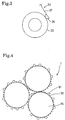
- larger external additive particles 91 function as spacers, that is, larger external additive particles 91 deposited on a toner matrix particle 95 substantially prevent smaller external additive particles 93 deposited on the same toner matrix particle 95 from directly contacting another toner matrix particle 95, and therefore substantially prevents the smaller external additive particles 93 from being sunk into the toner matrix particle 95.
- the embodiment employs a toner-empty sensor 55 that detects a limit of toner consumption, that is, a toner empty state, when toner still remains in the developing cartridge 36.
- the toner-empty sensor 55 is designed to detect the toner empty state when toner remains in the toner box 27 and the amount of toner remaining in the toner box 27 is equal to or greater than the amount of toner remaining in the developing chamber 51.
- the proportion of deteriorated toner to the entire amount of toner remaining in the developing chamber 51 is very high immediately before toner in the developing chamber 51 and the toner box 27 is completely consumed. If such toner is used for image development, various problems occur, for example, a filming on the photosensitive drum 21, and the like. However, if deteriorated toner is replaced with fresh toner when a certain amount of toner remains in the developing cartridge 36, image development through the use of toner having a high proportion of deteriorated toner immediately before complete consumption of toner is avoided. Therefore, image development can be constantly and stably performed without allowing occurrence of various problems as mentioned above, and the life span of the laser printer 1 can be increased.
- the light emitter 60 and the light receiver 61 of the toner-empty sensor 55 are disposed at positions relative to the toner box 27 where a portion of the toner box 27 having a capacity equal to or greater than the volume of toner containable in the developing chamber 51 is defined
- the light emitter 60 and the light receiver 61 may be disposed at any suitable positions as long as the positions allow the toner-empty sensor 55 to detect the toner empty state while toner exists even in a very small amount in the developing cartridge 36.
- the light emitter 60 and the light receiver 61 may be disposed at the developing chamber 51. Even in the case where the light emitter 60 and the light receiver 61 are disposed at the toner box 27, the positions thereof are not limited to positions as described above.
- a developing roller having a fluorine-based surface coat layer formed on an electrically conductive urethane rubber roller part was used.
- the aforementioned examples used a toner produced by mixing nigrosine as a charge control agent with a styrene-acryl polymerized toner and adding silica thereto.
- a toner containing a charge control resin as a charge control agent will be described below.
- Typical charge control resins are colorless and transparent, and therefore suitable for full-color development.
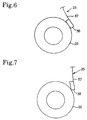
- the contact portion of the pressing portion 38 that contacts the developing roller 22 may have any shape, for example, a flat shape as shown in Fig. 6, as long as the contact portion does not include an angled portion. However, if the contact portion includes an angled portion as shown in Fig. 1, that is, if an angled portion of the pressing portion 38 contacts the developing roller 22 and toner although the configuration of the pressing portion 38 shown in Fig. 7 is the same as that shown in Fig. 6, the advantages mentioned above cannot be achieved.
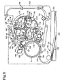
- Fig. 8 is a sectional view of portions of an embodiment of a color laser printer.
- Cyan, magenta, yellow and black positively electrically charged non-magnetic single-component toners are contained in the corresponding toner boxes 176 of the developing cartridges 177.
- Each toner is a polymerized toner as described above, and contains a charge control resin as described above. Since the charge control resin is colorless and transparent, the charge control resin can be used in the color toners containing corresponding coloring agents.
- the developing roller 173 of a developing cartridge 177 When the developing roller 173 of a developing cartridge 177 reaches such a position that the developing roller 173 of the cartridge 177 faces the photosensitive drum 168 as the rotatable developing unit 169 rotates, the positively electrically charged toner carried on the developing roller 173 contacts the photosensitive drum 168 as the developing roller 173 rotates. Thus, toner is transferred from the developing roller 173 onto the electrostatic latent image on the photosensitive drum 168, thereby visualizing the image. Image development is thus accomplished.
- the visualized image on the photosensitive drum 168 is transferred to the intermediate transfer drum 171.
- the intermediate transfer drum 171 is disposed in such a manner that the intermediate transfer drum 171 faces the photosensitive drum 168 and is rotatable.
- the intermediate transfer drum 171 is supplied with a predetermined transfer bias.
- the developing rollers 173 of the developing cartridges 177 sequentially come to face the photosensitive drum 168, so that a color image is formed on the intermediate transfer drum 171.
- the developing roller 173 of the cyan developing cartridge 177C comes to face the photosensitive drum 168 as the rotatable developing unit 169 rotates, the cyan toner from the cyan developing cartridge 177C is used to form on the photosensitive drum 168 a visible image, which is then transferred to the intermediate transfer drum 171.
- magenta toner from the magenta developing cartridge 177M is used to form on the photosensitive drum 168 a visible image, which is then transferred to the intermediate transfer drum 171, more specifically, superimposed on the cyan toner image on the intermediate transfer drum 171. Similar operations are repeated with the yellow toner from the yellow developing cartridge 177Y, and the black toner from the black developing cartridge 177K, to form a color image on the intermediate transfer drum 171.
- the color image is fixed while the print sheet 153 is passing between a heat roller 181 and a pressing roller 182 of the fixing unit 161 disposed downstream of the developing unit 160. After that, the print sheet 153 is conveyed by pairs of eject rollers 183, 184, 185, and is then ejected onto an output tray 186.
- the above embodiment employs the positively electrically charged toners, it is also possible to use negatively electrically charged toners. It is also possible to use pulverized toners instead of polymerized toners. If negatively electrically charged toners are used, it may be advisable that the toner contain a charge control resin having an anionic functional group.
- Toners as mentioned above are applicable not only to an intermediate-transfer laser printer as described above but also to a tandem type color laser printer.
- a developing device having components as described below was used.
- One type of layer thickness-regulating member was a silicone rubber member having a sectional shape of a semicircle of 3.5 mm in diameter and formed together with a stainless steel thin plate of 0.1 mm in thickness.
- Table 4 indicates that the layer thickness-regulating silicone rubber member caused almost no fogging. Visual observation of the pieces of tape stuck on the white paper verified that the silicone rubber member did not caused fogging.
Landscapes
- Physics & Mathematics (AREA)
- General Physics & Mathematics (AREA)
- Dry Development In Electrophotography (AREA)
- Developing Agents For Electrophotography (AREA)
- Photographic Developing Apparatuses (AREA)
- Color Electrophotography (AREA)
Abstract
Description
| Pressing force (gf/cm) | Number of sheets before blade wear-out | Print quality after 16000 sheets | Fog during initial print |
| 10 | 38000 | occurred | |
| 15 | 36000 | not occurred | |
| 20 | 35000 | not occurred | |
| 30 | 33000 | not occurred | |
| 40 | 31000 | not occurred | |
| 50 | 29000 | not occurred | |
| 60 | 28000 | not occurred | |
| 70 | 26000 | not occurred |
| Toner (9µm in mean particle size) | External additives: silica | Number of sheets before rubber wear-out | Print quality after 10000 sheets (before toner addition) |
| Polyester pulverized | BET200: 0.6wt.% | 2000 | |
| BET50: 1.0wt.% | |||
| Styrene-acryl polymerized | BET200: 0.6wt.% | 34000 | ▵: rough print, exposure defect |
| BET150: 1.0wt.% | |||
| Styrene-acryl polymerized | BET200: 0.6wt.% | 26000 | ▵: rough print |
| BET150: 1.0wt.% | |||
| Styrene-acryl polymerized | BET200: 0.6wt.% | 15000 | O |
| BET50: 1.0wt.% |
| Amount of remainder toner (g) | Total number of sheets printed before the filming on photosensitive drum |
| 0 | 5000 |
| 10 | 10000 |
| 30 | 15000 |
| 60 | 40000 |
| Material of layer thickness-regulating member | Reflectivity difference (ΔY) |
| Silicone rubber | 0.2 |
| Urethane rubber | 3.5 |
| Stainless steel | 3.0 |
Claims (14)
- A developing device comprising:a developing agent carrier that carries thereon a non-magnetic single-component developing agent; anda layer thickness-regulating member that presses a surface of the developing agent carrier, and forms a thin layer of the developing agent on the developing agent carrier,
wherein a pressing portion of the layer thickness-regulating member at which the layer thickness-regulating member presses the surface of the developing agent carrier is formed from a silicone rubber, and a pressing force with which the pressing portion presses the surface of the developing agent carrier is within a range of approximately 15 gf/cm to approximately 30 gf/cm. - A developing device comprising:a developing agent carrier that carries thereon a non-magnetic single-component developing agent; anda layer thickness-regulating member that presses a surface of the developing agent carrier, and that forms a thin layer of the developing agent on the developing agent carrier,
wherein a pressing portion of the layer thickness-regulating member at which the layer thickness-regulating member presses the surface of the developing agent carrier is formed from a silicone rubber. - The developing device according to claim 1 or 2, wherein the surface of the developing agent carrier is formed from an electrically conductive elastic material, preferably being one of urethane rubber or silicone rubber, and/or containing fluorine.
- The device according to one of claims 1 to 3, wherein the developing agent is a polymerized toner produced by polymerizing a polymerizable monomer, preferably containing at least two kinds of external additives that are different in particle size.
- The device according to claim 4, wherein the external additive having a relatively large particle size from the other kind of external additive, has a BET specific surface area that is less than 100 m2/g or the at least two kinds of external additives include an external additive having a BET specific surface area of 200 m2/g and an external additive having a BET specific surface area of 50 m2/g.
- The device according to one of claims 1 to 5, wherein a surface roughness of the surface of the developing agent carrier is less than a mean particle size of the developing agent.
- The device according to one of claims 1 to 6, wherein the developing agent contains a charge control resin for providing an electrical charging characteristic, preferably being a resin produced by copolymerizing an ionic monomer having an ionic functional group, and a copolymerizable monomer that is copolymerizable with the ionic monomer, the ionic function group including a quarternary ammonium salt, and the copolymerizable monomer including a styrene-based monomer and an acryl-based monomer.
- A cartridge comprising:a developing agent storage chamber that contains a non-magnetic single-component developing agent;a developing agent carrier that carries thereon the non-magnetic single-component developing agent;a supplying member that supplies the developing agent from the developing agent storage chamber to the developing agent carrier; anda layer thickness-regulating member that presses a surface of the developing agent carrier, and forms a thin layer of the developing agent on the developing agent carrier,
wherein a pressing portion of the layer thickness-regulating member at which the layer thickness-regulating member presses the surface of the developing agent carrier is formed from a silicone rubber, and a pressing force with which the pressing portion presses the surface of the developing agent carrier is within a range of about 15 gf/cm to about 30 gf/cm. - The cartridge according to claim 8, wherein the developing agent is a polymerized toner produced by polymerizing a polymerizable monomer.
- The cartridge according to claim 8 or 9, wherein the cartridge is detachably removable from a cartridge that includes a photosensitive drum.
- An image forming apparatus comprising:a cartridge according to claim 8, andan electrostatic latent image carrier being disposed facing the developing agent carrier, wherein an electrostatic latent image is formed on the electrostatic latent image carrier.
- An image forming apparatus, comprising:a developing agent storage chamber that contains a non-magnetic single-component developing agent;a developing agent carrier that carries thereon the non-magnetic single-component developing agent;a supplying member that supplies the developing agent from the developing agent storage chamber to the developing agent carrier;a layer thickness-regulating member that presses a surface of the developing agent carrier, and forms a thin layer of the developing agent on the developing agent carrier;a developing chamber that contains the developing agent carrier and the layer thickness-regulating member, and an opening portion via which the developing agent storage chamber and the developing chamber communicate with each other; anda developing agent amount detector that detects a state that an amount of the developing agent remaining in the developing agent storage chamber is substantially equal to an amount of the developing agent that is allowed to exist in the developing chamber.
- The apparatus according to claim 11 or 12, wherein the developing agent is a polymerized toner produced by polymerizing a polymerizable monomer.
- The image forming apparatus according to one of claims 11 to 13, the cartridge further comprising a developing chamber that contains the developing agent carrier and the layer thickness-regulating member, and an opening portion via which the developing agent storage chamber and the developing chamber communicate with each other,the apparatus preferably comprising a developing agent amount detector that detects a state that an amount of the developing agent remaining in the developing agent storage chamber is substantially equal to or greater than, respectively an amount of the developing agent that is allowed to exist in the developing chamber.
Applications Claiming Priority (8)
| Application Number | Priority Date | Filing Date | Title |
|---|---|---|---|
| JP6503499 | 1999-03-11 | ||
| JP6503499A JP2000258995A (en) | 1999-03-11 | 1999-03-11 | Developing device and image forming device |
| JP7144699A JP2000267435A (en) | 1999-03-17 | 1999-03-17 | Developing device and image forming device |
| JP7144699 | 1999-03-17 | ||
| JP7856999A JP4085507B2 (en) | 1999-03-23 | 1999-03-23 | Image forming apparatus |
| JP7856999 | 1999-03-23 | ||
| JP11084021A JP2000275963A (en) | 1999-03-26 | 1999-03-26 | Image forming apparatus and developing cartridge |
| JP8402199 | 1999-03-26 |
Publications (3)
| Publication Number | Publication Date |
|---|---|
| EP1037119A2 true EP1037119A2 (en) | 2000-09-20 |
| EP1037119A3 EP1037119A3 (en) | 2000-12-13 |
| EP1037119B1 EP1037119B1 (en) | 2004-12-01 |
Family
ID=27464532
Family Applications (1)
| Application Number | Title | Priority Date | Filing Date |
|---|---|---|---|
| EP00104143A Expired - Lifetime EP1037119B1 (en) | 1999-03-11 | 2000-02-29 | Developer device with toner layer thickness regulating member, cartridge and image forming apparatus comprising such device |
Country Status (5)
| Country | Link |
|---|---|
| US (1) | US6256471B1 (en) |
| EP (1) | EP1037119B1 (en) |
| CN (1) | CN1199087C (en) |
| AT (1) | ATE284051T1 (en) |
| DE (1) | DE60016299T2 (en) |
Families Citing this family (12)
| Publication number | Priority date | Publication date | Assignee | Title |
|---|---|---|---|---|
| US6404671B1 (en) * | 2001-08-21 | 2002-06-11 | International Business Machines Corporation | Data-dependent field compensation for writing magnetic random access memories |
| JP2003270937A (en) * | 2002-03-15 | 2003-09-25 | Brother Ind Ltd | Developing device and image forming device |
| JP4096783B2 (en) * | 2003-03-28 | 2008-06-04 | ブラザー工業株式会社 | Developing device and image forming apparatus |
| JP4402391B2 (en) * | 2003-07-17 | 2010-01-20 | キヤノン株式会社 | Development device |
| US7462146B2 (en) * | 2003-08-29 | 2008-12-09 | Canon Kabushiki Kaisha | Roller member, and process for its manufacture |
| US7013104B2 (en) | 2004-03-12 | 2006-03-14 | Lexmark International, Inc. | Toner regulating system having toner regulating member with metallic coating on flexible substrate |
| US7236729B2 (en) | 2004-07-27 | 2007-06-26 | Lexmark International, Inc. | Electrophotographic toner regulating member with induced strain outside elastic response region |
| DE602006021255D1 (en) * | 2005-04-26 | 2011-05-26 | Brother Ind Ltd | A development cartridge for an image forming apparatus |
| US7424253B2 (en) * | 2005-08-22 | 2008-09-09 | Lexmark International, Inc. | Toner metering device |
| JP2008209756A (en) * | 2007-02-27 | 2008-09-11 | Brother Ind Ltd | Image forming apparatus |
| JP5056896B2 (en) | 2010-05-14 | 2012-10-24 | ブラザー工業株式会社 | Image forming apparatus |
| JP6131830B2 (en) * | 2013-10-31 | 2017-05-24 | ブラザー工業株式会社 | Image forming apparatus |
Family Cites Families (20)
| Publication number | Priority date | Publication date | Assignee | Title |
|---|---|---|---|---|
| DE69015403T2 (en) * | 1989-03-31 | 1995-07-13 | Tokyo Electric Co Ltd | Development process and device. |
| JPH0774920B2 (en) * | 1989-11-30 | 1995-08-09 | 三田工業株式会社 | Charge control resin particles and method for producing the same |
| SG43303A1 (en) * | 1991-04-10 | 1997-10-17 | Canon Kk | Process cartridge recording apparatus and method for assembling process cartridge |
| EP0523654B1 (en) * | 1991-07-16 | 1997-03-05 | Canon Kabushiki Kaisha | Toner for developing electrostatic image |
| JPH0534982A (en) * | 1991-08-02 | 1993-02-12 | Mita Ind Co Ltd | Toner for developing electrostatic charge image |
| JP3086763B2 (en) * | 1993-03-09 | 2000-09-11 | 株式会社東芝 | Image forming device |
| DE69407454T3 (en) * | 1993-03-15 | 2001-04-12 | Kao Corp., Tokio/Tokyo | Development process with non-magnetic one-component developer |
| JP3235898B2 (en) * | 1993-03-22 | 2001-12-04 | 花王株式会社 | Positively chargeable toner and non-magnetic one-component developing method |
| JPH0659528A (en) * | 1993-05-31 | 1994-03-04 | Canon Inc | Image forming system |
| JPH0822140A (en) * | 1994-07-08 | 1996-01-23 | Matsushita Electric Ind Co Ltd | Electrophotography method |
| JP3221292B2 (en) * | 1995-08-23 | 2001-10-22 | 富士通株式会社 | Developer thickness regulating blade, method of manufacturing the same, and image forming apparatus using the same |
| JPH09146370A (en) * | 1995-11-22 | 1997-06-06 | Brother Ind Ltd | Image forming apparatus and toner for the image forming apparatus |
| JPH09160380A (en) * | 1995-12-12 | 1997-06-20 | Nippon Zeon Co Ltd | Developing blade, developing device, and image forming apparatus |
| JP3348370B2 (en) * | 1996-05-31 | 2002-11-20 | 京セラミタ株式会社 | Image forming machine process unit |
| JPH1010784A (en) * | 1996-06-27 | 1998-01-16 | Brother Ind Ltd | Positively chargeable one-component developer and image forming apparatus using the developer |
| US6049688A (en) * | 1996-09-30 | 2000-04-11 | Matsushita Electric Industrial Co., Ltd. | Toner layer forming device for non-magnetic toner |
| JP3774970B2 (en) * | 1997-01-30 | 2006-05-17 | コニカミノルタホールディングス株式会社 | Toner for electrostatic latent image development, developer and image forming method |
| JPH10228168A (en) * | 1997-02-17 | 1998-08-25 | Canon Inc | Developing device |
| JPH11133736A (en) * | 1997-10-30 | 1999-05-21 | Hitachi Ltd | Developing device |
| JP4000209B2 (en) * | 1997-12-17 | 2007-10-31 | 富士ゼロックス株式会社 | Toner for electrostatic latent image developer, method for producing toner for electrostatic latent image developer, electrostatic latent image developer, and image forming method |
-
2000
- 2000-02-29 EP EP00104143A patent/EP1037119B1/en not_active Expired - Lifetime
- 2000-02-29 DE DE60016299T patent/DE60016299T2/en not_active Expired - Lifetime
- 2000-02-29 AT AT00104143T patent/ATE284051T1/en not_active IP Right Cessation
- 2000-03-01 US US09/516,765 patent/US6256471B1/en not_active Expired - Lifetime
- 2000-03-13 CN CN00104029.4A patent/CN1199087C/en not_active Expired - Lifetime
Also Published As
| Publication number | Publication date |
|---|---|
| HK1030994A1 (en) | 2001-05-25 |
| CN1199087C (en) | 2005-04-27 |
| ATE284051T1 (en) | 2004-12-15 |
| DE60016299T2 (en) | 2005-11-10 |
| US6256471B1 (en) | 2001-07-03 |
| EP1037119B1 (en) | 2004-12-01 |
| EP1037119A3 (en) | 2000-12-13 |
| CN1267003A (en) | 2000-09-20 |
| DE60016299D1 (en) | 2005-01-05 |
Similar Documents
| Publication | Publication Date | Title |
|---|---|---|
| CN1828446B (en) | Image forming apparatus and developer cartridge used therein | |
| JP4310702B2 (en) | Image forming apparatus | |
| EP1037119B1 (en) | Developer device with toner layer thickness regulating member, cartridge and image forming apparatus comprising such device | |
| JP2003330320A (en) | Image forming device | |
| JP2006267994A (en) | Image forming apparatus and developing cartridge | |
| US7773923B2 (en) | Developing apparatus and image forming apparatus | |
| EP1033630A2 (en) | Developing apparatus and image forming apparatus | |
| US20040052557A1 (en) | Processing device and image forming apparatus | |
| JP5169799B2 (en) | Lubricant coating apparatus, process cartridge, and image forming apparatus | |
| JP4462328B2 (en) | Developing device, image forming apparatus, and image forming method | |
| US6470153B2 (en) | Developing device and developing method featuring a use-related control of a first voltage and a second voltage respectively, applied to a developer bearing member and a developer charging member | |
| JPH10228168A (en) | Developing device | |
| US20200333726A1 (en) | Developer bearing member, developing apparatus, process cartridge, and image forming apparatus | |
| JP4546552B2 (en) | Image forming apparatus | |
| CN100504638C (en) | Developing regulating member and developing device | |
| EP1154332A2 (en) | Developing device | |
| JP4085507B2 (en) | Image forming apparatus | |
| JP5049482B2 (en) | Image forming apparatus | |
| CN101339389B (en) | Image forming apparatus | |
| US7209691B2 (en) | Developing device and image forming apparatus | |
| JP5121539B2 (en) | Developing device and image forming apparatus | |
| JP2001100520A (en) | Developing device and image forming device | |
| JP2002351134A (en) | Image forming device | |
| JP2000267435A (en) | Developing device and image forming device | |
| JP2024071331A (en) | Developing device and image forming apparatus equipped with same |
Legal Events
| Date | Code | Title | Description |
|---|---|---|---|
| PUAI | Public reference made under article 153(3) epc to a published international application that has entered the european phase |
Free format text: ORIGINAL CODE: 0009012 |
|
| AK | Designated contracting states |
Kind code of ref document: A2 Designated state(s): AT BE CH CY DE DK ES FI FR GB GR IE IT LI LU MC NL PT SE |
|
| AX | Request for extension of the european patent |
Free format text: AL;LT;LV;MK;RO;SI |
|
| PUAL | Search report despatched |
Free format text: ORIGINAL CODE: 0009013 |
|
| AK | Designated contracting states |
Kind code of ref document: A3 Designated state(s): AT BE CH CY DE DK ES FI FR GB GR IE IT LI LU MC NL PT SE |
|
| AX | Request for extension of the european patent |
Free format text: AL;LT;LV;MK;RO;SI |
|
| 17P | Request for examination filed |
Effective date: 20010522 |
|
| 17Q | First examination report despatched |
Effective date: 20010720 |
|
| AKX | Designation fees paid |
Free format text: AT BE CH CY DE DK ES FI FR GB GR IE IT LI LU MC NL PT SE |
|
| RTI1 | Title (correction) |
Free format text: DEVELOPER DEVICE WITH TONER LAYER THICKNESS REGULATING MEMBER, CARTRIDGE AND IMAGE FORMING APPARATUS COMPRISING SUCH DEVI |
|
| GRAP | Despatch of communication of intention to grant a patent |
Free format text: ORIGINAL CODE: EPIDOSNIGR1 |
|
| RTI1 | Title (correction) |
Free format text: DEVELOPER DEVICE WITH TONER LAYER THICKNESS REGULATING MEMBER, CARTRIDGE AND IMAGE FORMING APPARATUS COMPRISING SUCH DEVI |
|
| GRAS | Grant fee paid |
Free format text: ORIGINAL CODE: EPIDOSNIGR3 |
|
| GRAA | (expected) grant |
Free format text: ORIGINAL CODE: 0009210 |
|
| AK | Designated contracting states |
Kind code of ref document: B1 Designated state(s): AT BE CH CY DE DK ES FI FR GB GR IE IT LI LU MC NL PT SE |
|
| PG25 | Lapsed in a contracting state [announced via postgrant information from national office to epo] |
Ref country code: FI Free format text: LAPSE BECAUSE OF FAILURE TO SUBMIT A TRANSLATION OF THE DESCRIPTION OR TO PAY THE FEE WITHIN THE PRESCRIBED TIME-LIMIT Effective date: 20041201 Ref country code: NL Free format text: LAPSE BECAUSE OF FAILURE TO SUBMIT A TRANSLATION OF THE DESCRIPTION OR TO PAY THE FEE WITHIN THE PRESCRIBED TIME-LIMIT Effective date: 20041201 Ref country code: AT Free format text: LAPSE BECAUSE OF FAILURE TO SUBMIT A TRANSLATION OF THE DESCRIPTION OR TO PAY THE FEE WITHIN THE PRESCRIBED TIME-LIMIT Effective date: 20041201 Ref country code: IT Free format text: LAPSE BECAUSE OF FAILURE TO SUBMIT A TRANSLATION OF THE DESCRIPTION OR TO PAY THE FEE WITHIN THE PRESCRIBED TIME-LIMIT;WARNING: LAPSES OF ITALIAN PATENTS WITH EFFECTIVE DATE BEFORE 2007 MAY HAVE OCCURRED AT ANY TIME BEFORE 2007. THE CORRECT EFFECTIVE DATE MAY BE DIFFERENT FROM THE ONE RECORDED. Effective date: 20041201 |
|
| REG | Reference to a national code |
Ref country code: GB Ref legal event code: FG4D |
|
| REG | Reference to a national code |
Ref country code: CH Ref legal event code: EP |
|
| REG | Reference to a national code |
Ref country code: IE Ref legal event code: FG4D |
|
| REF | Corresponds to: |
Ref document number: 60016299 Country of ref document: DE Date of ref document: 20050105 Kind code of ref document: P |
|
| PG25 | Lapsed in a contracting state [announced via postgrant information from national office to epo] |
Ref country code: IE Free format text: LAPSE BECAUSE OF NON-PAYMENT OF DUE FEES Effective date: 20050228 Ref country code: CY Free format text: LAPSE BECAUSE OF FAILURE TO SUBMIT A TRANSLATION OF THE DESCRIPTION OR TO PAY THE FEE WITHIN THE PRESCRIBED TIME-LIMIT Effective date: 20050228 Ref country code: LU Free format text: LAPSE BECAUSE OF NON-PAYMENT OF DUE FEES Effective date: 20050228 |
|
| REG | Reference to a national code |
Ref country code: CH Ref legal event code: NV Representative=s name: R. A. EGLI & CO. PATENTANWAELTE |
|
| PG25 | Lapsed in a contracting state [announced via postgrant information from national office to epo] |
Ref country code: DK Free format text: LAPSE BECAUSE OF FAILURE TO SUBMIT A TRANSLATION OF THE DESCRIPTION OR TO PAY THE FEE WITHIN THE PRESCRIBED TIME-LIMIT Effective date: 20050301 Ref country code: SE Free format text: LAPSE BECAUSE OF FAILURE TO SUBMIT A TRANSLATION OF THE DESCRIPTION OR TO PAY THE FEE WITHIN THE PRESCRIBED TIME-LIMIT Effective date: 20050301 Ref country code: GR Free format text: LAPSE BECAUSE OF FAILURE TO SUBMIT A TRANSLATION OF THE DESCRIPTION OR TO PAY THE FEE WITHIN THE PRESCRIBED TIME-LIMIT Effective date: 20050301 |
|
| PG25 | Lapsed in a contracting state [announced via postgrant information from national office to epo] |
Ref country code: ES Free format text: LAPSE BECAUSE OF FAILURE TO SUBMIT A TRANSLATION OF THE DESCRIPTION OR TO PAY THE FEE WITHIN THE PRESCRIBED TIME-LIMIT Effective date: 20050312 |
|
| PG25 | Lapsed in a contracting state [announced via postgrant information from national office to epo] |
Ref country code: MC Free format text: LAPSE BECAUSE OF NON-PAYMENT OF DUE FEES Effective date: 20050331 |
|
| NLV1 | Nl: lapsed or annulled due to failure to fulfill the requirements of art. 29p and 29m of the patents act | ||
| ET | Fr: translation filed | ||
| PLBE | No opposition filed within time limit |
Free format text: ORIGINAL CODE: 0009261 |
|
| STAA | Information on the status of an ep patent application or granted ep patent |
Free format text: STATUS: NO OPPOSITION FILED WITHIN TIME LIMIT |
|
| 26N | No opposition filed |
Effective date: 20050902 |
|
| REG | Reference to a national code |
Ref country code: IE Ref legal event code: MM4A |
|
| PG25 | Lapsed in a contracting state [announced via postgrant information from national office to epo] |
Ref country code: PT Free format text: LAPSE BECAUSE OF NON-PAYMENT OF DUE FEES Effective date: 20050501 |
|
| REG | Reference to a national code |
Ref country code: FR Ref legal event code: PLFP Year of fee payment: 17 |
|
| REG | Reference to a national code |
Ref country code: FR Ref legal event code: PLFP Year of fee payment: 18 |
|
| REG | Reference to a national code |
Ref country code: FR Ref legal event code: PLFP Year of fee payment: 19 |
|
| PGFP | Annual fee paid to national office [announced via postgrant information from national office to epo] |
Ref country code: DE Payment date: 20190115 Year of fee payment: 20 Ref country code: FR Payment date: 20190117 Year of fee payment: 20 Ref country code: GB Payment date: 20190128 Year of fee payment: 20 Ref country code: CH Payment date: 20190125 Year of fee payment: 20 |
|
| PGFP | Annual fee paid to national office [announced via postgrant information from national office to epo] |
Ref country code: BE Payment date: 20190218 Year of fee payment: 20 |
|
| REG | Reference to a national code |
Ref country code: DE Ref legal event code: R071 Ref document number: 60016299 Country of ref document: DE |
|
| REG | Reference to a national code |
Ref country code: CH Ref legal event code: PL |
|
| REG | Reference to a national code |
Ref country code: GB Ref legal event code: PE20 Expiry date: 20200228 |
|
| REG | Reference to a national code |
Ref country code: BE Ref legal event code: MK Effective date: 20200229 |
|
| PG25 | Lapsed in a contracting state [announced via postgrant information from national office to epo] |
Ref country code: GB Free format text: LAPSE BECAUSE OF EXPIRATION OF PROTECTION Effective date: 20200228 |