EP1036999A1 - Method and apparatus for pasteurizing fluids - Google Patents
Method and apparatus for pasteurizing fluids Download PDFInfo
- Publication number
- EP1036999A1 EP1036999A1 EP00200782A EP00200782A EP1036999A1 EP 1036999 A1 EP1036999 A1 EP 1036999A1 EP 00200782 A EP00200782 A EP 00200782A EP 00200782 A EP00200782 A EP 00200782A EP 1036999 A1 EP1036999 A1 EP 1036999A1
- Authority
- EP
- European Patent Office
- Prior art keywords
- fluid
- heat transfer
- transfer device
- photographic processing
- processing solution
- Prior art date
- Legal status (The legal status is an assumption and is not a legal conclusion. Google has not performed a legal analysis and makes no representation as to the accuracy of the status listed.)
- Granted
Links
- 239000012530 fluid Substances 0.000 title claims abstract description 119
- 238000000034 method Methods 0.000 title claims abstract description 31
- 238000012546 transfer Methods 0.000 claims abstract description 57
- 238000012545 processing Methods 0.000 claims abstract description 39
- 238000009928 pasteurization Methods 0.000 claims abstract description 20
- 238000004891 communication Methods 0.000 claims abstract description 6
- 239000000243 solution Substances 0.000 claims description 47
- 238000013461 design Methods 0.000 claims description 4
- 238000004061 bleaching Methods 0.000 claims description 2
- 239000012487 rinsing solution Substances 0.000 claims description 2
- 230000000087 stabilizing effect Effects 0.000 claims description 2
- 239000000126 substance Substances 0.000 abstract description 8
- XLYOFNOQVPJJNP-UHFFFAOYSA-N water Substances O XLYOFNOQVPJJNP-UHFFFAOYSA-N 0.000 description 13
- 239000000463 material Substances 0.000 description 7
- 238000001816 cooling Methods 0.000 description 6
- 239000004065 semiconductor Substances 0.000 description 6
- 235000013305 food Nutrition 0.000 description 5
- 238000011282 treatment Methods 0.000 description 4
- 238000001704 evaporation Methods 0.000 description 3
- 230000008020 evaporation Effects 0.000 description 3
- 238000010438 heat treatment Methods 0.000 description 3
- 241000233866 Fungi Species 0.000 description 2
- 239000007864 aqueous solution Substances 0.000 description 2
- 239000003139 biocide Substances 0.000 description 2
- 238000001311 chemical methods and process Methods 0.000 description 2
- 238000004140 cleaning Methods 0.000 description 2
- 239000013256 coordination polymer Substances 0.000 description 2
- 230000001351 cycling effect Effects 0.000 description 2
- 238000007599 discharging Methods 0.000 description 2
- 238000005516 engineering process Methods 0.000 description 2
- 230000000813 microbial effect Effects 0.000 description 2
- 238000005086 pumping Methods 0.000 description 2
- 230000005855 radiation Effects 0.000 description 2
- 229910052709 silver Inorganic materials 0.000 description 2
- 239000004332 silver Substances 0.000 description 2
- 239000003381 stabilizer Substances 0.000 description 2
- 230000001954 sterilising effect Effects 0.000 description 2
- 238000004659 sterilization and disinfection Methods 0.000 description 2
- 241000894006 Bacteria Species 0.000 description 1
- RYGMFSIKBFXOCR-UHFFFAOYSA-N Copper Chemical compound [Cu] RYGMFSIKBFXOCR-UHFFFAOYSA-N 0.000 description 1
- 230000005679 Peltier effect Effects 0.000 description 1
- 230000002411 adverse Effects 0.000 description 1
- 238000000429 assembly Methods 0.000 description 1
- 230000000712 assembly Effects 0.000 description 1
- 230000015572 biosynthetic process Effects 0.000 description 1
- 238000009835 boiling Methods 0.000 description 1
- 238000009395 breeding Methods 0.000 description 1
- 230000001488 breeding effect Effects 0.000 description 1
- 239000012141 concentrate Substances 0.000 description 1
- 238000009833 condensation Methods 0.000 description 1
- 230000005494 condensation Effects 0.000 description 1
- 230000001276 controlling effect Effects 0.000 description 1
- 229910052802 copper Inorganic materials 0.000 description 1
- 239000010949 copper Substances 0.000 description 1
- 230000001419 dependent effect Effects 0.000 description 1
- 230000000694 effects Effects 0.000 description 1
- 238000002474 experimental method Methods 0.000 description 1
- 238000001914 filtration Methods 0.000 description 1
- 230000005484 gravity Effects 0.000 description 1
- 231100001261 hazardous Toxicity 0.000 description 1
- 229910001385 heavy metal Inorganic materials 0.000 description 1
- 238000007654 immersion Methods 0.000 description 1
- 230000002401 inhibitory effect Effects 0.000 description 1
- 230000000670 limiting effect Effects 0.000 description 1
- 244000005700 microbiome Species 0.000 description 1
- 239000008267 milk Substances 0.000 description 1
- 210000004080 milk Anatomy 0.000 description 1
- 235000013336 milk Nutrition 0.000 description 1
- 230000002572 peristaltic effect Effects 0.000 description 1
- 238000009428 plumbing Methods 0.000 description 1
- 238000004321 preservation Methods 0.000 description 1
- 230000002829 reductive effect Effects 0.000 description 1
- 238000005057 refrigeration Methods 0.000 description 1
- 230000001105 regulatory effect Effects 0.000 description 1
Images


Classifications
-
- G—PHYSICS
- G03—PHOTOGRAPHY; CINEMATOGRAPHY; ANALOGOUS TECHNIQUES USING WAVES OTHER THAN OPTICAL WAVES; ELECTROGRAPHY; HOLOGRAPHY
- G03D—APPARATUS FOR PROCESSING EXPOSED PHOTOGRAPHIC MATERIALS; ACCESSORIES THEREFOR
- G03D3/00—Liquid processing apparatus involving immersion; Washing apparatus involving immersion
- G03D3/02—Details of liquid circulation
- G03D3/06—Liquid supply; Liquid circulation outside tanks
-
- F—MECHANICAL ENGINEERING; LIGHTING; HEATING; WEAPONS; BLASTING
- F25—REFRIGERATION OR COOLING; COMBINED HEATING AND REFRIGERATION SYSTEMS; HEAT PUMP SYSTEMS; MANUFACTURE OR STORAGE OF ICE; LIQUEFACTION SOLIDIFICATION OF GASES
- F25B—REFRIGERATION MACHINES, PLANTS OR SYSTEMS; COMBINED HEATING AND REFRIGERATION SYSTEMS; HEAT PUMP SYSTEMS
- F25B21/00—Machines, plants or systems, using electric or magnetic effects
- F25B21/02—Machines, plants or systems, using electric or magnetic effects using Peltier effect; using Nernst-Ettinghausen effect
-
- G—PHYSICS
- G03—PHOTOGRAPHY; CINEMATOGRAPHY; ANALOGOUS TECHNIQUES USING WAVES OTHER THAN OPTICAL WAVES; ELECTROGRAPHY; HOLOGRAPHY
- G03D—APPARATUS FOR PROCESSING EXPOSED PHOTOGRAPHIC MATERIALS; ACCESSORIES THEREFOR
- G03D13/00—Processing apparatus or accessories therefor, not covered by groups G11B3/00 - G11B11/00
- G03D13/006—Temperature control of the developer
-
- H—ELECTRICITY
- H10—SEMICONDUCTOR DEVICES; ELECTRIC SOLID-STATE DEVICES NOT OTHERWISE PROVIDED FOR
- H10N—ELECTRIC SOLID-STATE DEVICES NOT OTHERWISE PROVIDED FOR
- H10N10/00—Thermoelectric devices comprising a junction of dissimilar materials, i.e. devices exhibiting Seebeck or Peltier effects
- H10N10/10—Thermoelectric devices comprising a junction of dissimilar materials, i.e. devices exhibiting Seebeck or Peltier effects operating with only the Peltier or Seebeck effects
- H10N10/17—Thermoelectric devices comprising a junction of dissimilar materials, i.e. devices exhibiting Seebeck or Peltier effects operating with only the Peltier or Seebeck effects characterised by the structure or configuration of the cell or thermocouple forming the device
Definitions
- the present invention relates to a method for treating aqueous fluids, such as photographic processing solutions, to control biogrowth.
- aqueous fluids such as photographic processing solutions
- this invention provides a method for sterilizing such solutions.
- the invention also relates to a heat transfer apparatus that can be used in the noted method. This invention has utility in the photographic, chemical food processing and health industries.
- Biogrowth that is growth of bacteria and/or fungus, can be a problem for many reasons of health, safety and quality in the food, chemical, photographic and health industries.
- pasteurization involves exposure to high temperatures for a relatively brief time.
- bulk pasteurization the process typically involves heating a fluid to about 65°C for 30 minutes.
- flash pasteurization the fluid is heated to a higher temperature (over 70°C) for much less time (for example, 15 seconds).
- Thermoelectric refrigeration is a known technology [ CRC Handbook of Thermoelectrics , Rowe (Ed.), CRC Press, Inc., 1995, pp. 597-676].
- This technique involves passing a current through one or more pairs of n- and p-type semiconductor materials, providing both hot and cold sides that can be contacted with fluids to be treated.
- direct current passes from the n- to the p-type semiconductor material and heat is absorbed from the environment (in this case, the treated fluid).
- the adsorbed heat is transferred through the semiconductor materials by electron transport to the other side of the junction and liberated as electrons return to a lower energy level in the p-type material.
- This phenomenon is called the Peltier effect, and devices used in this manner are often called Peltier heat transfer devices.
- More than one pair of semiconductors are usually assembled together to form single or multistage thermoelectric modules.
- a Peltier heat device is used in conjunction with photographic film processors that utilize both a developer bath and a water wash bath. During use of the heat device, the developer is cooled while the water wash is heated.
- thermoelectric Peltier heat transfer device having a cold side and a hot side that are in direct fluid flow communication so that the same fluid is treated on both the cold and hot sides of the heat transfer device.
- This heat transfer device can be used in a method for treating a fluid comprising the steps of:
- thermoelectric Peltier heat transfer device having a cold side and a hot side that are in direct fluid flow communication so that the same photographic processing solution is treated on both the cold and hot sides of the heat transfer device, comprising the steps of:
- the device and method of this invention can be used to sterilize the treated fluid on one side of the heat transfer device (the hot side) by flash pasteurization, and then rapidly cool the treated fluid to an appropriate temperature using the cold side of the same device.
- the same fluid is contacted simultaneously with both hot and cold sides of the thermoelectric Peltier heat transfer device.
- the hot and cold sides are connected in a suitable fashion to provide "direct" fluid flow communication without intervening tanks, compartments or treatments.
- the treated fluid passes directly from the hot side of the heat transfer device to the cold side.
- Flash pasteurization on the hot side of the device kills any microorganisms and fungi present in the fluid.
- the treated solution can be returned to the processing tank without substantial change in temperature within a few seconds of treatment. Substantially no fluid is lost in the method because little evaporation occurs during flash pasteurization in the closed system of the invention.
- the heat transfer device and method of this invention allow pasteurization without interruption of photoprocessing or other chemical processes in which the treated fluids are used. This advantage is usually transparent to the actual users since the fluid leaves and re-enters a processing tank (or other fluid reservoir) at nearly the same temperature, and the device and fluid connections can be hidden from view, thereby providing additional safety features.
- hot side and cold side of the device of this invention we mean that the hot side of the device is a source of heat for heating up the treated fluid. Thus, the fluid becomes a heat sink on the hot side of the device.
- cold side of the device refers to a side that absorbs heat from the treated fluid, thereby cooling the fluid. Thus, the fluid is a heat source for the cold side.
- the method of the present invention uses flash pasteurization to rapidly heat a fluid to kill any biogrowth that is present. Yet, because the fluid is at high temperatures for only brief periods of time, the possibility of adverse effects on the fluid are minimized. Since the fluid is heated and cooled in a small, well-insulated device, the efficiency of the method is far greater than if the fluid was heated and cooled in bulk in a large container of some type (such as processing tank or vat). No net evaporation of the fluid occurs since it is treated in a closed environment.
- the heat transfer device of the invention presents several additional advantages. It can be designed so that operators are shielded from the temperature extremes used to treat the fluid, and it is small in size compared to more traditional heat exchangers. It can be readily integrated into various processing systems, such as for food, chemical, photographic, or health processes.
- aqueous fluids from various industries can be treated in the practice of this invention, it is particularly advantageous for the photographic industry where photographic (or photochemical) processing solutions are treated in-line to control biogrowth in the various processing tanks.
- processing solutions include, but are not limited to, color developing solutions, bleaching solutions, bleach-fixing solutions, fixing solutions, prebleaching, stabilizing solutions, final rinsing solutions and others readily apparent to one skilled in the photographic processing art.
- the treated processing solutions can be the working strength solutions, concentrates, replenishers, regenerators or make-up water used in replenishment.
- the treated fluid is contacted with the hot side of the heat-transfer device for a residence time sufficient for flash pasteurization.
- This residence time will vary with the particular chemical process in which the treated fluid is used, device design and dimensions, desired operating temperatures, and fluid properties.
- most fluids will be in contact with the hot side for at least 5 seconds, and preferably at least 15 seconds.
- contact with the hot side will generally be for at least 10 seconds, and preferably for at least 20 seconds.
- the maximum contact time will vary depending upon the particular fluid to be treated.
- Residence time for contact with the cold side of the heat transfer device can be any suitable time needed to cool the treated fluid to the desired temperature. It can be the same or different as the residence time for the hot side.
- Residence time can be varied by using various fluid flow channels or patterns (see for example FIGS. 4-6 as discussed below) or by varying the fluid flow velocity or turbulence using appropriate pumping or other fluid moving means, or obstructions in the fluid flow channels.
- Pasteurization is a known process in various industries, including the food industry to kill biogrowth in milk, and is described for example in more detail in Principles and Practice of Disinfection, Preservation, and Sterilization , (2nd Ed.), Russell, Hugo and Ayliffe (Eds.), Blackwell Scientific Publications, 1992, pp. 494-495, and in the McGraw-Hill Encyclopedia of Science and Technology , (7th Ed.), 1992, page 172. It involves a rapid heating and immediate rapid cooling of the fluid. Its use in the present invention is modified from conventional procedures in that the fluid is not treated in bulk, but in a fluid stream taken out of the process and which can be returned after treatment.
- the temperatures needed for practicing the present invention will also vary with the residence time, but generally, the treated fluid temperature is raised to at least 65°C, and preferably at least 70°C by contact with the hot side of the heat transfer device.
- the maximum and optimum temperatures can be readily determined by routine experimentation, taking in account the pattern of the fluid flow channel, residence time on the heat-emitting side of the device, fluid volume and other factors. For example, one set of useful conditions would be to treat a fluid to raise its temperature to from about 70 to about 80°C for from about 15 seconds to about 2 minutes.
- the fluid is directly passed into contact with a cold side of the heat transfer device for immediate and rapid cooling.
- the time for cooling will vary depending upon the volume of fluid, the temperature it has been heated to, the desired cooled temperature, and the fluid flow pattern. This is achieved by having the hot and cold sides in "direct fluid flow communication" which means that the fluid is not passed through compartment, tanks or otherwise collected or treated between flash pasteurization and cooling.
- the fluid is passed directly from the hot side of the device to the cold side by plumbing that directly connects the fluid flow channel of one side to the fluid flow channel of the other. Fluid can be moved through the device using suitable pumps, gravity or other means.
- the heat transfer devices used in the practice of the present invention are what are known as Peltier heat transfer devices that are described in various publications, i ncluding CRC Handbook of Thermoelectics , Rowe (Ed.), noted above.
- Several internet publications relating to these devices can be found at http://www.ferrotec-america.com/reference1.html, http://www.ferrotec-america.com/reference2.html, and http://www.ferrotec-america.com/reference3.html.
- the devices are composed of one or more sets of n- and p-type semiconductor materials through which a temperature differential is generated using current.
- thermoelectric modules The sets of semiconductor materials are sometimes known as thermoelectric "modules", and a given heat transfer device can have a plurality (two or more) of such modules if desired. The number of modules is dependent upon the heat pumping capacity of the modules and the overall difference in temperature needed.
- One commercially available heat transfer module is Model CP 1.4-71-06L sold by Melcor Materials Electronic Products Corporation (Trenton, N.J.). In one embodiment of this invention, eight of these modules were configured to provide four, two-stage (stacked) module devices that were sandwiched between two heat exchanger assemblies.
- a fluid to be treated is pumped into (arrow 1 ) the hot side fluid flow channel 10 of device 20 that is in contact with the hot side 30 that is in thermoconductive contact with Peltier heat transfer modules 40 and 45 .
- the fluid is subjected to flash pasteurization in the hot side fluid flow channel 10 when the polarity of the applied voltage is such that heat is transferred to the hot side 30 .
- the fluid is passed (arrow 2 ) into the cold side fluid flow channel 50 that is in thermoconductive contact with the cold side 60 of heat transfer modules 40 and 45 wherein the fluid is rapidly cooled.
- the cooled fluid can then be passed (arrow 3 ) out of device 20 .
- the channels are generally designed to have a flow path that provides adequate heat transfer rate and fluid residence time.
- the fluid flow channels on each side of the heat transfer device can be the same or different in order to provide the desired residence time on each side.
- the fluid flow channels can have any desired internal design that produces turbulence in the treated fluids. For example, turbulence can be created using surface ridges, protrusions, baffles or other obstacles within the fluid flow channel.
- FIGS. 2 and 3 Another embodiment of the invention is illustrated in FIGS. 2 and 3 wherein fluid to be treated (for example a photographic processing solution) is passed into (arrow 1) into fluid flow channel 105 (outlined with dotted lines) of heat exchanger 110 of device 120 that is in contact with the hot side 130 (thermoconductor) of Peltier heat transfer module 140 .
- the fluid is subjected to flash pasteurization, and immediately passed (arrow 2 ) through piping 141 into fluid flow channel 145 of heat-exchanger 150 that is in thermoconductive contact with the cold side 160 of Peltier heat transfer module 140 wherein the fluid is rapidly cooled.
- the cooled fluid can then be passed (arrow 3 ) out of the device.
- FIGS. 1-3 The fluid flow arrangements into and out of the device shown in FIGS. 1-3 are merely representative of the invention. Various other arrangements for fluid flow would be readily apparent to one skilled in the art. For example, instead of the flow of fluid into and out of the top of the device as shown in FIGS. 2 and 3, the fluid could be introduced into the bottom of the device and withdrawn from the top, or conversely, introduced at the top and withdrawn at the bottom of the device.
- FIGS. 4, 5 and 6 show various fluid flow patterns that can be on either or both sides of the heat transfer device module.
- fluid is introduced by means of inlet 200 , flows across surface ridges 210, 220, 230, 240 and 250 that are arranged in a corrugated "herringbone" pattern to create fluid turbulence, and leaves through exit 260 .
- fluid is introduced by means of inlet 270 , and passes through channel 280 and leaves through exit 290 .
- fluid is introduced by means of multiple inlets 300, 310 and 320 , passes through respective channels 330, 340 and 350 , and leaves through respective outlets 360, 370 and 380 .
- thermoelectric modules About 700 ml of water was recirculated through an embodiment of the heat transfer device of the present invention, similar to that illustrated in FIG. 2, containing 4 two-stage thermoelectric modules (thus, 8 individual Model CP 1.4-71-06L heat transfer modules). Each fluid channel for the hot and cold sides of the device had a volume about 34 ml. The water was recirculated at 20 ml/minute, providing a residence time at the highest temperature of about 1.7 minutes. Complete pasteurization was expected within about 15 seconds at 71°C. In this particular heat transfer device, the hot side was insulated from the environment, but the cold side was not. The thermoelectric modules were operated at 18 volts (DC) and 4.5 amps.
- DC volts
- aqueous solution can be effectively flash pasteurized in a continuous loop while the solution temperature exiting the device can be maintained within a range suitable for use in photographic processing.
- the heat exchange efficiency of such devices can be modified and optimized using various channel designs that modify residence times or temperature differentials on either or both hot and cold sides of the heat transfer device.
- the hot and cold temperatures were set and maintained by cycling the current on and off at 24 volts (DC), and the current was not specifically controlled.
- the device used in the experiment was the same as described in Example 1 using the same water flow rate of 20 ml/minute. A small fan was used to aid cooling of the cold side.
- the equilibrium device and solution temperatures are shown in TABLE II below. Hot side 85.1°C Exiting hot water 76.7°C Cold side 35.2°C Exiting cooled water 39.9°C
- This example demonstrates one method for controlling the solution temperatures by cycling the current on and off to achieve desired temperature differentials.
- This example demonstrates the practice of the present invention using a photographic processing solution, namely, a seasoned photographic stabilizer solution (like commercially available KODAK FLEXICOLOR Stabilizer LF).
- a photographic processing solution namely, a seasoned photographic stabilizer solution (like commercially available KODAK FLEXICOLOR Stabilizer LF).
- This solution was recirculated through a heat transfer device similar to that illustrated in FIG. 2 using 4, two-stage modules as described in Example 1.
- the device was operated at 24 volts (DC).
- a separate holding tank was used to simulate a photographic processing tank.
- the temperature of solution in this holding tank was controlled to about 38°C with a conventional immersion circulator heater.
- a peristaltic pump was used to pump the photographic processing solution from the holding tank to the hot side of the heat transfer device, and back to the holding tank.
- the fluid flow rate was about 5 ml/min.
Landscapes
- Physics & Mathematics (AREA)
- General Physics & Mathematics (AREA)
- Engineering & Computer Science (AREA)
- Mechanical Engineering (AREA)
- Thermal Sciences (AREA)
- General Engineering & Computer Science (AREA)
- Food Preservation Except Freezing, Refrigeration, And Drying (AREA)
- Apparatus For Disinfection Or Sterilisation (AREA)
Abstract
Description
- The present invention relates to a method for treating aqueous fluids, such as photographic processing solutions, to control biogrowth. Thus, this invention provides a method for sterilizing such solutions. The invention also relates to a heat transfer apparatus that can be used in the noted method. This invention has utility in the photographic, chemical food processing and health industries.
- In various industries, including the photoprocessing industry, aqueous solutions are susceptible to biogrowth under certain conditions. Biogrowth, that is growth of bacteria and/or fungus, can be a problem for many reasons of health, safety and quality in the food, chemical, photographic and health industries.
- Attempts to reduce or eliminate the problem of biogrowth have included discharging solutions to the environment followed by cleaning of machines and processing tanks and equipment, adding chemical biocides, radiation treatment of solutions, and various filtration techniques. Because of biogrowth in the photographic industry, the useful life of photoprocessing solutions has been unnecessarily reduced, photoprocessing equipment has been cleaned too frequently, and fresh solutions are needed at additional labor and chemical costs.
- Each of the known methods for reducing biogrowth has inherent disadvantages. For example, the use of chemical biocides gives uncertain results and requires the handling of expensive chemicals that are often hazardous. Frequently discharging solutions to the environment has obvious problems and is increasingly regulated in many countries. Ultraviolet radiation is not efficient for treating colored solutions. The addition of heavy metals such as silver and copper to control biogrowth is often in conflict with governmental regulations for discharge of effluent. The addition of silver to photographic processing solutions causes the formation of silver complexes that fail to inhibit microbial growth. Filters can be clogged quickly and require frequent replacement or cleaning, and can become microbial breeding grounds.
- The use of heat to control biogrowth is well known, particularly in the food industry. Of the methods used to provide heat (including boiling and autoclaving), pasteurization involves exposure to high temperatures for a relatively brief time. In bulk pasteurization, the process typically involves heating a fluid to about 65°C for 30 minutes. In flash pasteurization, the fluid is heated to a higher temperature (over 70°C) for much less time (for example, 15 seconds).
- Thermoelectric refrigeration is a known technology [CRC Handbook of Thermoelectrics, Rowe (Ed.), CRC Press, Inc., 1995, pp. 597-676]. This technique involves passing a current through one or more pairs of n- and p-type semiconductor materials, providing both hot and cold sides that can be contacted with fluids to be treated. At the cold side, direct current passes from the n- to the p-type semiconductor material and heat is absorbed from the environment (in this case, the treated fluid). The adsorbed heat is transferred through the semiconductor materials by electron transport to the other side of the junction and liberated as electrons return to a lower energy level in the p-type material. This phenomenon is called the Peltier effect, and devices used in this manner are often called Peltier heat transfer devices. More than one pair of semiconductors are usually assembled together to form single or multistage thermoelectric modules.
- In the operation of such modules as heat transfer devices, usually one fluid is heated while another is cooled (see for example, see US-A-3,506,543 and US-A-5,027,145). Alternatively, such heat transfer devices can be used to provide heat for evaporation of one fluid and condensation of another, as described for example in US-A-4,316,774.
- In the noted patent, a Peltier heat device is used in conjunction with photographic film processors that utilize both a developer bath and a water wash bath. During use of the heat device, the developer is cooled while the water wash is heated.
- There is a need to provide an improved means for inhibiting biogrowth in various aqueous fluids, especially photographic processing solutions, in which the same fluid is treated on both sides of the Peltier heat transfer device to provide adding efficiencies.
- The problems noted with current methods of preventing biogrowth have been overcome using a thermoelectric Peltier heat transfer device having a cold side and a hot side that are in direct fluid flow communication so that the same fluid is treated on both the cold and hot sides of the heat transfer device.
- This heat transfer device can be used in a method for treating a fluid comprising the steps of:
- A) contacting a fluid with the hot side of the heat transfer device for a residence time sufficient for flash pasteurization of the fluid without any volume loss of the fluid, and
- B) directly contacting solely the flash pasteurized fluid with the cold side of the heat transfer device to rapidly cool the flash pasteurized fluid.
-
- This invention also provides a method for treating a photographic processing solution in a thermoelectric Peltier heat transfer device having a cold side and a hot side that are in direct fluid flow communication so that the same photographic processing solution is treated on both the cold and hot sides of the heat transfer device, comprising the steps of:
- A) contacting a photographic processing solution with the hot side of the heat transfer device for a residence time sufficient for flash pasteurization of the photographic processing solution without any volume loss of the flash pasteurized photographic processing solution, and
- B) directly contacting solely the flash pasteurized photographic processing solution with the cold side of the heat transfer device to rapidly cool the flash pasteurized photographic processing solution.
-
- The device and method of this invention can be used to sterilize the treated fluid on one side of the heat transfer device (the hot side) by flash pasteurization, and then rapidly cool the treated fluid to an appropriate temperature using the cold side of the same device. Thus, the same fluid is contacted simultaneously with both hot and cold sides of the thermoelectric Peltier heat transfer device. Thus, the hot and cold sides are connected in a suitable fashion to provide "direct" fluid flow communication without intervening tanks, compartments or treatments. In other words, the treated fluid passes directly from the hot side of the heat transfer device to the cold side.
- Flash pasteurization on the hot side of the device kills any microorganisms and fungi present in the fluid. When the invention is used in photographic processing, the treated solution can be returned to the processing tank without substantial change in temperature within a few seconds of treatment. Substantially no fluid is lost in the method because little evaporation occurs during flash pasteurization in the closed system of the invention. Importantly, the heat transfer device and method of this invention allow pasteurization without interruption of photoprocessing or other chemical processes in which the treated fluids are used. This advantage is usually transparent to the actual users since the fluid leaves and re-enters a processing tank (or other fluid reservoir) at nearly the same temperature, and the device and fluid connections can be hidden from view, thereby providing additional safety features.
- In the use of "hot side" and "cold side" of the device of this invention, we mean that the hot side of the device is a source of heat for heating up the treated fluid. Thus, the fluid becomes a heat sink on the hot side of the device. Conversely, the cold side of the device refers to a side that absorbs heat from the treated fluid, thereby cooling the fluid. Thus, the fluid is a heat source for the cold side.
- Other advantages of the invention will become apparent upon reference to the following details and preferred embodiments, when read in light of the attached drawings.
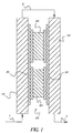
- FIG. 1 is a schematic cross-sectional view of a thermoelectric Peltier heat transfer device of the present invention having two thermoelectric heat transfer modules.
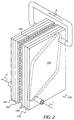
- FIG. 2 is perspective illustration of a thermoelectric Peltier heat transfer device of the present invention.
- FIG. 3 is a schematic cross-sectional view of the device shown in FIG. 2.
- FIGS. 4-6 show various flow channel configurations that can be used in thermoelectric Peltier heat transfer devices of the present invention.
-
- The method of the present invention uses flash pasteurization to rapidly heat a fluid to kill any biogrowth that is present. Yet, because the fluid is at high temperatures for only brief periods of time, the possibility of adverse effects on the fluid are minimized. Since the fluid is heated and cooled in a small, well-insulated device, the efficiency of the method is far greater than if the fluid was heated and cooled in bulk in a large container of some type (such as processing tank or vat). No net evaporation of the fluid occurs since it is treated in a closed environment.
- The heat transfer device of the invention presents several additional advantages. It can be designed so that operators are shielded from the temperature extremes used to treat the fluid, and it is small in size compared to more traditional heat exchangers. It can be readily integrated into various processing systems, such as for food, chemical, photographic, or health processes.
- While aqueous fluids from various industries can be treated in the practice of this invention, it is particularly advantageous for the photographic industry where photographic (or photochemical) processing solutions are treated in-line to control biogrowth in the various processing tanks. Such processing solutions include, but are not limited to, color developing solutions, bleaching solutions, bleach-fixing solutions, fixing solutions, prebleaching, stabilizing solutions, final rinsing solutions and others readily apparent to one skilled in the photographic processing art. The treated processing solutions can be the working strength solutions, concentrates, replenishers, regenerators or make-up water used in replenishment.
- In the first step of the method, the treated fluid is contacted with the hot side of the heat-transfer device for a residence time sufficient for flash pasteurization. This residence time will vary with the particular chemical process in which the treated fluid is used, device design and dimensions, desired operating temperatures, and fluid properties. Generally, most fluids will be in contact with the hot side for at least 5 seconds, and preferably at least 15 seconds. For most photoprocessing solutions, contact with the hot side will generally be for at least 10 seconds, and preferably for at least 20 seconds. The maximum contact time will vary depending upon the particular fluid to be treated.
- Residence time for contact with the cold side of the heat transfer device can be any suitable time needed to cool the treated fluid to the desired temperature. It can be the same or different as the residence time for the hot side.
- Residence time can be varied by using various fluid flow channels or patterns (see for example FIGS. 4-6 as discussed below) or by varying the fluid flow velocity or turbulence using appropriate pumping or other fluid moving means, or obstructions in the fluid flow channels.
- Pasteurization is a known process in various industries, including the food industry to kill biogrowth in milk, and is described for example in more detail in Principles and Practice of Disinfection, Preservation, and Sterilization, (2nd Ed.), Russell, Hugo and Ayliffe (Eds.), Blackwell Scientific Publications, 1992, pp. 494-495, and in the McGraw-Hill Encyclopedia of Science and Technology, (7th Ed.), 1992, page 172. It involves a rapid heating and immediate rapid cooling of the fluid. Its use in the present invention is modified from conventional procedures in that the fluid is not treated in bulk, but in a fluid stream taken out of the process and which can be returned after treatment.
- The temperatures needed for practicing the present invention will also vary with the residence time, but generally, the treated fluid temperature is raised to at least 65°C, and preferably at least 70°C by contact with the hot side of the heat transfer device. The maximum and optimum temperatures can be readily determined by routine experimentation, taking in account the pattern of the fluid flow channel, residence time on the heat-emitting side of the device, fluid volume and other factors. For example, one set of useful conditions would be to treat a fluid to raise its temperature to from about 70 to about 80°C for from about 15 seconds to about 2 minutes.
- Once the fluid is subjected to flash pasteurization, it is directly passed into contact with a cold side of the heat transfer device for immediate and rapid cooling. The time for cooling will vary depending upon the volume of fluid, the temperature it has been heated to, the desired cooled temperature, and the fluid flow pattern. This is achieved by having the hot and cold sides in "direct fluid flow communication" which means that the fluid is not passed through compartment, tanks or otherwise collected or treated between flash pasteurization and cooling. In general, the fluid is passed directly from the hot side of the device to the cold side by plumbing that directly connects the fluid flow channel of one side to the fluid flow channel of the other. Fluid can be moved through the device using suitable pumps, gravity or other means.
- The heat transfer devices used in the practice of the present invention are what are known as Peltier heat transfer devices that are described in various publications, including CRC Handbook of Thermoelectics, Rowe (Ed.), noted above. Several internet publications relating to these devices can be found at http://www.ferrotec-america.com/reference1.html, http://www.ferrotec-america.com/reference2.html, and http://www.ferrotec-america.com/reference3.html. The devices are composed of one or more sets of n- and p-type semiconductor materials through which a temperature differential is generated using current. The sets of semiconductor materials are sometimes known as thermoelectric "modules", and a given heat transfer device can have a plurality (two or more) of such modules if desired. The number of modules is dependent upon the heat pumping capacity of the modules and the overall difference in temperature needed. One commercially available heat transfer module is Model CP 1.4-71-06L sold by Melcor Materials Electronic Products Corporation (Trenton, N.J.). In one embodiment of this invention, eight of these modules were configured to provide four, two-stage (stacked) module devices that were sandwiched between two heat exchanger assemblies.
- The Peltier heat transfer devices and methods of this invention can be further understood by reference to the various drawings.
- In FIG. 1, a fluid to be treated is pumped into (arrow 1) the hot side
fluid flow channel 10 ofdevice 20 that is in contact with thehot side 30 that is in thermoconductive contact with Peltierheat transfer modules fluid flow channel 10 when the polarity of the applied voltage is such that heat is transferred to thehot side 30. Immediately, the fluid is passed (arrow 2) into the cold sidefluid flow channel 50 that is in thermoconductive contact with thecold side 60 ofheat transfer modules device 20. - Although the number of possible flow patterns in the fluid flow channels is numerous, the channels are generally designed to have a flow path that provides adequate heat transfer rate and fluid residence time. The fluid flow channels on each side of the heat transfer device can be the same or different in order to provide the desired residence time on each side. In addition, the fluid flow channels can have any desired internal design that produces turbulence in the treated fluids. For example, turbulence can be created using surface ridges, protrusions, baffles or other obstacles within the fluid flow channel.
- Another embodiment of the invention is illustrated in FIGS. 2 and 3 wherein fluid to be treated (for example a photographic processing solution) is passed into (arrow 1) into fluid flow channel 105 (outlined with dotted lines) of
heat exchanger 110 ofdevice 120 that is in contact with the hot side 130 (thermoconductor) of Peltierheat transfer module 140. The fluid is subjected to flash pasteurization, and immediately passed (arrow 2) throughpiping 141 intofluid flow channel 145 of heat-exchanger 150 that is in thermoconductive contact with thecold side 160 of Peltierheat transfer module 140 wherein the fluid is rapidly cooled. The cooled fluid can then be passed (arrow 3) out of the device. - The fluid flow arrangements into and out of the device shown in FIGS. 1-3 are merely representative of the invention. Various other arrangements for fluid flow would be readily apparent to one skilled in the art. For example, instead of the flow of fluid into and out of the top of the device as shown in FIGS. 2 and 3, the fluid could be introduced into the bottom of the device and withdrawn from the top, or conversely, introduced at the top and withdrawn at the bottom of the device.
- FIGS. 4, 5 and 6 show various fluid flow patterns that can be on either or both sides of the heat transfer device module. In FIG. 4, fluid is introduced by means of
inlet 200, flows acrosssurface ridges exit 260. In FIG. 5, fluid is introduced by means of inlet 270, and passes throughchannel 280 and leaves throughexit 290. In FIG. 6, fluid is introduced by means ofmultiple inlets respective channels respective outlets - The following examples are intended to illustrate the practice of this invention, but are not meant to be limiting in any way.
- About 700 ml of water was recirculated through an embodiment of the heat transfer device of the present invention, similar to that illustrated in FIG. 2, containing 4 two-stage thermoelectric modules (thus, 8 individual Model CP 1.4-71-06L heat transfer modules). Each fluid channel for the hot and cold sides of the device had a volume about 34 ml. The water was recirculated at 20 ml/minute, providing a residence time at the highest temperature of about 1.7 minutes. Complete pasteurization was expected within about 15 seconds at 71°C. In this particular heat transfer device, the hot side was insulated from the environment, but the cold side was not. The thermoelectric modules were operated at 18 volts (DC) and 4.5 amps.
- The following TABLE I shows measured temperatures on both sides of the device, as well as exiting water temperatures, all measured at equilibrium.
Hot side 86.7°C Exiting hot water 78.6°C Cold side 38.0°C Exiting cooled water 43.0°C - This example demonstrates that an aqueous solution can be effectively flash pasteurized in a continuous loop while the solution temperature exiting the device can be maintained within a range suitable for use in photographic processing. The heat exchange efficiency of such devices can be modified and optimized using various channel designs that modify residence times or temperature differentials on either or both hot and cold sides of the heat transfer device.
- In another embodiment of the invention, the hot and cold temperatures were set and maintained by cycling the current on and off at 24 volts (DC), and the current was not specifically controlled. The device used in the experiment was the same as described in Example 1 using the same water flow rate of 20 ml/minute. A small fan was used to aid cooling of the cold side. The equilibrium device and solution temperatures are shown in TABLE II below.
Hot side 85.1°C Exiting hot water 76.7°C Cold side 35.2°C Exiting cooled water 39.9°C - This example demonstrates one method for controlling the solution temperatures by cycling the current on and off to achieve desired temperature differentials.
- This example demonstrates the practice of the present invention using a photographic processing solution, namely, a seasoned photographic stabilizer solution (like commercially available KODAK FLEXICOLOR Stabilizer LF).
- This solution was recirculated through a heat transfer device similar to that illustrated in FIG. 2 using 4, two-stage modules as described in Example 1. The device was operated at 24 volts (DC). In this example, a separate holding tank was used to simulate a photographic processing tank. The temperature of solution in this holding tank was controlled to about 38°C with a conventional immersion circulator heater. A peristaltic pump was used to pump the photographic processing solution from the holding tank to the hot side of the heat transfer device, and back to the holding tank. The fluid flow rate was about 5 ml/min.
- The device and processing solution temperatures were measured at equilibrium and found to be those shown in TABLE III below.
Hot side 91°C Exiting hot water 83°C Cold side 34°C Exiting cooled water 32°C
Claims (10)
- A thermoelectric Peltier heat transfer device having a cold side and a hot side that are in direct fluid flow communication so that the same fluid is treated on both the cold and hot sides of the heat transfer device.
- The heat transfer device of claim 1 comprising two or more thermoelectric modules.
- The heat transfer device of claim 1 or 2 comprising a fluid flow channel in thermal contact with either the hot side or the cold side that is designed to provide turbulence in the fluid being treated in the device.
- The heat transfer device of claim 1, 2 or 3 comprising multiple inlets to the hot and cold sides.
- A method for treating a photographic processing solution in the thermoelectric Peltier heat transfer device of any preceding claim comprising the steps of:A) contacting a photographic processing solution with the hot side of the heat transfer device for a residence time sufficient for flash pasteurization of the photographic processing solution without any volume loss of the flash pasteurized photographic processing solution, andB) directly contacting solely the flash pasteurized photographic processing solution with the cold side to rapidly cool the flash pasteurized photographic processing solution.
- The method of claim 5 wherein the photographic processing solution is a photographic color developing, bleaching, bleach-fixing, prebleaching, stabilizing or final rinsing solution.
- The method of claim 6 wherein the photographic processing solution is contacted with the hot side for at least 10 seconds.
- The method of claim 7 wherein the photographic processing solution is contacted with the heat-emitting source for at least 20 seconds.
- The method of any of claims 5 to 8 wherein the photographic processing fluid is passed through fluid flow channels on both hot and cold sides, and the respective fluid flow channels are different in design and provide different fluid residence times.
- A method for treating a fluid in the thermoelectric Peltier heat transfer device of any preceding claim comprising the steps of:A) contacting a fluid with the hot side of the heat transfer device for a residence time sufficient for flash pasteurization of the fluid without any volume loss of the fluid, andB) directly contacting solely the flash pasteurized fluid with the cold side of the heat transfer device to rapidly cool the flash pasteurized fluid.
Applications Claiming Priority (2)
| Application Number | Priority Date | Filing Date | Title |
|---|---|---|---|
| US268988 | 1999-03-16 | ||
| US09/268,988 US6186681B1 (en) | 1999-03-16 | 1999-03-16 | Method and apparatus for pasteurizing fluids |
Publications (2)
| Publication Number | Publication Date |
|---|---|
| EP1036999A1 true EP1036999A1 (en) | 2000-09-20 |
| EP1036999B1 EP1036999B1 (en) | 2003-08-20 |
Family
ID=23025374
Family Applications (1)
| Application Number | Title | Priority Date | Filing Date |
|---|---|---|---|
| EP00200782A Expired - Lifetime EP1036999B1 (en) | 1999-03-16 | 2000-03-06 | Method and apparatus for pasteurizing fluids |
Country Status (3)
| Country | Link |
|---|---|
| US (1) | US6186681B1 (en) |
| EP (1) | EP1036999B1 (en) |
| DE (1) | DE60004584T2 (en) |
Cited By (1)
| Publication number | Priority date | Publication date | Assignee | Title |
|---|---|---|---|---|
| DE102006004756B4 (en) * | 2005-07-29 | 2015-10-15 | Herbert Wolf | Peltier heat exchanger in modular design |
Families Citing this family (9)
| Publication number | Priority date | Publication date | Assignee | Title |
|---|---|---|---|---|
| US20050279639A1 (en) * | 2004-06-17 | 2005-12-22 | Shrewsburg Timothy J | Coating process and apparatus with improved resistance to bacteria |
| DE102006020503B4 (en) * | 2006-04-22 | 2008-05-08 | Rittal Gmbh & Co. Kg | Arrangement of heat exchanger elements |
| DE102006020502B4 (en) * | 2006-04-22 | 2008-05-08 | Rittal Gmbh & Co. Kg | cooling unit |
| DE102006020499B4 (en) * | 2006-04-22 | 2008-05-08 | Rittal Gmbh & Co. Kg | cooling unit |
| DE102006034487B4 (en) * | 2006-07-20 | 2008-05-08 | Rittal Gmbh & Co. Kg | heat exchangers |
| US8498729B2 (en) | 2008-08-29 | 2013-07-30 | Smp Logic Systems Llc | Manufacturing execution system for use in manufacturing baby formula |
| EP2694888A2 (en) * | 2011-04-05 | 2014-02-12 | Koolkwic Limited | Cooling apparatus |
| DE102017004799A1 (en) * | 2017-05-18 | 2018-11-22 | Gentherm Gmbh | The heat exchange module |
| DE102017011794B4 (en) * | 2017-12-20 | 2024-09-12 | Wolfgang Siegfried Maeding | Peltier heat exchanger |
Citations (3)
| Publication number | Priority date | Publication date | Assignee | Title |
|---|---|---|---|---|
| JPS58219121A (en) * | 1982-06-15 | 1983-12-20 | Meiji Milk Prod Co Ltd | Preparation of nutrimental composition for patient with advanced disease |
| US5027145A (en) * | 1990-08-29 | 1991-06-25 | Eastman Kodak Company | Heat exchanger for film processor |
| US5584183A (en) * | 1994-02-18 | 1996-12-17 | Solid State Cooling Systems | Thermoelectric heat exchanger |
Family Cites Families (6)
| Publication number | Priority date | Publication date | Assignee | Title |
|---|---|---|---|---|
| US3506543A (en) | 1964-07-13 | 1970-04-14 | Whirlpool Co | Urine recovery process by thermoelectric distillation and filtration |
| US4316774A (en) | 1979-07-05 | 1982-02-23 | United Technologies Corporation | Thermoelectric integrated membrane evaporation system |
| JPH0733402Y2 (en) | 1989-03-01 | 1995-07-31 | Connector device | |
| US5353085A (en) | 1991-12-28 | 1994-10-04 | Konica Corporation | Automatic processor for processing silver halide photographic light-sensitive material |
| US5452045A (en) | 1992-10-30 | 1995-09-19 | Konica Corporation | Apparatus for processing a light-sensitive silver halide photographic material |
| DE9303488U1 (en) * | 1993-03-10 | 1994-07-14 | Westronic Steuerungs- und Antriebstechnik GmbH, 59174 Kamen | Device for developing laminated and exposed proofs |
-
1999
- 1999-03-16 US US09/268,988 patent/US6186681B1/en not_active Expired - Lifetime
-
2000
- 2000-03-06 EP EP00200782A patent/EP1036999B1/en not_active Expired - Lifetime
- 2000-03-06 DE DE60004584T patent/DE60004584T2/en not_active Withdrawn - After Issue
Patent Citations (3)
| Publication number | Priority date | Publication date | Assignee | Title |
|---|---|---|---|---|
| JPS58219121A (en) * | 1982-06-15 | 1983-12-20 | Meiji Milk Prod Co Ltd | Preparation of nutrimental composition for patient with advanced disease |
| US5027145A (en) * | 1990-08-29 | 1991-06-25 | Eastman Kodak Company | Heat exchanger for film processor |
| US5584183A (en) * | 1994-02-18 | 1996-12-17 | Solid State Cooling Systems | Thermoelectric heat exchanger |
Non-Patent Citations (1)
| Title |
|---|
| DATABASE WPI Section Ch Week 198405, Derwent World Patents Index; Class B05, AN 1984-027468, XP002901030 * |
Cited By (1)
| Publication number | Priority date | Publication date | Assignee | Title |
|---|---|---|---|---|
| DE102006004756B4 (en) * | 2005-07-29 | 2015-10-15 | Herbert Wolf | Peltier heat exchanger in modular design |
Also Published As
| Publication number | Publication date |
|---|---|
| DE60004584T2 (en) | 2004-07-01 |
| DE60004584D1 (en) | 2003-09-25 |
| US6186681B1 (en) | 2001-02-13 |
| EP1036999B1 (en) | 2003-08-20 |
Similar Documents
| Publication | Publication Date | Title |
|---|---|---|
| EP1036999B1 (en) | Method and apparatus for pasteurizing fluids | |
| TW420829B (en) | Treatment device and method, impurity removing apparatus | |
| US5184471A (en) | Food products chiller and method of using the same | |
| US4333485A (en) | Water-based cleaning system | |
| US6588327B2 (en) | Pasteurizer | |
| CN100510573C (en) | Space-saving food refrigerator | |
| CA2136536A1 (en) | A cooking apparatus | |
| JPH01309636A (en) | Method and apparatus for cooling and sterilizing slaughtered animal in ozonated water | |
| JP2002181490A (en) | Heat exchanger and method of heat exchange | |
| JP3778900B2 (en) | Sterilizer and hydroponics system using the same | |
| DE69112581T2 (en) | DEVICE FOR HEATING AND COOLING FOOD ITEMS. | |
| US4177143A (en) | Elimination of strainer fouling in recirculating cooling water systems | |
| JP2928093B2 (en) | Photosensitive material processing apparatus having modular processing channels | |
| US20090039030A1 (en) | Antimicrobial water treatment system and method | |
| WO1990002707A1 (en) | Water treatment system | |
| EP2974603B1 (en) | A pasteurizer for continuously treating small volumes of liquid foods | |
| JPH01184093A (en) | Heat pump type thermal sterilizer and thermal sterilizing method | |
| WO2005079594A1 (en) | Gas treatment apparatus | |
| JPS6115674A (en) | Freshness keeper for fresh foods | |
| CN115915959A (en) | Apparatus and method for processing food containers | |
| KR20060006023A (en) | Liquid food processing equipment | |
| JP3104886B2 (en) | Heat exchanger | |
| RU175013U1 (en) | DEVICE FOR QUICK DEFROSTING AND HEATING OF FROZEN MATERIAL | |
| EP4218423A1 (en) | Two-step cooking | |
| JPH01199568A (en) | Plate style sterilizing apparatus |
Legal Events
| Date | Code | Title | Description |
|---|---|---|---|
| PUAI | Public reference made under article 153(3) epc to a published international application that has entered the european phase |
Free format text: ORIGINAL CODE: 0009012 |
|
| AK | Designated contracting states |
Kind code of ref document: A1 Designated state(s): DE FR GB |
|
| AX | Request for extension of the european patent |
Free format text: AL;LT;LV;MK;RO;SI |
|
| 17P | Request for examination filed |
Effective date: 20010222 |
|
| AKX | Designation fees paid |
Free format text: DE FR GB |
|
| GRAH | Despatch of communication of intention to grant a patent |
Free format text: ORIGINAL CODE: EPIDOS IGRA |
|
| GRAS | Grant fee paid |
Free format text: ORIGINAL CODE: EPIDOSNIGR3 |
|
| GRAA | (expected) grant |
Free format text: ORIGINAL CODE: 0009210 |
|
| AK | Designated contracting states |
Designated state(s): DE FR GB |
|
| REG | Reference to a national code |
Ref country code: GB Ref legal event code: FG4D |
|
| REF | Corresponds to: |
Ref document number: 60004584 Country of ref document: DE Date of ref document: 20030925 Kind code of ref document: P |
|
| ET | Fr: translation filed | ||
| PLBE | No opposition filed within time limit |
Free format text: ORIGINAL CODE: 0009261 |
|
| STAA | Information on the status of an ep patent application or granted ep patent |
Free format text: STATUS: NO OPPOSITION FILED WITHIN TIME LIMIT |
|
| 26N | No opposition filed |
Effective date: 20040524 |
|
| PGFP | Annual fee paid to national office [announced via postgrant information from national office to epo] |
Ref country code: GB Payment date: 20050207 Year of fee payment: 6 |
|
| PGFP | Annual fee paid to national office [announced via postgrant information from national office to epo] |
Ref country code: FR Payment date: 20050302 Year of fee payment: 6 |
|
| PGFP | Annual fee paid to national office [announced via postgrant information from national office to epo] |
Ref country code: DE Payment date: 20050331 Year of fee payment: 6 |
|
| PG25 | Lapsed in a contracting state [announced via postgrant information from national office to epo] |
Ref country code: DE Free format text: LAPSE BECAUSE OF THE APPLICANT RENOUNCES Effective date: 20060221 |
|
| PG25 | Lapsed in a contracting state [announced via postgrant information from national office to epo] |
Ref country code: GB Free format text: LAPSE BECAUSE OF NON-PAYMENT OF DUE FEES Effective date: 20060306 |
|
| GBPC | Gb: european patent ceased through non-payment of renewal fee |
Effective date: 20060306 |
|
| REG | Reference to a national code |
Ref country code: FR Ref legal event code: ST Effective date: 20061130 |
|
| PG25 | Lapsed in a contracting state [announced via postgrant information from national office to epo] |
Ref country code: FR Free format text: LAPSE BECAUSE OF NON-PAYMENT OF DUE FEES Effective date: 20060331 |