EP1036848A1 - Runner for a shaft furnace - Google Patents
Runner for a shaft furnace Download PDFInfo
- Publication number
- EP1036848A1 EP1036848A1 EP00105167A EP00105167A EP1036848A1 EP 1036848 A1 EP1036848 A1 EP 1036848A1 EP 00105167 A EP00105167 A EP 00105167A EP 00105167 A EP00105167 A EP 00105167A EP 1036848 A1 EP1036848 A1 EP 1036848A1
- Authority
- EP
- European Patent Office
- Prior art keywords
- plate
- tapping
- lining
- shaped cooling
- trough
- Prior art date
- Legal status (The legal status is an assumption and is not a legal conclusion. Google has not performed a legal analysis and makes no representation as to the accuracy of the status listed.)
- Granted
Links
- 238000001816 cooling Methods 0.000 claims abstract description 48
- 238000010079 rubber tapping Methods 0.000 claims abstract description 38
- 239000010949 copper Substances 0.000 claims abstract description 35
- RYGMFSIKBFXOCR-UHFFFAOYSA-N Copper Chemical compound [Cu] RYGMFSIKBFXOCR-UHFFFAOYSA-N 0.000 claims abstract description 28
- 229910052802 copper Inorganic materials 0.000 claims abstract description 28
- 239000002826 coolant Substances 0.000 claims description 15
- 239000011819 refractory material Substances 0.000 claims description 10
- 239000002893 slag Substances 0.000 claims description 7
- 239000000155 melt Substances 0.000 claims description 5
- 229910001338 liquidmetal Inorganic materials 0.000 claims description 3
- 229910000881 Cu alloy Inorganic materials 0.000 claims description 2
- 229910000805 Pig iron Inorganic materials 0.000 claims description 2
- 230000000295 complement effect Effects 0.000 claims description 2
- 230000005484 gravity Effects 0.000 claims description 2
- 238000004519 manufacturing process Methods 0.000 claims description 2
- 239000002184 metal Substances 0.000 claims description 2
- 229910052751 metal Inorganic materials 0.000 claims description 2
- 230000000694 effects Effects 0.000 description 2
- 239000000463 material Substances 0.000 description 2
- XLYOFNOQVPJJNP-UHFFFAOYSA-N water Substances O XLYOFNOQVPJJNP-UHFFFAOYSA-N 0.000 description 2
- 229910001018 Cast iron Inorganic materials 0.000 description 1
- 229910001060 Gray iron Inorganic materials 0.000 description 1
- 229910000831 Steel Inorganic materials 0.000 description 1
- 230000009286 beneficial effect Effects 0.000 description 1
- 230000015572 biosynthetic process Effects 0.000 description 1
- 239000011449 brick Substances 0.000 description 1
- 239000000498 cooling water Substances 0.000 description 1
- 238000005261 decarburization Methods 0.000 description 1
- 238000005553 drilling Methods 0.000 description 1
- 230000002349 favourable effect Effects 0.000 description 1
- 238000009434 installation Methods 0.000 description 1
- 230000003647 oxidation Effects 0.000 description 1
- 238000007254 oxidation reaction Methods 0.000 description 1
- 239000007787 solid Substances 0.000 description 1
- 239000007858 starting material Substances 0.000 description 1
- 239000010959 steel Substances 0.000 description 1
- 238000003466 welding Methods 0.000 description 1
Images
Classifications
-
- F—MECHANICAL ENGINEERING; LIGHTING; HEATING; WEAPONS; BLASTING
- F27—FURNACES; KILNS; OVENS; RETORTS
- F27D—DETAILS OR ACCESSORIES OF FURNACES, KILNS, OVENS, OR RETORTS, IN SO FAR AS THEY ARE OF KINDS OCCURRING IN MORE THAN ONE KIND OF FURNACE
- F27D1/00—Casings; Linings; Walls; Roofs
- F27D1/12—Casings; Linings; Walls; Roofs incorporating cooling arrangements
-
- C—CHEMISTRY; METALLURGY
- C21—METALLURGY OF IRON
- C21B—MANUFACTURE OF IRON OR STEEL
- C21B7/00—Blast furnaces
- C21B7/14—Discharging devices, e.g. for slag
-
- F—MECHANICAL ENGINEERING; LIGHTING; HEATING; WEAPONS; BLASTING
- F27—FURNACES; KILNS; OVENS; RETORTS
- F27D—DETAILS OR ACCESSORIES OF FURNACES, KILNS, OVENS, OR RETORTS, IN SO FAR AS THEY ARE OF KINDS OCCURRING IN MORE THAN ONE KIND OF FURNACE
- F27D3/00—Charging; Discharging; Manipulation of charge
- F27D3/14—Charging or discharging liquid or molten material
- F27D3/145—Runners therefor
Definitions
- the present invention relates to a tapping gutter for a shaft furnace, in particular for a blast furnace for the production of pig iron, consisting of a Trough with a refractory lining that carries the liquid metal or the slag.
- a tapping trough for a shaft furnace that consists of a trough with a refractory
- the liquid metal leading lining is made within the refractory lining hollow cooling elements with connecting pipes for the inflow and outflow of Provide cooling water.
- These cooling elements are in turn limited by plates. Other copper plates run parallel to these plates, but they are not connected stand with the cooling element.
- These cooling elements are around coils of heat-resistant steel, which in a known manner with anchors are fixed in the wear lining of the tapping trough. It is also known to be welded To provide copper profiles as cooling elements for tapping troughs.
- staves As is known, two systems are used for wall cooling in the blast furnace Commitment. These are on the one hand cooling boxes, on the other hand plate-shaped cooling elements, so-called staves. There are cooling plate systems made from copper plates as well Plate cooler made of cast iron. Staves cool the entire blast furnace shell and require little entry. Gray cast iron staves are usually cooling elements, be poured into the cooling pipes.
- Copper staves have been known for blast furnace cooling for more than 15 years.
- Rolled copper slabs were chosen as the starting material.
- the Cooling element was made by drilling the cooling channels, welding thick-walled Copper pipes for the water supply through the blast furnace and suitable mechanical processing of the Stave surface.
- Copper staves are usually 150mm thick and allow for a given thickness of Masonry an increase in volume of the blast furnace of 3 to 5%.
- copper staves are combined with refractory bricks during their installation.
- a known example of copper staves is shown in DE 29 07 511 C2.
- the refractory lining of the tapping gutter has at least one plate-shaped cooling element made of copper or a copper alloy (copper stave) with inside arranged coolant channels is provided. It will use the already known copper cooling plates during cooling of the blast furnace shell, i.e. Copper staves, proposed for cooling troughs. Beneficial Embodiments of the invention are disclosed in the subclaims.
- the optimal cooling effect due to the copper staves increases the service life the refractory material of a tapping channel (or pool channel) increases and the signs of wear reduced. It will increase the durability of the refractory material achieved and thus a saving of refractory material costs. The amount of costly refractory material can also be due to the cooling effect be made smaller. The cooling determines wear Decarburization and oxidation phenomena in the refractory material prevented.
- the copper stave is preferably on its side facing the melt or slag Partly provided with fireproof material.
- the copper stave is preferably on its side facing the melt or slag Partly provided with fireproof material.
- the copper stave is preferably cast or rolled or forged.
- the cooling channels are either through cast pipes formed or poured directly.
- a particularly preferred embodiment of a copper stave is made of one forged or rolled ingot, with the cooling channels vertical running blind holes.
- the tapping channel preferably consists of a trough, this trough consisting of Metal existing outer side walls, one adjoining them on the inside Permanent lining and an inner wear lining made of refractory material.
- the arrangement of the copper staves is basically arbitrary and due to thermal To determine calculations.
- a semi-ring-shaped arrangement is favorable the copper staves around the tapping gutter, either in the area of the wear lining or between wear and permanent feed.
- the copper staves In order to create the coolant flow, the copper staves have connecting pipelines for the coolant supply and discharge. It can be one or more Cooling circuits may be provided; in the smallest unit, each has a plate shape Cooling element a separate circuit. Depending on the selection, the coolant is water, Oil, air or steam.
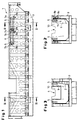
- the tapping channel 1 shown in Figure 1 consists essentially of a metallic Trough 2 (see in particular Figures 2 and 3), which is of a support structure 3 is surrounded.
- a layer of two plate-shaped arranged one behind the other Cooling elements 5 are provided.
- These plate-shaped cooling elements act it is Cu staves made of solid Cu bodies with blind holes Cooling channels 6.
- Each of the Cu staves is triangular on both sides End piece 7a, 7b extended.
- the triangular end pieces 7a, 7b are there formed so that the edges of two end pieces meet diagonally.
- FIG. 2 shows the cross section of the tapping channel according to FIG. 1 in its inlet area.
- the metallic trough 2 which is surrounded by the support structure 3, is with a permanent lining 9 made of refractory material and with an adjoining one Wear lining 10 lined.
- the along the longitudinal axis of the launder arranged Cu staves 5 are arranged approximately at the level of the tapping channel 4. It is because of the triangular end pieces in height to each other staggered pipe socket 8a, 8b for the inflow and outflow of the coolant recognizable.
- the Cu staves point to the tapping channel and thus the Melt or slag facing side horizontally extending grooves 11, fireproof material is worked into the spaces between them.
- FIG. 3 shows the cross section of a second embodiment of a tapping trough shown.
- the height of the cross section corresponds approximately to the cut III-III.
- the Cu staves are over the inlet area of the Tapping gutter also arranged along the long side within the permanent lining (not shown in Figure 1).
- the tapping channel also differs 3 with regard to the formation of the metallic trough 2.
Landscapes
- Engineering & Computer Science (AREA)
- Mechanical Engineering (AREA)
- General Engineering & Computer Science (AREA)
- Chemical & Material Sciences (AREA)
- Manufacturing & Machinery (AREA)
- Materials Engineering (AREA)
- Metallurgy (AREA)
- Organic Chemistry (AREA)
- Blast Furnaces (AREA)
- Furnace Housings, Linings, Walls, And Ceilings (AREA)
Abstract
Description
Die vorliegende Erfindung betrifft eine Abstichrinne für einen Schachtofen, insbesondere für einen Hochofen zur Erzeugung von Roheisen, bestehend aus einem Trog mit einer feuerfesten, das flüssige Metall bzw. die Schlacke führenden Auskleidung.The present invention relates to a tapping gutter for a shaft furnace, in particular for a blast furnace for the production of pig iron, consisting of a Trough with a refractory lining that carries the liquid metal or the slag.
Ebenso wie die Dauer einer Hochofenreise hauptsächlich von der Lebensdauer des Hochofenpanzers bestimmt wird, bestimmen die Verschleißeigenschaften der Auskleidung einer Abstichrinne deren Lebensdauer.Just like the duration of a blast furnace trip mainly on the lifespan of the furnace is determined, determine the wear properties of the Lining a tapping trough its lifespan.
Zur Erhöhung der Lebensdauer einer Abstichrinne ist es bekannt, bei einer Abstichrinne für einen Schachtofen, die aus einem Trog mit einer feuerfesten, das flüssige Metall führenden Auskleidung besteht, innerhalb der feuerfesten Auskleidung hohle Kühlelemente mit Anschlußrohrleitungen für den Zu- und Abfluß von Kühlwasser vorzusehen. Diese Kühlelemente sind ihrerseits von Platten begrenzt. Parallel zu diesen Platten verlaufen weitere Kupferplatten, die aber nicht in Verbindung mit dem Kühlelement stehen. Bei diesen Kühlelementen handelt es sich um Rohrschlangen aus warmfesten Stahl, die in an sich bekannter Weise mit Ankern im Verschleißfutter der Abstichrinne fixiert sind. Es ist weiterhin bekannt, geschweißte Kupferprofile als Kühlelemente für Abstichrinnen vorzusehen. To increase the lifespan of a tapping trough, it is known for a tapping trough for a shaft furnace that consists of a trough with a refractory, the liquid metal leading lining is made within the refractory lining hollow cooling elements with connecting pipes for the inflow and outflow of Provide cooling water. These cooling elements are in turn limited by plates. Other copper plates run parallel to these plates, but they are not connected stand with the cooling element. These cooling elements are around coils of heat-resistant steel, which in a known manner with anchors are fixed in the wear lining of the tapping trough. It is also known to be welded To provide copper profiles as cooling elements for tapping troughs.
Bei der Wandkühlung im Hochofen kommen bekanntermaßen zwei Systeme zum Einsatz. Dies sind zum einen Kühlkästen, zum anderen plattenförmige Kühlelemente, sogenannte Staves. Es gibt Kühlplattensysteme aus Kupferplatten sowie Plattenkühler aus Shäroguß. Staves kühlen flächenhaft den gesamten Hochofenpanzer und erfordern wenig Durchtritte. Grauguß-Staves sind üblicherweise Kühlelemente, in die Kühlrohre eingegossen werden.As is known, two systems are used for wall cooling in the blast furnace Commitment. These are on the one hand cooling boxes, on the other hand plate-shaped cooling elements, so-called staves. There are cooling plate systems made from copper plates as well Plate cooler made of cast iron. Staves cool the entire blast furnace shell and require little entry. Gray cast iron staves are usually cooling elements, be poured into the cooling pipes.
Kupfer-Staves sind seit mehr als 15 Jahren für die Kühlung von Hochöfen bekannt. Als Ausgangsmaterial wurden gewalzte Kupferbrammen gewählt. Das Kühlelement stellte man durch Bohren der Kühlkanäle, Anschweißen von dickwandigen Kupferrohren für die Wasserzuführung durch den Hochofenpanzer und eine geeignete mechanische Bearbeitung der Stave-Oberfläche her. Kupfer-Staves sind üblicherweise 150mm dick und gestatten bei gegebener Dicke des Mauerwerks eine Volumenvergrößerung des Hochofens von 3 bis 5%. Üblicherweise werden Kupfer-Staves bei ihrem Einbau mit Feuerfeststeinen kombiniert. Ein bekanntes Beispiel von Kupfer-Staves zeigt die DE 29 07 511 C2.Copper staves have been known for blast furnace cooling for more than 15 years. Rolled copper slabs were chosen as the starting material. The Cooling element was made by drilling the cooling channels, welding thick-walled Copper pipes for the water supply through the blast furnace and suitable mechanical processing of the Stave surface. Copper staves are usually 150mm thick and allow for a given thickness of Masonry an increase in volume of the blast furnace of 3 to 5%. Usually copper staves are combined with refractory bricks during their installation. A known example of copper staves is shown in DE 29 07 511 C2.
Ausgehend von diesem bekannten Stand der Technik ist es Aufgabe der vorliegenden Erfindung, die Lebensdauer einer Abstichrinne zu erhöhen.Based on this known prior art, it is the object of the present Invention to increase the life of a launder.
Diese Aufgabe wird erfindungsgemäß mittels der Merkmale des Anspruch 1 gelöst. Es wird vorgeschlagen, daß innerhalb der feuerfesten oder angrenzend an die feuerfeste Auskleidung der Abstichrinne mindestens ein plattenförmiges Kühlelement aus Kupfer oder einer Kupferlegierung (Kupfer-Stave) mit in seinem Innern angeordneten Kühlmittelkanälen vorgesehen ist. Es wird die Verwendung der bei der Kühlung des Hochofenpanzers bereits bekannten Kupfer-Kühlplatten, d.h. Kupfer-Staves, für die Kühlung von Abstichrinnen vorgeschlagen. Vorteilhafte Ausgestaltungen der Erfindung sind in den Unteransprüchen offenbart. This object is achieved according to the invention by means of the features of claim 1. It is suggested that within the refractory or adjacent to it the refractory lining of the tapping gutter has at least one plate-shaped cooling element made of copper or a copper alloy (copper stave) with inside arranged coolant channels is provided. It will use the already known copper cooling plates during cooling of the blast furnace shell, i.e. Copper staves, proposed for cooling troughs. Beneficial Embodiments of the invention are disclosed in the subclaims.
Durch diese überraschende und bisher nicht bekannte Verwendung von KupferStaves bei Abstichrinnen, insbesondere die von Hochöfen, ergeben sich folgende Vorteile:This surprising and previously unknown use of copper staves tapping troughs, particularly those of blast furnaces, have the following Benefits:
Durch die optimale Kühlwirkung aufgrund der Kupfer-Staves wird die Standzeit des Feuerfestmaterials einer Abstichrinne (oder Poolrinne) erhöht und die Verschleißerscheinungen vermindert. Es wird eine Haltbarkeitssteigerung des Feuerfestmaterials erreicht und somit eine Einsparung von Feuerfestmaterialkosten. Auch kann aufgrund der Kühlwirkung die Menge an kostenintensivem Feuerfestmaterial verkleinert werden. Durch die Kühlung werden verschleißbestimmende Entkohlungs- und Oxidationserscheinungen im Feuerfestmaterial unterbunden.The optimal cooling effect due to the copper staves increases the service life the refractory material of a tapping channel (or pool channel) increases and the signs of wear reduced. It will increase the durability of the refractory material achieved and thus a saving of refractory material costs. The amount of costly refractory material can also be due to the cooling effect be made smaller. The cooling determines wear Decarburization and oxidation phenomena in the refractory material prevented.
Vorzugsweise ist der Kupfer-Stave auf seiner der Schmelze bzw. Schlacke zugewandten Seite teilweise mit feuerfestem Material versehen. Dies kann beispielsweise dadurch erreicht werden, indem die dem Schmelze- bzw. Schlackenfluß zugekehrte Seite des Kupfer-Staves eingearbeitete horizontal verlaufende Nuten zur Aufnahme von feuerfestem Material aufweist.The copper stave is preferably on its side facing the melt or slag Partly provided with fireproof material. For example can be achieved by the the melt or slag flow facing side of the copper stave integrated horizontal grooves for holding refractory material.
Der Kupfer-Stave ist bevorzugt gegossen oder gewalzt bzw. geschmiedet. Bei einer gegossenen Platte sind die Kühlkanäle entweder durch eingegossene Rohre gebildet oder direkt eingegossen.The copper stave is preferably cast or rolled or forged. At a cast plate, the cooling channels are either through cast pipes formed or poured directly.
Eine besonders bevorzugte Ausführungsform eines Kupfer-Staves ist aus einem geschmiedeten bzw. gewalzten Rohblock gefertigt, wobei die Kühlkanäle vertikal verlaufende Sackbohrungen sind.A particularly preferred embodiment of a copper stave is made of one forged or rolled ingot, with the cooling channels vertical running blind holes.
Die Abstichrinne besteht vorzugsweise aus einem Trog, wobei dieser Trog aus Metall bestehende, äußere Seitenwände, ein sich daran nach innen anschließendes Dauerfutter und ein inneres Verschleißfutter aus feuerfestem Material umfaßt. Die Anordnung der Kupfer-Staves ist grundsätzlich beliebig und aufgrund thermischer Berechnungen zu bestimmen. Günstig ist eine halbringförmige Anordnung der Kupfer-Staves um die Abstichrinne herum, entweder im Bereich des Verschleißfutters oder zwischen Verschleiß- und Dauerfutter.The tapping channel preferably consists of a trough, this trough consisting of Metal existing outer side walls, one adjoining them on the inside Permanent lining and an inner wear lining made of refractory material. The arrangement of the copper staves is basically arbitrary and due to thermal To determine calculations. A semi-ring-shaped arrangement is favorable the copper staves around the tapping gutter, either in the area of the wear lining or between wear and permanent feed.
Zur Schaffung des Kühlmitteldurchflusses weisen die Kupfer-Staves Anschlußrohrleitungen für die Kühlmittelzu- und abfuhr auf. Es können ein oder mehrere Kühlkreise vorgesehen sein; bei der kleinsten Einheit hat jedes plattenförmige Kühlelement einen separaten Kreislauf. Das Kühlmittel ist je nach Auswahl Wasser, Öl, Luft oder Dampf.In order to create the coolant flow, the copper staves have connecting pipelines for the coolant supply and discharge. It can be one or more Cooling circuits may be provided; in the smallest unit, each has a plate shape Cooling element a separate circuit. Depending on the selection, the coolant is water, Oil, air or steam.
Weitere Vorteile und Merkmale der Erfindung werden deutlich anhand der nachfolgenden Beschreibung eines bevorzugten Ausführungsbeispiels unter Bezugnahme auf die beiliegenden Abbildungen. Darin zeigen:
- Figur 1
- die Seitenansicht einer ersten Ausführungsform einer Abstichrinne mit innerhalb des Dauerfutters eingebrachten Cu-Staves;
Figur 2- den Querschnitt II-II der Abstichrinne nach Figur 1;
- Figur 3
- den Querschnitt einer zweiten Ausführungsform einer Abstichrinne.
- Figure 1
- the side view of a first embodiment of a tapping trough with Cu staves inserted within the permanent lining;
- Figure 2
- the cross-section II-II of the tapping channel according to Figure 1;
- Figure 3
- the cross section of a second embodiment of a tapping channel.
Die in Figur 1 gezeigte Abstichrinne 1 besteht im wesentlichen aus einem metallischen
Trog 2 (vgl. insbesondere Figuren 2 und 3), welcher von einer Stützkonstruktion
3 umgeben ist. Zur Kühlung des Einlaufbereichs der Abstichrinne sind
entlang der Längsachse der Abstichrinne 1 etwa in Höhe des Abstichkanals 4 auf
jeder Seite eine Lage von zwei hintereinander angeordneten plattenförmigen
Kühlelementen 5 vorgesehen. Bei diesen plattenförmigen Kühlelementen handelt
es sich um Cu-Staves aus Cu-Massivkörpern mit durch Sackbohrungen eingebrachten
Kühlkanälen 6. Jeder der Cu-Staves ist beidseitig mit einem dreieckförmigen
Endstück 7a, 7b verlängert. Die dreieckförmigen Endstücke 7a, 7b sind dabei
so ausgebildet, daß die Kanten zweier Endstücke diagonal aneinanderstoßen.
In den ungefähren Schwerpunktbereichen der dreieckförmigen Endstücke 7a, 7b
bleibt genug Platz für den Anschluß von Rohrstutzen bzw. Anschlußrohrleitungen
8a, 8b zur Zu- und Abfuhr des Kühlmittels. Hierzu sind die Rohrstutzen bzw. Anschlußrohrleitungen
8a, 8b mit ebenfalls in die Endstücke eingebrachten Sammelleitungen
(nicht gezeigt) versehen, die das Kühlmittel in die - hier vier parallelen
- Kühlmittelkanäle 6 einspeisen bzw. abführen. Aufgrund der komplementär
zueinander ausgebildeten dreieckförmigen Endstücke 7a, 7b wird eine geeignete
Kühlung selbst an den Stoßbereichen zweier Kühlplatten 5 erreicht, weil jeweils
die Fläche mit dem kühlmitteldurchflossenen Anschlußstutzen seine Wirkung zu
der benachbarten Kühlplatte hin ausdehnt.The tapping channel 1 shown in Figure 1 consists essentially of a metallic
Trough 2 (see in particular Figures 2 and 3), which is of a support structure
3 is surrounded. To cool the inlet area of the tapping channel
along the longitudinal axis of the tapping channel 1 approximately at the level of the tapping
Figur 2 zeigt den Querschnitt der Abstichrinne nach Figur 1 in ihrem Einlaufbereich.
Der metallische Trog 2, der von der Stützkonstruktion 3 umgeben ist, ist mit
einem Dauerfutter 9 aus Feuerfestmaterial sowie mit einem sich daran anschließenden
Verschleißfutter 10 ausgekleidet. Die längs der Längsachse der Abstichrinne
angeordneten Cu-Staves 5 sind etwa in Höhe des Abstichkanals 4 angeordnet.
Es sind die wegen der dreieckförmigen Endstücke in der Höhe zueinander
versetzt angeordneten Rohrstutzen 8a, 8b zum Zu- und Abfluß des Kühlmittels
erkennbar. Die Cu-Staves weisen auf der dem Abstichkanal und somit der
Schmelze- bzw. Schlacke zugekehrten Seite horizontal verlaufende Nuten 11 auf,
in deren Zwischenräume feuerfestes Material eingearbeitet ist.FIG. 2 shows the cross section of the tapping channel according to FIG. 1 in its inlet area.
The
Mit der Figur 3 wird der Querschnitt einer zweiten Ausführungsform einer Abstichrinne
dargestellt. Die Höhe des Querschnitts entsprucht ungefähr dem Schnitt
III-III. Bei dieser Ausführungsform sind die Cu-Staves über den Einlaufbereich der
Abstichrinne hinaus entlang deren Längsseite innerhalb des Dauerfutters angeordnet
(in Figur 1 nicht dargestellt). Des weiteren unterscheidet sich die Abstichrinne
nach Figur 3 hinsichtlich der Ausbildung des metallischen Troges 2.3 shows the cross section of a second embodiment of a tapping trough
shown. The height of the cross section corresponds approximately to the cut
III-III. In this embodiment, the Cu staves are over the inlet area of the
Tapping gutter also arranged along the long side within the permanent lining
(not shown in Figure 1). The tapping channel also differs
3 with regard to the formation of the
Claims (11)
dadurch gekennzeichnet,
daß innerhalb der feuerfesten oder angrenzend an die feuerfeste Auskleidung mindestens ein plattenförmiges Kühlelement (5) aus Kupfer oder einer Kupferlegierung (Kupfer-Stave) mit in seinem Innern angeordneten Kühlmittelkanälen (6) vorgesehen ist.Tapping gutter for a shaft furnace, in particular for a blast furnace for the production of pig iron, consisting of a trough with a refractory lining which carries the liquid metal or the slag,
characterized,
that at least one plate-shaped cooling element (5) made of copper or a copper alloy (copper stave) with coolant channels (6) arranged in its interior is provided within the refractory lining or adjacent to the refractory lining.
dadurch gekennzeichnet,
daß das plattenförmige Kühlelement auf der der Schmelze bzw. Schlacke zugewandten Seite zum Teil mit feuerfestem Material versehen ist.Tapping trough according to claim 1,
characterized,
that the plate-shaped cooling element on the side facing the melt or slag is partially provided with refractory material.
dadurch gekennzeichnet,
daß das plattenförmige Kühlelement (6) gegossen oder gewalzt bzw. geschmiedet ist.Tapping gutter according to claims 1 and 2,
characterized,
that the plate-shaped cooling element (6) is cast or rolled or forged.
dadurch gekennzeichnet,
daß bei der gegossenen Platte die Kühlkanäle entweder durch eingegossene Rohre gebildet sind oder direkt eingegossen sind.Tapping gutter according to claims 1 to 3,
characterized,
that in the cast plate, the cooling channels are either formed by cast pipes or are cast directly.
dadurch gekennzeichnet,
daß das plattenförmige Kühlelement aus einem geschmiedeten bzw. gewalzten Rohblock gefertigt ist und die Kühlkanäle vertikal verlaufende Sackbohrungen sind.Tapping gutter according to claims 1 to 4,
characterized,
that the plate-shaped cooling element is made of a forged or rolled ingot and the cooling channels are vertical blind holes.
dadurch gekennzeichnet,
daß die dem Schmelze- bzw. Schlackenfluß zugekehrte Seite des plattenförmigen Kühlelementes eingearbeitete horizontal verlaufende Nuten (11) zur Aufnahme von feuerfestem Material aufweist.Tapping gutter according to claims 1 to 5,
characterized,
that the side of the plate-shaped cooling element facing the melt or slag flow has machined horizontally running grooves (11) for receiving refractory material.
dadurch gekennzeichnet,
daß der Trog (2) aus Metall bestehende, äußere Seitenwände, ein sich daran anschließendes Dauerfutter (9) und ein inneres Verschleißfutter (10) aufweist und wobei die plattenförmigen Kühlelemente halbringförmig zwischen Dauerfutter und Verschleißfutter bzw. innerhalb des Verschleißfutters angeordnet sind.Tapping gutter according to claims 1 to 6,
characterized,
that the trough (2) made of metal, outer side walls, an adjoining permanent lining (9) and an inner wear lining (10) and the plate-shaped cooling elements are arranged in a semi-ring shape between the permanent lining and the wear lining or within the wear lining.
dadurch gekennzeichnet,
daß die plattenförmigen Kühlelemente oder Einheiten aus mehreren plattenförmigen Kühlelementen Anschlußrohrleitungen (8a, 8b) für die Kühlmittelzu- und abfuhr aufweisen.Tapping gutter according to claims 1 to 7,
characterized,
that the plate-shaped cooling elements or units from several plate-shaped cooling elements have connecting pipelines (8a, 8b) for the coolant supply and removal.
dadurch gekennzeichnet,
daß der metallische Trog (2) mit dem Dauerfutter (9) und sich daran anschließenden Verschleißfutter (10) ausgekleidet ist, wobei in das Verschleißfutter (10) der Kanal (4) für die abgestochene Schmelze eingearbeitet ist, und daß eine Mehrzahl von plattenförmigen Kühlelementen (5) mit längs der Abstichrinne verlaufenden Kühlmittelkanälen (6) nebeneinander einlagig in Höhe des Abstichkanals (4) innerhalb des Dauerfutters (9) angeordnet ist.Tapping trough according to one of claims 1 to 6,
characterized,
that the metallic trough (2) is lined with the permanent lining (9) and adjoining wear lining (10), the channel (4) for the tapped melt being incorporated into the wear lining (10), and that a plurality of plate-shaped cooling elements (5) with coolant channels (6) running along the tapping channel and one side by side in the level of the tapping channel (4) within the permanent chuck (9).
dadurch gekennzeichnet,
daß jedes plattenförmige Kühlelement (5) der Kühlelementlage an seinen beiden Enden mit dreieckfömigen Endstücken (7a, 7b) verlängert ist, die jeweils komplementär zueinander ausgebildet sind, so daß zwei benachbarte Kühlplatten mit diagonal verlaufenden Kanten aneinanderstoßen und daß im Schwerpunktbereich der dreieckförmigen Endstücke (7a, 7b) jeweils die Anschlußrohrleitungen (8a, 8b) für die Kühlmittelzu- oder -abfuhr vorgesehen sind, die mit einem Sammelkanal zur Speisung der Kühlmittelkanäle bzw. zur Abfuhr des Kühlmittels verbunden sind.Tapping trough according to claim 9,
characterized,
that each plate-shaped cooling element (5) of the cooling element layer is extended at both ends with triangular end pieces (7a, 7b), which are each complementary to one another, so that two adjacent cooling plates with diagonally running edges meet and that in the center of gravity of the triangular end pieces (7a , 7b) each the connecting pipelines (8a, 8b) are provided for the coolant supply or removal, which are connected to a collecting channel for supplying the coolant channels or for removing the coolant.
Applications Claiming Priority (4)
| Application Number | Priority Date | Filing Date | Title |
|---|---|---|---|
| DE19911639 | 1999-03-16 | ||
| DE19911639 | 1999-03-16 | ||
| DE10009193 | 2000-02-26 | ||
| DE10009193A DE10009193A1 (en) | 1999-03-16 | 2000-02-26 | Rack gutter for a shaft furnace |
Publications (2)
| Publication Number | Publication Date |
|---|---|
| EP1036848A1 true EP1036848A1 (en) | 2000-09-20 |
| EP1036848B1 EP1036848B1 (en) | 2005-01-26 |
Family
ID=26004539
Family Applications (1)
| Application Number | Title | Priority Date | Filing Date |
|---|---|---|---|
| EP00105167A Expired - Lifetime EP1036848B1 (en) | 1999-03-16 | 2000-03-11 | Runner for a shaft furnace |
Country Status (3)
| Country | Link |
|---|---|
| EP (1) | EP1036848B1 (en) |
| AT (1) | ATE287970T1 (en) |
| ES (1) | ES2234467T3 (en) |
Cited By (1)
| Publication number | Priority date | Publication date | Assignee | Title |
|---|---|---|---|---|
| CN102827979A (en) * | 2012-09-25 | 2012-12-19 | 莱芜钢铁集团有限公司 | Blast furnace slag trough and sealing structure thereof |
Citations (5)
| Publication number | Priority date | Publication date | Assignee | Title |
|---|---|---|---|---|
| US4177974A (en) * | 1977-08-17 | 1979-12-11 | Nippon Kokan Kabushiki Kaisha | Molten slag runner for blast-furnace plant |
| DE3101788A1 (en) * | 1980-02-19 | 1982-01-07 | VEB Bandstahlkombinat Hermann Matern, DDR 1220 Eisenhüttenstadt | Spout, preferably a slag spout (launder) for blast furnaces |
| US4382585A (en) * | 1979-02-26 | 1983-05-10 | Kabel-u. Metallwerke Gutehoffnungshutte AG | Cooling plate for furnaces |
| EP0143971A1 (en) * | 1983-10-28 | 1985-06-12 | Betriebsforschungsinstitut VDEh Institut für angewandte Forschung GmbH | Runner for a shaft furnace |
| WO1999036580A1 (en) * | 1998-01-15 | 1999-07-22 | Paul Wurth S.A. | Tapping launder for an iron smelt |
-
2000
- 2000-03-11 ES ES00105167T patent/ES2234467T3/en not_active Expired - Lifetime
- 2000-03-11 EP EP00105167A patent/EP1036848B1/en not_active Expired - Lifetime
- 2000-03-11 AT AT00105167T patent/ATE287970T1/en not_active IP Right Cessation
Patent Citations (5)
| Publication number | Priority date | Publication date | Assignee | Title |
|---|---|---|---|---|
| US4177974A (en) * | 1977-08-17 | 1979-12-11 | Nippon Kokan Kabushiki Kaisha | Molten slag runner for blast-furnace plant |
| US4382585A (en) * | 1979-02-26 | 1983-05-10 | Kabel-u. Metallwerke Gutehoffnungshutte AG | Cooling plate for furnaces |
| DE3101788A1 (en) * | 1980-02-19 | 1982-01-07 | VEB Bandstahlkombinat Hermann Matern, DDR 1220 Eisenhüttenstadt | Spout, preferably a slag spout (launder) for blast furnaces |
| EP0143971A1 (en) * | 1983-10-28 | 1985-06-12 | Betriebsforschungsinstitut VDEh Institut für angewandte Forschung GmbH | Runner for a shaft furnace |
| WO1999036580A1 (en) * | 1998-01-15 | 1999-07-22 | Paul Wurth S.A. | Tapping launder for an iron smelt |
Cited By (1)
| Publication number | Priority date | Publication date | Assignee | Title |
|---|---|---|---|---|
| CN102827979A (en) * | 2012-09-25 | 2012-12-19 | 莱芜钢铁集团有限公司 | Blast furnace slag trough and sealing structure thereof |
Also Published As
| Publication number | Publication date |
|---|---|
| ATE287970T1 (en) | 2005-02-15 |
| EP1036848B1 (en) | 2005-01-26 |
| ES2234467T3 (en) | 2005-07-01 |
Similar Documents
| Publication | Publication Date | Title |
|---|---|---|
| DE2907511C2 (en) | Cooling plate for shaft furnaces, in particular blast furnaces, and method for producing the same | |
| EP0816515B1 (en) | Cooling plate for metallurgical furnaces of the iron and steel industry | |
| DE19503912C2 (en) | Cooling plate for shaft furnaces, especially blast furnaces | |
| DE102006001812A1 (en) | Mold for continuous casting of metal | |
| EP0705906B1 (en) | Cooling plate for shaft furnaces | |
| EP0741190B1 (en) | Cooling plates for shaft furnaces | |
| DE19727008C1 (en) | Cooling plates for shaft furnaces | |
| EP1381817B1 (en) | Cooling element for cooling a metallurgical furnace | |
| DE19751356C2 (en) | Cooling elements for shaft furnaces | |
| EP1036848B1 (en) | Runner for a shaft furnace | |
| DE3153040C2 (en) | Plate coolers for smelting furnaces, in particular blast furnaces | |
| DE10009193A1 (en) | Rack gutter for a shaft furnace | |
| EP1553192B1 (en) | Mounting device for an burner or lance in a melting furnace | |
| DE10024587A1 (en) | Cooling plate | |
| EP1381699B1 (en) | Cooling plate | |
| EP1322790A1 (en) | Cooling element for shaft furnaces | |
| DE19545984B4 (en) | Cooling plate for melting furnaces | |
| DE60014953T2 (en) | Shaft furnace equipped with cooling plates and method for its production | |
| EP1600717A1 (en) | Cooling member, particularly for the walls of the upper part of an electric arc furnace or a shaft furnace | |
| EP2733225B1 (en) | Cooling element assembly | |
| DE19545048C2 (en) | Cooling plates for shaft furnaces | |
| DE2937038A1 (en) | COOLING ELEMENT FOR INDUSTRIAL OVENS | |
| EP1047796B1 (en) | Tapping launder for an iron smelt | |
| AT410717B (en) | COOLING PLATE WITH REINFORCEMENT PART | |
| DE2935394A1 (en) | OVEN PLANT, ESPECIALLY FOR MELTING ORE CONCENTRATE |
Legal Events
| Date | Code | Title | Description |
|---|---|---|---|
| PUAI | Public reference made under article 153(3) epc to a published international application that has entered the european phase |
Free format text: ORIGINAL CODE: 0009012 |
|
| 17P | Request for examination filed |
Effective date: 20000320 |
|
| AK | Designated contracting states |
Kind code of ref document: A1 Designated state(s): AT BE CH CY DE DK ES FI FR GB GR IE IT LI LU MC NL PT SE |
|
| AX | Request for extension of the european patent |
Free format text: AL;LT;LV;MK;RO;SI |
|
| AKX | Designation fees paid |
Free format text: AT BE CH CY DE DK ES FI FR GB GR IE IT LI LU MC NL PT SE |
|
| RAP1 | Party data changed (applicant data changed or rights of an application transferred) |
Owner name: THYSSENKRUPP STAHL AG Owner name: SMS DEMAG AG |
|
| 17Q | First examination report despatched |
Effective date: 20031118 |
|
| GRAP | Despatch of communication of intention to grant a patent |
Free format text: ORIGINAL CODE: EPIDOSNIGR1 |
|
| GRAS | Grant fee paid |
Free format text: ORIGINAL CODE: EPIDOSNIGR3 |
|
| GRAA | (expected) grant |
Free format text: ORIGINAL CODE: 0009210 |
|
| AK | Designated contracting states |
Kind code of ref document: B1 Designated state(s): AT BE CH CY DE DK ES FI FR GB GR IE IT LI LU MC NL PT SE |
|
| PG25 | Lapsed in a contracting state [announced via postgrant information from national office to epo] |
Ref country code: IE Free format text: LAPSE BECAUSE OF FAILURE TO SUBMIT A TRANSLATION OF THE DESCRIPTION OR TO PAY THE FEE WITHIN THE PRESCRIBED TIME-LIMIT Effective date: 20050126 |
|
| REG | Reference to a national code |
Ref country code: GB Ref legal event code: FG4D Free format text: NOT ENGLISH |
|
| REG | Reference to a national code |
Ref country code: CH Ref legal event code: EP |
|
| REG | Reference to a national code |
Ref country code: SE Ref legal event code: TRGR |
|
| REG | Reference to a national code |
Ref country code: IE Ref legal event code: FG4D Free format text: GERMAN |
|
| REF | Corresponds to: |
Ref document number: 50009319 Country of ref document: DE Date of ref document: 20050303 Kind code of ref document: P |
|
| PG25 | Lapsed in a contracting state [announced via postgrant information from national office to epo] |
Ref country code: CY Free format text: LAPSE BECAUSE OF FAILURE TO SUBMIT A TRANSLATION OF THE DESCRIPTION OR TO PAY THE FEE WITHIN THE PRESCRIBED TIME-LIMIT Effective date: 20050311 |
|
| PG25 | Lapsed in a contracting state [announced via postgrant information from national office to epo] |
Ref country code: MC Free format text: LAPSE BECAUSE OF NON-PAYMENT OF DUE FEES Effective date: 20050331 Ref country code: LI Free format text: LAPSE BECAUSE OF NON-PAYMENT OF DUE FEES Effective date: 20050331 Ref country code: CH Free format text: LAPSE BECAUSE OF NON-PAYMENT OF DUE FEES Effective date: 20050331 |
|
| PG25 | Lapsed in a contracting state [announced via postgrant information from national office to epo] |
Ref country code: DK Free format text: LAPSE BECAUSE OF FAILURE TO SUBMIT A TRANSLATION OF THE DESCRIPTION OR TO PAY THE FEE WITHIN THE PRESCRIBED TIME-LIMIT Effective date: 20050426 Ref country code: GR Free format text: LAPSE BECAUSE OF FAILURE TO SUBMIT A TRANSLATION OF THE DESCRIPTION OR TO PAY THE FEE WITHIN THE PRESCRIBED TIME-LIMIT Effective date: 20050426 |
|
| GBT | Gb: translation of ep patent filed (gb section 77(6)(a)/1977) |
Effective date: 20050511 |
|
| REG | Reference to a national code |
Ref country code: ES Ref legal event code: FG2A Ref document number: 2234467 Country of ref document: ES Kind code of ref document: T3 |
|
| REG | Reference to a national code |
Ref country code: IE Ref legal event code: FD4D |
|
| REG | Reference to a national code |
Ref country code: CH Ref legal event code: PL |
|
| PLBE | No opposition filed within time limit |
Free format text: ORIGINAL CODE: 0009261 |
|
| STAA | Information on the status of an ep patent application or granted ep patent |
Free format text: STATUS: NO OPPOSITION FILED WITHIN TIME LIMIT |
|
| RAP2 | Party data changed (patent owner data changed or rights of a patent transferred) |
Owner name: THYSSENKRUPP STAHL AG Owner name: PAUL WURTH S.A. |
|
| ET | Fr: translation filed | ||
| 26N | No opposition filed |
Effective date: 20051027 |
|
| PGFP | Annual fee paid to national office [announced via postgrant information from national office to epo] |
Ref country code: DE Payment date: 20060214 Year of fee payment: 7 |
|
| PGFP | Annual fee paid to national office [announced via postgrant information from national office to epo] |
Ref country code: FR Payment date: 20060215 Year of fee payment: 7 |
|
| PGFP | Annual fee paid to national office [announced via postgrant information from national office to epo] |
Ref country code: BE Payment date: 20060216 Year of fee payment: 7 |
|
| PGFP | Annual fee paid to national office [announced via postgrant information from national office to epo] |
Ref country code: AT Payment date: 20060217 Year of fee payment: 7 Ref country code: NL Payment date: 20060217 Year of fee payment: 7 |
|
| NLT2 | Nl: modifications (of names), taken from the european patent patent bulletin |
Owner name: PAUL WURTH S.A. EN THYSSENKRUPP STAHL AG Effective date: 20051228 |
|
| PGFP | Annual fee paid to national office [announced via postgrant information from national office to epo] |
Ref country code: ES Payment date: 20060327 Year of fee payment: 7 |
|
| PGFP | Annual fee paid to national office [announced via postgrant information from national office to epo] |
Ref country code: SE Payment date: 20060329 Year of fee payment: 7 |
|
| PGFP | Annual fee paid to national office [announced via postgrant information from national office to epo] |
Ref country code: FI Payment date: 20060330 Year of fee payment: 7 |
|
| PGFP | Annual fee paid to national office [announced via postgrant information from national office to epo] |
Ref country code: IT Payment date: 20060331 Year of fee payment: 7 |
|
| PGFP | Annual fee paid to national office [announced via postgrant information from national office to epo] |
Ref country code: LU Payment date: 20060403 Year of fee payment: 7 |
|
| PG25 | Lapsed in a contracting state [announced via postgrant information from national office to epo] |
Ref country code: FI Free format text: LAPSE BECAUSE OF NON-PAYMENT OF DUE FEES Effective date: 20070311 |
|
| PG25 | Lapsed in a contracting state [announced via postgrant information from national office to epo] |
Ref country code: SE Free format text: LAPSE BECAUSE OF NON-PAYMENT OF DUE FEES Effective date: 20070312 |
|
| EUG | Se: european patent has lapsed | ||
| PG25 | Lapsed in a contracting state [announced via postgrant information from national office to epo] |
Ref country code: AT Free format text: LAPSE BECAUSE OF NON-PAYMENT OF DUE FEES Effective date: 20070311 |
|
| GBPC | Gb: european patent ceased through non-payment of renewal fee |
Effective date: 20070311 |
|
| NLV4 | Nl: lapsed or anulled due to non-payment of the annual fee |
Effective date: 20071001 |
|
| BERE | Be: lapsed |
Owner name: *SMS DEMAG A.G. Effective date: 20070331 Owner name: *THYSSENKRUPP STAHL A.G. Effective date: 20070331 |
|
| PG25 | Lapsed in a contracting state [announced via postgrant information from national office to epo] |
Ref country code: BE Free format text: LAPSE BECAUSE OF NON-PAYMENT OF DUE FEES Effective date: 20070331 Ref country code: PT Free format text: LAPSE BECAUSE OF NON-PAYMENT OF DUE FEES Effective date: 20050626 |
|
| REG | Reference to a national code |
Ref country code: FR Ref legal event code: ST Effective date: 20071130 |
|
| PG25 | Lapsed in a contracting state [announced via postgrant information from national office to epo] |
Ref country code: NL Free format text: LAPSE BECAUSE OF NON-PAYMENT OF DUE FEES Effective date: 20071001 Ref country code: DE Free format text: LAPSE BECAUSE OF NON-PAYMENT OF DUE FEES Effective date: 20071002 |
|
| PG25 | Lapsed in a contracting state [announced via postgrant information from national office to epo] |
Ref country code: GB Free format text: LAPSE BECAUSE OF NON-PAYMENT OF DUE FEES Effective date: 20070311 |
|
| REG | Reference to a national code |
Ref country code: ES Ref legal event code: FD2A Effective date: 20070312 |
|
| PG25 | Lapsed in a contracting state [announced via postgrant information from national office to epo] |
Ref country code: FR Free format text: LAPSE BECAUSE OF NON-PAYMENT OF DUE FEES Effective date: 20070402 Ref country code: ES Free format text: LAPSE BECAUSE OF NON-PAYMENT OF DUE FEES Effective date: 20070312 |
|
| PGFP | Annual fee paid to national office [announced via postgrant information from national office to epo] |
Ref country code: GB Payment date: 20060220 Year of fee payment: 7 |
|
| PG25 | Lapsed in a contracting state [announced via postgrant information from national office to epo] |
Ref country code: LU Free format text: LAPSE BECAUSE OF NON-PAYMENT OF DUE FEES Effective date: 20070311 |
|
| PG25 | Lapsed in a contracting state [announced via postgrant information from national office to epo] |
Ref country code: IT Free format text: LAPSE BECAUSE OF NON-PAYMENT OF DUE FEES Effective date: 20070311 |