EP1035692A2 - Soft decision method and system, and receiver - Google Patents
Soft decision method and system, and receiver Download PDFInfo
- Publication number
- EP1035692A2 EP1035692A2 EP00104538A EP00104538A EP1035692A2 EP 1035692 A2 EP1035692 A2 EP 1035692A2 EP 00104538 A EP00104538 A EP 00104538A EP 00104538 A EP00104538 A EP 00104538A EP 1035692 A2 EP1035692 A2 EP 1035692A2
- Authority
- EP
- European Patent Office
- Prior art keywords
- distortion
- decision
- channel
- outputting
- received signal
- Prior art date
- Legal status (The legal status is an assumption and is not a legal conclusion. Google has not performed a legal analysis and makes no representation as to the accuracy of the status listed.)
- Granted
Links
- 238000000034 method Methods 0.000 title claims abstract description 35
- 238000012549 training Methods 0.000 claims abstract description 44
- 238000004891 communication Methods 0.000 claims abstract description 16
- 239000000969 carrier Substances 0.000 claims description 44
- 238000001514 detection method Methods 0.000 claims description 29
- 238000004364 calculation method Methods 0.000 claims description 28
- 238000013139 quantization Methods 0.000 claims description 12
- 238000013215 result calculation Methods 0.000 description 10
- 238000006243 chemical reaction Methods 0.000 description 9
- 238000010586 diagram Methods 0.000 description 8
- 101000824979 Homo sapiens Transcription factor Sp4 Proteins 0.000 description 6
- 102100022446 Transcription factor Sp4 Human genes 0.000 description 6
- 238000010606 normalization Methods 0.000 description 6
- 230000005540 biological transmission Effects 0.000 description 3
- 101100278529 Caenorhabditis elegans drl-1 gene Proteins 0.000 description 2
- 238000012937 correction Methods 0.000 description 2
- 230000009466 transformation Effects 0.000 description 2
- 230000001419 dependent effect Effects 0.000 description 1
- 230000000694 effects Effects 0.000 description 1
- 238000005516 engineering process Methods 0.000 description 1
- 238000013507 mapping Methods 0.000 description 1
- 238000012986 modification Methods 0.000 description 1
- 230000004048 modification Effects 0.000 description 1
Images


Classifications
-
- H—ELECTRICITY
- H04—ELECTRIC COMMUNICATION TECHNIQUE
- H04L—TRANSMISSION OF DIGITAL INFORMATION, e.g. TELEGRAPHIC COMMUNICATION
- H04L25/00—Baseband systems
- H04L25/02—Details ; arrangements for supplying electrical power along data transmission lines
- H04L25/06—DC level restoring means; Bias distortion correction ; Decision circuits providing symbol by symbol detection
- H04L25/067—DC level restoring means; Bias distortion correction ; Decision circuits providing symbol by symbol detection providing soft decisions, i.e. decisions together with an estimate of reliability
Definitions
- the present invention relates to a method and a device of receiving digital signals and a receiver and more particularly, to a method and a device of outputting the demodulation result in soft-decision decoding that enhances the decoding capability of error-correcting codes, which makes it possible to output necessary reliability information with high accuracy, and a receiver using the method or device.
- the soft-decision decoding technique is a technique that estimates the original digital signal from a noise-containing digital signal that has been sent through transmission lines by deciding the level of the noise-containing digital signal as a multi-valued signal (not a two-valued signal) using a plurality of threshold values.
- this technique is one that estimates the two-valued (i.e., "0" and "1"), original information through the multi-valued decoding by deciding the level of the noise-containing digital signal using a plurality of threshold values.
- This technique has an advantage that the error correction rate is better than that of the hard-decision decoding technology that estimates the two-valued, original information through the two-valued decoding by deciding the level of the noise-containing digital signal using a single threshold value.
- the prior-art soft-decision decoding system comprises an input terminal 1000, a demodulation circuit 1001, a level detection circuit 1002, a level normalization circuit 1003, a soft-decision result calculation circuit 1004, a phase-reliability detection circuit 1006, and an output terminal 1005.
- a received signal RS inputted through the input terminal 1000 is applied to the demodulation circuit 1001.
- the circuit 1001 demodulates the signal RS to generate a demodulated signal and then, decodes the demodulated signal using the soft-decision decoding technique;
- the circuit 1001 outputs a decision result, i.e., the demodulated data DD, to the level normalization circuit 1003, the soft-decision result calculation circuit 1004, and the phase-reliability detection circuit 1006.
- the received signal RS is further applied to the level detection circuit 1002 and the phase-reliability detection circuit 1006.
- the level detection circuit 1002 detects the level of the signal RS thus applied and outputs a receiving level signal RSL to the level normalization circuit 1003.
- the level normalization circuit 1003 normalizes the level of the receiving level signal RSL on the basis of the decision result or demodulated data DD, outputting a receiving level reliability data LR.
- the "receiving level reliability" means the reliability relating to the receiving level of the received signal RS.
- the normalization operation of the circuit 1003 is necessitated by the following reason.
- the receiving level reliability is unable to be correctly estimated or evaluated from the receiving level itself. In other words, the receiving level reliability needs to be normalized.
- the phase-reliability detection circuit 1006 detects the phase difference between the received signal RS and the demodulated data or decision result DD outputting the level-based reliability data PR to the soft-decision result calculation circuit 1004.
- the soft-decision result calculation circuit 1004 receives the demodulated data DD the phase-based reliability data PR, and the level-based reliability data LR, outputting a demodulation data DR applicable to the subsequent decoding operation.
- an object of the present invention is to provide a method and a device of outputting a demodulation result in soft-decision decoding that make it possible to output necessary reliability information with high accuracy using a simple circuit configuration.
- Another object of the present invention is to provide a receiver having an enhanced decoding capability of error-correcting codes.
- a method of outputting a demodulation result in soft-decision decoding is provided, which is comprised of the steps of:
- the distortion of the received signal generated in the communication channel is estimated to output the channel distortion data and then, the demodulation result is calculated on the basis of the decision result and the channel distortion data.
- the channel distortion data (instead of the level of the received signal) is used as the level reliability information.
- the level reliability information can be obtained independent of the decision result, which simplifies the circuit configuration.
- the necessary reliability information can be outputted with high accuracy using a simple circuit configuration.
- Another method of outputting a demodulation result in soft-decision decoding is provided, which is comprised of the steps of:
- the channel distortion of the received signal generated in the communication channel is detected using the training signal contained in the received signal and the reference training signal. Also, the distortion-based reliability data is generated from the channel distortion data of the received signal. The received signal is compensated using the channel distortion data to thereby generate the compensated, received signal. Using the compensated, received signal, the decision result is generated. Thus, the channel distortion data (instead of the level of the received signal) of the received signal is used as the level reliability information.
- the level reliability information can be obtained independent of the decision result and therefore, the necessary reliability information can be outputted with high accuracy using a simple circuit configuration.
- a device of outputting a demodulation result in soft-decision decoding which is comprised of:
- the necessary reliability information can be outputted with high accuracy using a simple circuit configuration.
- another device of outputting a demodulation result in soft-decision decoding is provided, which is comprised of:
- the necessary reliability information can be outputted with high accuracy using a simple circuit configuration.
- a receiver which is comprised of:
- the channel-distortion circuit comprises;
- the reliability information calculator circuit comprises;
- the demodulation circuit outputs the n decision results corresponding to the n sub-carriers and n pieces of distance reliability information as reliability information for the n decision results.
- the demodulation circuit comprises;
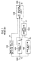
- a device of outputting a demodulation result in soft-decision decoding according to a first embodiment of the invention has the configuration as shown in Fig. 2.
- the device As shown in Fig. 2, the device according to the first embodiment comprises an input terminal 100, a demodulation circuit 101, a soft-decision result calculation circuit 102, a channel distortion detection circuit 103, and an output terminal 104.
- a received signal RS in burst mode is inputted into the device through the input terminal 100.
- the received signal RS is commonly supplied to the demodulation circuit 101 and the channel distortion detection circuit 103.
- the channel distortion detection circuit 103 detects the distortion occurring in the communication channels from the training signal contained in the received signal RS and a reference training signal, outputting a channel distortion data DCC to the demodulation circuit 101. Also, on the basis of the channel distortion data DCC thus obtained, the circuit 103 generates a reliability data DLR and outputs it to the soft-decision result calculation circuit 102.
- the demodulation circuit 101 compensates the received signal RS using the channel distortion data DCC from the circuit 103 and then, generates a decision result DD from the received signal RS thus compensated using the soft-decision technique. Then, the circuit 101 outputs the decision result DD to the soft-decision result calculation circuit 102.
- the soft-decision result calculation circuit 102 receives the decision result DD from the demodulation circuit 101 and the channel distortion data DLR from the channel distortion detection circuit 103, thereby outputting a demodulation result DR toward the output terminal 104 for the subsequent decoding operation.
- Fig. 3 shows an example of the configuration of the channel distortion detection circuit 103 used in the device of Fig. 2.
- the channel distortion detection circuit 103 comprises a correlation calculation circuit 111, a level detection circuit 112, a quantization circuit 113, a training signal point memory 114, and a threshold memory 115.
- An input terminal 110 is connected to the input of the correlation calculation circuit 111.
- An output terminal 116 is connected to the output of the quantization circuit 113.
- Another output terminal 117 is connected to the output of the correlation calculation circuit 111.
- the output terminal 116 is further connected to the input of the soft-decision result operation circuit 102.
- the output terminal 117 is further connected to the input of the demodulation circuit 101.
- the received signal RS is applied to the correlation calculation circuit 111 through the input terminal 110.
- the circuit 111 calculates the correlation between the training signal contained in the received signal RS and a reference training signal that has been stored in the training signal memory 114 in advance, outputting a distortion-compensating coefficient DCC to the level detection circuit 112.
- the distortion-compensating coefficient DCC is sent to the demodulation circuit 101 through the output terminal 117.
- the distortion-compensating coefficient DCC means the distortion of the signal RS encountered in the communication channels.
- the level detection circuit 112 detects the level of the applied distortion-compensating coefficient DCC.
- the correlation or reliability level DRL obtained in the level detection circuit 112 is quantized by the quantization circuit 113 using the threshold values TH stored in the threshold memory 115.
- the circuit 113 outputs the reliability information DLR to the soft-decision result operation circuit 102 through the output terminal 116 on the basis of the channel distortion.
- Fig. 4 shows an example of the configuration of the soft-decision result calculation circuit 102 used in the device of Fig. 2.
- the soft-decision result calculation circuit 102 is formed by a parallel-serial conversion circuit 122.
- An input terminal 120 is connected to the input of the demodulating circuit 101.
- Another input terminal 121 is connected to the output of the channel-distortion detection circuit 103.
- the parallel-serial conversion circuit 122 is supplied with the decision result DD from the demodulation circuit 101 through the input terminal 120 and the reliability data DLR from the channel distortion detection circuit 103 through the input terminal 121. Then, the circuit 122 outputs the demodulation result DR for the subsequent decoding operation to the output terminal 123 or 104.
- the circuit 122 converts the two data DD and DLR supplied in parallel to a serial signal as the demodulation result DR.
- the distortion of the received signal RS generated in the communication channels is detected from the training signal contained in the received signal RS and the reference training signal stored in the training signal point memory 114. Also, the distortion-based reliability data DLR is generated from the channel distortion of the received signal RS in the channel distortion detection circuit 103. The signal RS is compensated using the channel distortion to thereby generate the compensated, received signal. The compensated, received signal is demodulated by the demodulation circuit 101 and soft-decided, generating the decision result DD. Thus, the channel distortion data DCC (instead of the level of the received signal RS) is used as the level reliability information.
- the level reliability information can be obtained independent of the decision result DD and therefore, the necessary reliability information can be outputted with high accuracy using a simple circuit configuration.
- Fig. 5 shows a receiver designed for the Orthogonal Frequency Division Multiplexing (OFDM) system according to a second embodiment of the invention, in which the device of outputting a demodulation result in soft-decision decoding according to the first embodiment is used.
- a received signal RS contains n multiplexed sub-carriers.
- the OFDM type receiver is comprised of an input terminal 200, a timing control circuit 201, a serial-parallel conversion circuit 202, a Fast Fourier Transformation (FFT) circuit 203, n switches 204-1 to 204-n, a channel distortion operation circuit 205, a sub-carrier demodulation circuit 206, a reliability data calculation circuit 207, n parallel-serial conversion circuit 210-1 to 210-n, a multiplexing circuit 211, and an output terminal 212, where n is an integer greater then unity (i.e., n ⁇ 2).
- FFT Fast Fourier Transformation
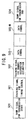
- the received signal RS has a format of packets as shown in Fig. 9.
- This format includes M data symbols 503-1 to 503-M, where M is an integer greater then unity (i.e., M ⁇ 2).
- This format further includes a ramp signal 500 for indicating the transmission start, a training signal 501 for timing control, a training signal 502 for estimating the channel distortion, and a ramp signal 504 for indicating transmission end.
- the receiver of Fig. 5 receives the signal RS with the packet format shown in Fig. 9, the signal RS is supplied to the timing control circuit 201 and the serial-parallel conversion circuit 202.
- the circuit 202 converts the serial data containing sample values forming the respective data symbols 503-1 to 503-M to parallel data signals PS' to the FFT circuit 203.
- the FFT circuit 203 performs the Fourier transformation with respect to the parallel data signals PS' while using the pulse DSP for starting the channel-distortion detection sent from the timing control circuit 201 as a trigger signal.
- the circuit 203 separates the n sub-carriers contained in the parallel data signals PS' and outputs them to the switches 204-1 to 204-n, respectively.
- the timing control circuit 201 has in advance a reference signal whose content corresponds to that of the training signal 501 in the signal RS (see Fig. 9). Then, the circuit 201 compares the content off the training signal 501 in the signal RS with that of the training signal stored previously, generating the correlation data. The circuit 201 defines the timing at which the value of the correlation data exceeds the previously-determined threshold value as the receiving time of the training signal 501.
- the timing control circuit 201 calculates the timing at which the receipt of the training signal 502 for channel-distortion estimation, thereby outputting pulses DSP for starting the channel-distortion detection to the FFT circuit 203 according to the timing thus calculated. Moreover, the circuit 201 calculates the timing at which the first data symbol 503-1 is received, thereby outputting pulses DRP for receiving the data symbols to the switches 204-1 to 204-n according to the timing thus calculated.
- the initial states of the switches 204-1 to 204-n are set in such a way that their input signals are sent to the channel distortion calculation circuit 205.
- the training signal components TS-1 to TS-n for channel distortion estimation of the sub-carriers SC-1 to SC-n are supplied to the circuit 205.
- the pulses for receiving the data symbols are supplied to the switches 204-1 to 204-n, the destination of their input signals are switched to the sub-carrier demodulation circuit 206.
- the data symbol components DS-1 to DS-n of the sub-carriers SC-1 to SC-n are supplied to the circuit 206.
- the channel distortion calculation circuit 205 calculates the channel distortion occurring in the individual sub-carriers SC-1 to SC-n from the training signal components TS-1 to TS-n of the sub-carriers SC-1 to SC-n. Then, the circuit 206 outputs the compensation coefficients (i.e., the sub-carrier compensation coefficients) to the sub-carrier demodulation circuit 206 and the reliability data calculation circuit 207.
- the compensation coefficients i.e., the sub-carrier compensation coefficients
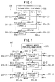
- Fig. 6 shows an example of the configuration of the channel distortion calculation circuit 205 used in the receiver of Fig. 5.
- the channel distortion calculation circuit 205 comprises n input terminals 220- (1) to 220- (n), n division circuits 221- (1) to 221-(n), a training signal point memory 222, and n output terminals 223-(1) to 223-(n).
- the known signal points TSP-1 to TSP-n corresponding respectively to then sub-carriers SC-1 to SC-n have been previously stored in the training signal point memory 222.
- the division circuits 221-(1) to 221-(n) divide the known signal points TSP-1 to TSP-n by the signal points of the training signal components TS-1 to TS-n of the sub-carriers SC-1 to SC-n, respectively, outputting n division results.
- the n division results represent the compensation values for compensating the channel distortion of the respective sub-carriers SC1 to SC-n, which are outputted to the output terminals 223-(1) to 223-(n).
- the sub-carrier demodulation circuit 206 receives the data symbol components DS-1 to DS-n of the sub-carriers SC1 to SC-n from the switches 204-1 to 204-n and the sub-carrier compensation coefficients DCC-1 to DCC-n from the channel distortion calculation circuit 205. Then, the circuit 206 outputs the decision result DD-1 to DD-n for the respective sub-carriers SC-1 to SC-n and the distance-based reliability data SPR-1 to SPR-n to the parallel-serial conversion circuit 210-1 to 210-n, respectively.
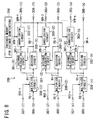
- Fig. 8 shows an example of the configuration of the sub-carrier demodulation circuit 206 used in the receiver of Fig. 5.
- the circuit 206 comprises n input terminals 300-(1) to 300-(n), n input terminals 307-(1) to 307-(n), n decision circuits 302-(1) to 302-(n), n distance calculation circuits 301-(1) to 301-(n), n quantization circuits 303-(1) to 303-(n), a distance threshold memory 304, n multiplier circuits 308-(1) to 308-(n), n output terminals 305-(1) to 305-(n), and n output terminals 306-(1) to 306-(n).
- the components DS-1 to DS-n of the n sub-carriers SC-1 to SC-n are supplied to the multiplier circuits 308-(1) to 308-(n) through the input terminals 300-(1) to 300-(n), respectively.
- the sub-carrier compensation coefficients DCC-1 to DCC-n for the n sub-carriers SC-1 to SC-n are supplied to the multiplier circuits 308-(1) to 308-(n) through the input terminals 307-(1) to 307-(n), respectively.
- the circuits 308-(1) to 308-(n) multiply the components DS-1 to DS-n by the sub-carrier compensation coefficients DCC-1 to DCC-n, generating the output signals DS-1' to DS-n', respectively.
- the channel distortion in the sub-carriers SC-1 to SC-n is compensated.
- the output signals DS-1' to DS-n' of the multiplier circuits 308-(1) to 308- (n) are supplied to the decision circuits 302-(1) to 302-(n) and the distance calculation circuits 301-(1) to 301-(n), respectively.
- the decision circuits 302-(1) to 302-(n) make decision about the applied output signals DS-1' to DS-n' of the multiplier circuits 308-(1) to 308-(n) using the soft-decision technique, thereby outputting the decision data DD-1 to DD-n to the distance calculation circuits 301-(1) to 301-(n) and the output terminals 306-(1) to 306-(n), respectively.
- the distance calculation circuits 301-(1) to 301-(n) perform the mapping operation of the decision data DD-1 to DD-n of the decision circuits 302-(1) to 302-(n) Then, the circuits 301-(1) to 301-(n) calculate the distances SPD-1 to SPD-n between the signal points thus mapped and the output signals DS-1' to DS-n' of the multiplier circuits 308-(1) to 308-(n), thereby supplying the distances SPD-1 to SPD-n to the quantization circuits 303-(1) to 303-(n), respectively.
- the quantization circuits 303-(1) to 303-(n) quantized the distances SPD-1 to SPD-n using the threshold values DTH stored in the threshold memory 304, outputting the distance-based reliability data SPR-1 to SPR-n about the decision results DD of the respective sub-carriers SC-1 to SC-n toward the output terminals 305-(1) to 305-(n), respectively.
- the distance-based reliability data SPR-1 to SPR-n thus outputted are supplied to the parallel-serial conversion circuit 210-1 to 210-n, respectively.
- the reliability data calculation circuit 207 receives the sub-carrier compensation coefficients DCC-1 to DCC-n from the channel distortion calculation circuit 203, outputting the level-based reliability data DLR-1 to DLR-n.
- Fig. 7 shows an example of the configuration of the reliability data calculation circuit 207 used in the receiver of Fig. 5.
- the circuit 207 comprises n input terminals 230-(1) to 230-(n), n level detection circuits 231- (1) to 231-(n), n quantization circuits 232-(1) to 232-(n), a threshold memory 223, and n output terminals 234-(1) to 234-(n).
- the sub-carrier compensation coefficients DCC-1 to DCC-n which are sent from the channel distortion calculation circuit 205, are supplied to the level detection circuits 231-(4) to 231-(n) through the input terminals 230-(1) to 230-(n), respectively.
- the circuits 231-(1) to 231-(n) detect the level of the sub-carrier compensation coefficients DCC-1 to DCC-n, outputting the level data DRL-1 to DRL-n, respectively.
- the level data DRL-1 to DRL-n thus detected are sent to the quantization circuits 232- (1) to 232- (n) and then, quantized according to the threshold values LTH stored in the threshold memory 233, respectively.
- the quantized level data DLR-1 to DLR-n thus obtained are outputted through the output terminals 234-(1) to 234-(n) to the parallel-serial conversion circuits 210-1 to 210-n as the level-based reliability information, respectively.
- the parallel-serial conversion circuits 210-1 to 210-n are supplied with the decision results DD-1 to DD-n, the distance-based reliability information SPR-1 to SPR-n from the sub-carrier demodulation circuit 206, and the level-based reliability information DLR-1 to DLR-n from the reliability data calculation circuit 207. Then, the circuits 210-1 to 210-n convert these data DD-1 to DD-n, SPR-1 to SPR-n, and DLR-1 to DLR-n sent in parallel to n serial data DR-1 to DR-n, respectively. As a result, the demodulation results DR-1 to DR-n for the sub-carriers SC-1 to SC-n, which are applicable to the subsequent decoding operation, are supplied to the multiplexing circuit 211.
- the multiplexing circuit 211 multiplexes the demodulation results DR-1 to DR-n for the sub-carriers SC-1 to SC-n and outputs a multiplexed demodulation result MDR containing the results DR-1 to DR-n to the output terminal 212.
- the device of outputting a demodulation result in soft-decision decoding according to the first embodiment of Fig. 2 is used.
- an enhanced decoding capability of error-correcting codes can be realized.
- the distance-based reliability data SPR-1 to SPR-n are outputted, as shown in Pig. 8.
- the invention is not limited thereto. The invention is applicable to any configuration outputting no distance-based reliability information or data.
Landscapes
- Engineering & Computer Science (AREA)
- Power Engineering (AREA)
- Computer Networks & Wireless Communication (AREA)
- Signal Processing (AREA)
- Digital Transmission Methods That Use Modulated Carrier Waves (AREA)
- Error Detection And Correction (AREA)
Abstract
Description
Claims (9)
- A method of outputting a demodulation result in soft-decision decoding, said method comprising the steps of:(a) demodulating a received signal and deciding said received signal thus demodulated using a soft decision technique, outputting a decision result;(b) estimating a distortion of said received signal generated in a communication channel, outputting a channel distortion data; and(c) calculating a demodulation result on the basis of said decision result and said channel distortion data.
- A method of outputting a demodulation result in soft-decision decoding, said method comprising the steps of:(a) detecting a channel distortion of a received signal generated in a communication channel using a training signal contained in said received signal and a reference training signal, outputting a channel distortion data;(b) generating a distortion-based reliability data from said channel distortion data;(c) compensating said received signal using said channel distortion data, generating a compensated, received signal;(d) demodulating said compensated, received signal and deciding said received signal thus demodulated using a soft decision technique, outputting a decision result; and(e) outputting a demodulation result using said decision result and said distortion-based reliability data.
- A device of outputting a demodulation result in soft-decision decoding, said device comprising:(a) a demodulator means for demodulating a received signal and for deciding said received signal thus demodulated using a soft decision technique, outputting a decision result;(b) a channel distortion estimator means for estimating a distortion of said received signal generated in a communication channel, outputting a channel distortion data to said demodulator; means end(c) a demodulation result calculator means for calculating a demodulation result on the basis of said decision result from said demodulator means and said channel distortion data from said channel distortion estimator means.
- A device of outputting a demodulation result in soft-decision decoding, said device comprising:(a) a channel distortion detector means for detecting a channel distortion of a received signal generated in a communication channel using a training signal contained in said received signal and a reference training signal, outputting a channel distortion data;(b) a distortion-based reliability data generator means for generating a distortion-based reliability data from said channel distortion data;(c) a compensator means for compensating said received signal using said channel distortion data, generating a compensated, received signal;(d) a demodulator means for demodulating said compensated, received signal and deciding said received data thus demodulated using a soft decision technique, outputting a decision result; and(e) a demodulation result output means for outputting a demodulation result using said decision result and said distortion-based reliability data.
- A receiver comprising:(a) a demodulation circuit for outputting n decision results corresponding to n frequency-multiplexed sub-carriers of a received signal by demodulating said n sub-carriers and deciding said n sub-carriers thud demodulated using a soft decision technique, where n is an integer greater than unity;said n decision results being generated by using n channel-distortion coefficients corresponding to said n sub-carriers;(b) a channel-distortion calculation circuit for calculating said n channel-distortion coefficients corresponding to said n sub-carriers;(c) a reliability information calculation circuit for calculating reliability information for said n-decision results corresponding to said n sub-carriers using said n channel-distortion coefficients; and(d) a demodulation result output circuit for outputting a demodulation result using said a decision results corresponding to said n sub-carriers and said reliability information corresponding to said n sub-carriers.
- The receiver according to claim 5 wherein said channel-distortion circuit comprises:a training signal point memory for storing training signal point corresponding to n reference training signal points corresponding to the n sub-carriers; andn division circuits for respectively dividing a training signal points of the a sub-carriers by the n reference training signal points to thereby output the n channel-distortion coefficients.
- The receiver according to claim 5 or 6, wherein said reliability information calculator circuit comprises;n level detection circuits for detecting said level of said n channel-distortion coefficients;a threshold memory for storing threshold values for quantizing the reliability with respect to the level of said n channel-distortion coefficients; andn quantization circuits for quantizing outputs of said n level detection circuits using said threshold values, thereby outputting reliability information corresponding to said n decision results.
- The receiver according to claim 5, 6 or 7, wherein said demodulation circuit outputs said n decision results corresponding to said n sub-carriers and n pieces of distance reliability information as reliability information for said n decision results.
- The receiver according to claim 5, 6, 7 or 8, wherein said demodulation circuit comprises:n multiplier circuits for multiplying said a sub-carriers by said n channel-distortion coefficients;n decision circuits for outputting said n decision results by demodulating said n sub-carriers and outputs of said n multiplier circuits;n distance calculation circuits for calculating a distance between said n decision results and said outputs of said n multiplier circuits in a signal space;a threshold memory for storing threshold values for quantizing said outputs of said n distance calculation circuits; andn quantization circuits for quantizing said outputs of said n distance calculator circuits using said threshold values stored in said threshold memory and said outputs of said a distance calculator circuits, thereby outputting distance reliability information as said reliability information for said n decision results.
Applications Claiming Priority (2)
| Application Number | Priority Date | Filing Date | Title |
|---|---|---|---|
| JP06678499A JP3405258B2 (en) | 1999-03-12 | 1999-03-12 | Soft-decision decoding demodulation result output method and receiver |
| JP6678499 | 1999-03-12 |
Publications (3)
| Publication Number | Publication Date |
|---|---|
| EP1035692A2 true EP1035692A2 (en) | 2000-09-13 |
| EP1035692A3 EP1035692A3 (en) | 2001-06-27 |
| EP1035692B1 EP1035692B1 (en) | 2006-01-18 |
Family
ID=13325846
Family Applications (1)
| Application Number | Title | Priority Date | Filing Date |
|---|---|---|---|
| EP00104538A Expired - Lifetime EP1035692B1 (en) | 1999-03-12 | 2000-03-13 | Soft decision method and system, and receiver |
Country Status (4)
| Country | Link |
|---|---|
| US (1) | US6754291B1 (en) |
| EP (1) | EP1035692B1 (en) |
| JP (1) | JP3405258B2 (en) |
| DE (1) | DE60025546T2 (en) |
Cited By (5)
| Publication number | Priority date | Publication date | Assignee | Title |
|---|---|---|---|---|
| EP0887975A3 (en) * | 1997-06-24 | 2002-02-06 | Sony Corporation | Sequence estimation for multicarrier signals |
| GB2370952A (en) * | 2001-01-05 | 2002-07-10 | British Broadcasting Corp | Improvements in channel state measurement and in discriminating digital values from a received signal, suitable for use with OFDM signals |
| FR2870655A1 (en) * | 2005-05-13 | 2005-11-25 | Samsung Electronics Co Ltd | METHOD FOR DETERMINING CHANNEL STATE AND CHANNEL STATE GENERATOR IN RECEIVER |
| EP1499052A4 (en) * | 2002-04-15 | 2008-07-16 | Matsushita Electric Industrial Co Ltd | RECEIVER AND RECEIVING METHOD THEREOF |
| US7715496B2 (en) | 2004-05-14 | 2010-05-11 | Samsung Electronics Co., Ltd. | Channel state determination method and channel state generator in receiver |
Families Citing this family (7)
| Publication number | Priority date | Publication date | Assignee | Title |
|---|---|---|---|---|
| DE60029488T2 (en) * | 2000-12-28 | 2007-01-04 | Conexant Systems, Inc., Newport Beach | multicarrier demodulator |
| US6980602B1 (en) * | 2001-01-31 | 2005-12-27 | Comsys Communication & Signal Processing Ltd. | Normalization of equalizer soft output for channels with varying noise power |
| JP4539539B2 (en) * | 2005-11-18 | 2010-09-08 | 株式会社デンソー | Soft decision value correction method, receiver, program |
| KR20090097673A (en) * | 2008-03-12 | 2009-09-16 | 삼성전자주식회사 | Device for detecting data stored in memory based on soft decision value |
| GB2467803B (en) * | 2009-04-03 | 2011-01-19 | Cambridge Silicon Radio Ltd | Treating carrier-specific interference |
| US20110004810A1 (en) * | 2009-07-06 | 2011-01-06 | Himax Media Solutions, Inc. | Method and System of Receiving Data with Enhanced Error Correction |
| US9590724B2 (en) * | 2013-05-20 | 2017-03-07 | Futurewei Technologies, Inc. | Cooperative multi-point (CoMP) in a passive optical network (PON) |
Family Cites Families (11)
| Publication number | Priority date | Publication date | Assignee | Title |
|---|---|---|---|---|
| US4742533A (en) * | 1987-01-02 | 1988-05-03 | Motorola, Inc. | Soft decision digital communication apparatus |
| JP2560893B2 (en) | 1990-07-23 | 1996-12-04 | 日本電気株式会社 | Data signal receiver |
| JP2673389B2 (en) * | 1991-03-07 | 1997-11-05 | 松下電器産業株式会社 | Data transmission equipment |
| JP2864988B2 (en) | 1994-06-21 | 1999-03-08 | 日本電気株式会社 | Soft decision signal output type receiver |
| JP2689926B2 (en) * | 1994-12-05 | 1997-12-10 | 日本電気株式会社 | Diversity receiver |
| JP3223755B2 (en) | 1995-05-19 | 2001-10-29 | 三菱電機株式会社 | Soft decision decoding method |
| US5764690A (en) * | 1996-06-04 | 1998-06-09 | Motorola, Inc. | Apparatus for despreading and demodulating a burst CDMA signal |
| JPH10257013A (en) | 1997-03-14 | 1998-09-25 | Toshiba Corp | Receiver |
| JPH1117760A (en) | 1997-06-24 | 1999-01-22 | Sony Corp | Receiving device, transmitting / receiving device, and communication method |
| US6411610B1 (en) * | 1998-11-05 | 2002-06-25 | Nortel Networks Limited | Correlation for synchronizing to long number sequences in communications systems |
| JP3090138B2 (en) | 1999-02-04 | 2000-09-18 | 日本電気株式会社 | Receiving machine |
-
1999
- 1999-03-12 JP JP06678499A patent/JP3405258B2/en not_active Expired - Fee Related
-
2000
- 2000-03-13 EP EP00104538A patent/EP1035692B1/en not_active Expired - Lifetime
- 2000-03-13 DE DE60025546T patent/DE60025546T2/en not_active Expired - Lifetime
- 2000-03-13 US US09/523,844 patent/US6754291B1/en not_active Expired - Lifetime
Cited By (9)
| Publication number | Priority date | Publication date | Assignee | Title |
|---|---|---|---|---|
| EP0887975A3 (en) * | 1997-06-24 | 2002-02-06 | Sony Corporation | Sequence estimation for multicarrier signals |
| GB2370952A (en) * | 2001-01-05 | 2002-07-10 | British Broadcasting Corp | Improvements in channel state measurement and in discriminating digital values from a received signal, suitable for use with OFDM signals |
| GB2370952B (en) * | 2001-01-05 | 2003-04-09 | British Broadcasting Corp | Improvements in channel state measurement and in discriminating digital values from a received signal suitable for use with OFDM signals |
| EP1221793A3 (en) * | 2001-01-05 | 2003-09-10 | British Broadcasting Corporation | Channel estimation and data decisions for multicarrier reception |
| EP1499052A4 (en) * | 2002-04-15 | 2008-07-16 | Matsushita Electric Industrial Co Ltd | RECEIVER AND RECEIVING METHOD THEREOF |
| US7424072B2 (en) | 2002-04-15 | 2008-09-09 | Matsushita Electric Industrial Co., Ltd. | Receiving apparatus and receiving method |
| US7653162B2 (en) | 2002-04-15 | 2010-01-26 | Panasonic Corporation | Receiving apparatus and receiving method |
| US7715496B2 (en) | 2004-05-14 | 2010-05-11 | Samsung Electronics Co., Ltd. | Channel state determination method and channel state generator in receiver |
| FR2870655A1 (en) * | 2005-05-13 | 2005-11-25 | Samsung Electronics Co Ltd | METHOD FOR DETERMINING CHANNEL STATE AND CHANNEL STATE GENERATOR IN RECEIVER |
Also Published As
| Publication number | Publication date |
|---|---|
| JP3405258B2 (en) | 2003-05-12 |
| EP1035692B1 (en) | 2006-01-18 |
| US6754291B1 (en) | 2004-06-22 |
| JP2000270034A (en) | 2000-09-29 |
| EP1035692A3 (en) | 2001-06-27 |
| DE60025546D1 (en) | 2006-04-06 |
| DE60025546T2 (en) | 2006-07-06 |
Similar Documents
| Publication | Publication Date | Title |
|---|---|---|
| JP5307070B2 (en) | Data detection and demodulation for wireless communication systems | |
| US8249116B2 (en) | Methods and systems for timing acquisition robust to channel fading | |
| EP1035692A2 (en) | Soft decision method and system, and receiver | |
| US7436906B2 (en) | Synchronous detector with high accuracy in detecting synchronization and a method therefor | |
| US7822153B2 (en) | Automatic gain control apparatus and method in an orthogonal frequency division multiple access system | |
| US20060165197A1 (en) | Synchronous follow-up device and method | |
| US8170149B2 (en) | OFDM receiver apparatus | |
| US20040059988A1 (en) | Transmission apparatus, reception apparatus, transmission method, and reception method | |
| WO2003071724A1 (en) | Symbol timing correcting circuit, receiver, symbol timing correcting method, and demodulation processing method | |
| EP1608122B1 (en) | Methods and systems for communicating using transmitted symbols associated with multiple time durations | |
| EP1081906A2 (en) | Multicarrier receiver with channel estimation | |
| US20050220175A1 (en) | Circuit for synchronizing symbols of OFDM signal | |
| CN101945076A (en) | Data processing equipment and method | |
| JP2001086092A (en) | OFDM communication device and detection method | |
| US8243858B2 (en) | Receiver and method for receiving | |
| JP2000165341A (en) | OFDM demodulation circuit | |
| KR100789756B1 (en) | Apparatus for determining transmission format using variable frame length, method thereof, and decoding method using same | |
| CN120077619B (en) | Transmitter and receiver for transmitting and receiving symbols on a time-varying channel with doppler spread and method thereof | |
| KR20070014194A (en) | Orthogonal Frequency Division Multiple OPM Packet Detection Unit, Method for Detecting ODF Packet | |
| JP2001069118A (en) | OFDM communication apparatus and propagation path estimation method | |
| EP1531556A1 (en) | Data reception device and data reception method | |
| JP2000228657A (en) | Receiver | |
| CN101394389A (en) | Decoding method and decoding apparatus and receiving apparatus using the same | |
| KR100845204B1 (en) | Ofdm receiver having reduced power consumption and method thereof | |
| JP2002247011A (en) | Receiver for space division multiplex communication |
Legal Events
| Date | Code | Title | Description |
|---|---|---|---|
| PUAI | Public reference made under article 153(3) epc to a published international application that has entered the european phase |
Free format text: ORIGINAL CODE: 0009012 |
|
| AK | Designated contracting states |
Kind code of ref document: A2 Designated state(s): DE NL SE |
|
| AX | Request for extension of the european patent |
Free format text: AL;LT;LV;MK;RO;SI |
|
| PUAL | Search report despatched |
Free format text: ORIGINAL CODE: 0009013 |
|
| AK | Designated contracting states |
Kind code of ref document: A3 Designated state(s): AT BE CH CY DE DK ES FI FR GB GR IE IT LI LU MC NL PT SE |
|
| AX | Request for extension of the european patent |
Free format text: AL;LT;LV;MK;RO;SI |
|
| RIC1 | Information provided on ipc code assigned before grant |
Free format text: 7H 04L 25/06 A, 7H 04L 25/02 B, 7H 04L 25/03 B |
|
| 17P | Request for examination filed |
Effective date: 20010516 |
|
| 17Q | First examination report despatched |
Effective date: 20011109 |
|
| AKX | Designation fees paid |
Free format text: DE NL SE |
|
| GRAP | Despatch of communication of intention to grant a patent |
Free format text: ORIGINAL CODE: EPIDOSNIGR1 |
|
| GRAS | Grant fee paid |
Free format text: ORIGINAL CODE: EPIDOSNIGR3 |
|
| GRAA | (expected) grant |
Free format text: ORIGINAL CODE: 0009210 |
|
| AK | Designated contracting states |
Kind code of ref document: B1 Designated state(s): DE NL SE |
|
| PG25 | Lapsed in a contracting state [announced via postgrant information from national office to epo] |
Ref country code: NL Free format text: LAPSE BECAUSE OF FAILURE TO SUBMIT A TRANSLATION OF THE DESCRIPTION OR TO PAY THE FEE WITHIN THE PRESCRIBED TIME-LIMIT Effective date: 20060118 |
|
| REF | Corresponds to: |
Ref document number: 60025546 Country of ref document: DE Date of ref document: 20060406 Kind code of ref document: P |
|
| PG25 | Lapsed in a contracting state [announced via postgrant information from national office to epo] |
Ref country code: SE Free format text: LAPSE BECAUSE OF FAILURE TO SUBMIT A TRANSLATION OF THE DESCRIPTION OR TO PAY THE FEE WITHIN THE PRESCRIBED TIME-LIMIT Effective date: 20060418 |
|
| NLV1 | Nl: lapsed or annulled due to failure to fulfill the requirements of art. 29p and 29m of the patents act | ||
| PLBE | No opposition filed within time limit |
Free format text: ORIGINAL CODE: 0009261 |
|
| STAA | Information on the status of an ep patent application or granted ep patent |
Free format text: STATUS: NO OPPOSITION FILED WITHIN TIME LIMIT |
|
| 26N | No opposition filed |
Effective date: 20061019 |
|
| PGFP | Annual fee paid to national office [announced via postgrant information from national office to epo] |
Ref country code: DE Payment date: 20160308 Year of fee payment: 17 |
|
| REG | Reference to a national code |
Ref country code: DE Ref legal event code: R119 Ref document number: 60025546 Country of ref document: DE |
|
| PG25 | Lapsed in a contracting state [announced via postgrant information from national office to epo] |
Ref country code: DE Free format text: LAPSE BECAUSE OF NON-PAYMENT OF DUE FEES Effective date: 20171003 |