EP1035596A2 - Super magnetostrictive actuator - Google Patents
Super magnetostrictive actuator Download PDFInfo
- Publication number
- EP1035596A2 EP1035596A2 EP00103277A EP00103277A EP1035596A2 EP 1035596 A2 EP1035596 A2 EP 1035596A2 EP 00103277 A EP00103277 A EP 00103277A EP 00103277 A EP00103277 A EP 00103277A EP 1035596 A2 EP1035596 A2 EP 1035596A2
- Authority
- EP
- European Patent Office
- Prior art keywords
- super magnetostrictive
- super
- magnetostrictive
- magnetic field
- magnetostrictive material
- Prior art date
- Legal status (The legal status is an assumption and is not a legal conclusion. Google has not performed a legal analysis and makes no representation as to the accuracy of the status listed.)
- Granted
Links
Images


Classifications
-
- H—ELECTRICITY
- H10—SEMICONDUCTOR DEVICES; ELECTRIC SOLID-STATE DEVICES NOT OTHERWISE PROVIDED FOR
- H10N—ELECTRIC SOLID-STATE DEVICES NOT OTHERWISE PROVIDED FOR
- H10N35/00—Magnetostrictive devices
Definitions
- the present invention relates to a super magnetostrictive actuator formed by combining at least two super magnetostrictive materials which extend and shrink to the longitudinal direction thereof due to the action of the magnetic field generated by a magnetic field generation means.
- rare earth metal monocrystal such as Tb (terbium), Dy (dysprosium) or the like known as super magnetostrictive material generates enormous magnetostriction which is about several hundred times as that generated by general magnetostrictive material such as Ni, Co or the like. Since TbFe 2 or DyFe 2 which is a binary alloy of Tb and Fe or Dy and Fe is able to generate enormous magnetostriction in the room temperature, such a binary alloy is used as a source for driving an actuator. However, enormous magnetostriction generated by such super magnetostrictive materials only exceeds the displacement of about 0.1% at most.
- Such a super magnetostrictive actuator for securing a required output displacement by combining a plurality of super magnetostrictive materials in this manner is known as disclosed in Japanese Patent Unexamined Publication NO. Hei.4-168984.
- the aforesaid conventional super magnetostrictive actuator is arranged in a manner that a plurality of super magnetostrictive materials formed in a column shape are disposed along the inner periphery of a coil formed in a cylindrical shape, and the end portions of the adjacent super magnetostrictive materials are coupled to each other by a link which is supported at its center portion by a fulcrum. According to the actuator thus arranged, an amount of extension and shrinkage of each of the super magnetostrictive materials is transmitted to the adjacent super magnetostrictive material through the link mechanism thereby to generate a required output displacement between the super magnetostrictive materials positioned at both ends.
- the number of the parts such as the link member and the fulcrum thereof etc. increases and the number of assembling processes thereof also increases.
- the cost of the actuator increases, and further the actuator may be prevented from moving smoothly since the magnitude of friction and the degree of wobble at a movable portion and a sliding portion increase.
- the present invention has been made in view of the aforesaid conventional circumstances, and an object of the present invention is to provide a super magnetostrictive actuator which can obtain sufficient output displacement and operate smoothly with a simple and small-sized configuration having small number of parts.
- a super magnetostrictive actuator formed by combining at least first and second super magnetostrictive materials which expand and shrink to a longitudinal direction thereof due to action of magnetic field generated by magnetic field generating means.
- the second magnetostrictive material of tubular shape is disposed coaxially so as to surround outer side of the first magnetostrictive material along radial direction thereof, and a coupling member of tubular shape disposed coaxially between the first and second super magnetostrictive materials is coupled at its both end portions to one end portion of the first magnetostrictive material and one end portion of the second magnetostrictive material, respectively.
- both the first and second super magnetostrictive materials extend and shrink to the axial direction and so the deviation at the one end portion of the first magnetostrictive material is transmitted to the one end portion of the second magnetostrictive material through the coupling member.
- the deviation corresponding to the sum of amounts of extension/shrinkage of the first and second super magnetostrictive materials can be generated between the other end portion of the first magnetostrictive material and the other end portion of the second magnetostrictive material.
- the coupling member of tubular shape is disposed coaxially so as to surround h the outer side of the first magnetostrictive material along the radial direction thereof and the second magnetostrictive material of tubular shape is disposed coaxially so as to surround the outer side of the coupling member along the radial direction thereof, not only the super magnetostrictive actuator can be configured in a small size but also the extension/shrinkage of the first and second super magnetostrictive materials can be effectively transmitted without causing offset load of the first and second super magnetostrictive materials.
- the coupling member does not has a fulcrum nor a sliding portion and is merely coupled at its both end portions to the first and second super magnetostrictive materials, respectively, the number of the parts can be reduced thereby to realize a simple configuration and so the actuator is advantageous in the economical efficiency, endurance and assembling efficiency.
- the magnetic field generating means may be formed by a coil disposed coaxially so as to surround outer periphery of the second magnetostrictive material.
- the output deviation of the super magnetostrictive actuator can be easily controlled by merely changing the pulse width or the magnitude of the current supplied to the coil. Further, since all the first and second super magnetostrictive materials, the coupling member and the coil are disposed coaxially, the super magnetostrictive actuator can be further configured in a smaller size.
- a fuel injection valve I used in a direct injection engine for natural gas includes a housing 11 of substantially cylindrical shape.
- a nozzle 12 and a cap 13 are fixed to the front end portion and the rear end portion of the housing 11, respectively.
- the super magnetostrictive actuator A received in the rear portion of the housing 11 includes, so as to drive the fuel injection valve I, a coil 14 serving as a magnetic field generating means, a first magnetostrictive material 15, a second magnetostrictive material 16 and a coupling member 17.
- the front end of the coil 14 which is formed in a cylindrical shape and fits in the inner peripheral surface of the housing 11 engages with the step portion 11 1 of the housing 11 through a front guide member 18 having a guide hole 18 1 .
- the rear end of the coil 14 is engaged with the front surface of the cap 13 through a rear guide member 19 having a guide hole 19 1 and a stopper surface 19 2 .
- the first magnetostrictive material 15 is configured by a super magnetostrictive material main body 15 1 formed in a column shape, and a front end member 15 2 and a rear end member 15 3 fixed to the front end and the rear end of the super magnetostrictive material main body 15 1 , respectively.
- a step portion 15 4 is formed at the outer peripheral surface of the rear end member 15 3 .
- the second magnetostrictive material 16 is configured by a super magnetostrictive material main body 16 1 formed in a cylindrical shape, and a front end member 16 2 and a rear end member 16 3 fixed to the front end and the rear end of the super magnetostrictive material main body 16 1 , respectively.
- a step portion 16 4 is formed at the inner peripheral surface of the front end member 16 2 .
- the coupling member 17 made of non-magnetic material and formed in substantially cylindrical shape has a step portion 17 1 at the outer peripheral surface of the front end side thereof and a step portion 17 2 at the inner peripheral surface of the rear end side thereof.
- the second magnetostrictive material 16 is disposed at the inner side of the coil 14 which is fitted into and supported by the housing 11.
- the coupling member 17 is disposed at the inner side of the second super magnetostrictive material 16.
- the first magnetostrictive material 15 is disposed at the inner side of the coupling member 17. In this state, the housing 11, the coil 14, the second magnetostrictive material 16, the coupling member 17 and the first magnetostrictive material 15 are aligned concentrically with respect to the axial line L of the fuel injection valve I.
- the rear end member 16 3 of the second magnetostrictive material 16 abuts against the stopper surface 19 2 of the rear guide member 19 and positioned thereat.
- the front end member 16 2 slidably fits into the inner peripheral surface of the guide hole 18 1 of the front guide member 18.
- the step portion 16 4 of the front end member 16 2 of the second magnetostrictive material 16 engages with the step portion 17 1 of the front side of the coupling member 17.
- the step portion 17 2 of the rear side of the coupling member 17 engages with the step portion 15 4 of the rear end member 15 3 of the first magnetostrictive material 15.
- the rear end member 15 3 of the first magnetostrictive material 15 slidably fits into the guide hole 19 1 of the rear guide member 19.
- the super magnetostrictive material main body 15 1 of the first magnetostrictive material 15 and the super magnetostrictive material main body 16 1 of the second magnetostrictive material 16 are formed by Terfenol-D (trade name), for example.
- the Terfenol-D is an alloy formed by combining TbFe 2 and DyFe 2 .
- the alloy comprises from 27% to 30% of TbFe 2 , and 70% to 73% of DyFe 2 , and the content of Fe in the alloy is from 19% to 20%.
- the Terfenol-D has such a property of the positive magnetostriction (extend with respect to the direction of the magnetic field) and the magnetic anisotropic constant is approximately 0.
- a piston 20 serving as an output member is slidably fitted into a cylinder 11 2 formed at the inner periphery of the front portion of the housing 11.
- a piston rod 20 1 extending backward from the piston 20 abuts against the front end member 15 2 of the first magnetostrictive material 15.
- the front end of a preload spring 21 received within the cylinder 11 2 engages with the rear end of the nozzle 12 through a collar 22 and a washer 23 and the rear end of the preload spring 21 retains with the front surface of the piston 20.
- the piston 20 is biased backward due to the elastic force of the preload spring 21 applied thereto.
- a valve seat 24 and a valve element support member 25 are received within the nozzle 12 having a nozzle hole 12 1 at the tip end thereof.
- a nut 26 having screws formed at the outer peripheral surface thereof is screwed around the inner peripheral surface of the nozzle 12, so as to fix the valve seat 24 and the valve element support member 25.
- the valve element support member 25 has a guide hole 25 1 which penetrates at the center portion thereof along the axial direction therethrough and four ribs 25 2 which are formed with angular interval of 90 degrees and extend radially to the radial direction. The outer ends of the ribs 25 2 are abutted against the inner peripheral surface of the nozzle 12, so that the valve element support member 25 is positioned to the radial direction.
- a valve element 27 has a head portion 27 1 and a shaft portion 27 2 .
- the head portion 27 1 is capable of being seated on the front surface of the valve seat 24 and the shaft portion 27 2 is slidably supported by the guide hole 25 1 of the valve element support member 25.
- a spring seat 28 is provided at the rear end of the shaft portion 27 2 of the valve element 27.
- a valve spring 29 is supported between the front surface of the spring seat 28 and the valve element support member 25 in a compressed state. The head portion 27 1 of the valve element 27 is biased backward by the valve spring 29 and then seated on the valve seat 24.
- a shim 30 is attached between the rear end of the valve spring 29 and the spring seat 28. An amount of the preload of the valve spring 29 can be adjusted by changing the thickness of the shim 30.
- a fuel supply hole 11 3 is formed at the front portion of the housing 11.
- the highly-pressurized fuel supplied into the cylinder 11 2 from the fuel supply hole 11 3 passes among the four ribs 25 2 and further passes a clearance between the valve seat 24 and the head portion 27 1 of the valve element 27 and then injected into the cylinder of the engine from the nozzle hole 12 1 .
- the compressed preload to the axial direction acts on the first magnetostrictive material 15 whose front end member 15 2 is pressed by the piston rod 20 1 .
- the compressed preload acting on the first magnetostrictive material 15 is transmitted from the step portion 15 4 of the rear end member 15 3 to the step portion 17 2 of the rear side of the coupling member 17 thereby to bias the coupling member 17 backward.
- the biasing force for biasing the coupling member 17 backward is transmitted from the step portion 17 1 of the front side of the coupling member 17 to the step portion 16 4 of the front end member 16 2 of the second magnetostrictive material 16.
- the compressed preload to the axial direction acts on the second magnetostrictive material 16 whose rear end member 16 3 is retained by the rear guide member 19.
- Each of the first magnetostrictive material 15 and the second magnetostrictive material 16 being applied with the compressed preload to the axial direction shrinks to the axial direction in accordance with the magnitude of the compressed preload.
- valve element 27 When the coil 14 is not supplied with current, the valve element 27 is biased backward by the valve spring 29 and hence the head portion 27 1 of the valve element 27 is seated on the valve seat 24.
- a clearance ⁇ (see Fig. 2) with a preset size is formed between the front surface of the piston 20 and the rear end of the shaft portion 27 2 of the valve element 27 so that the head portion 27 1 of the valve element 27 is not interfered from being seated on the valve seat 24.
- the first magnetostrictive material 15 and the second magnetostrictive material 16 extend against the compressed preload in accordance with the magnitude of the magnetic field generated by the coil 14.
- the front end member 16 2 moves forward by the extension of the super magnetostrictive material main body 16 1 thereby to move forward the coupling member 17 whose step portion 17 1 of the front side of the coupling member 17 is retained by the step portion 16 4 of the front end member 16 2 .
- the displacement force for moving the coupling member 17 forward is transmitted from the step portion 17 2 of the rear side of the coupling member 17 to the step portion 15 4 of the rear end member 15 3 of the first magnetostrictive material 15.
- the rear end member 15 3 of the first magnetostrictive material 15 moves forward by the length corresponding to the extended length of the second magnetostrictive material 16.
- the front end member 15 2 of the first magnetostrictive material 15 moves forward with respect to the rear end member 15 3 .
- the piston 20 moves forward by the length corresponding to the sum of the extended length of the first magnetostrictive material 15 and that of the second magnetostrictive material 16.
- the clearance ⁇ between the front surface of the piston 20 and the rear end of the shaft portion 27 2 of the valve element 27 becomes shorter, and so the valve element 27 pushed by the piston 20 moves forward against the elastic force of the valve spring 29, whereby the head portion 27 1 of the valve element 27 separates from the valve seat 24.
- the highly-pressurized fuel having been supplied into the cylinder 11 2 from the fuel supply hole 11 3 passes the clearance between the valve seat 24 and the head portion 27 1 of the valve element 27 and then is injected from the nozzle hole 12 1 .
- an amount of fuel injection can be controlled arbitrarily in a manner that the current supplied to the coil 14 is subjected to the pulse width control thereby to change the opened/closed periods of the clearance between the valve seat 24 and the head portion 27 1 of the valve element 27, or in a manner that the magnitude of the current supplied to the coil 14 is controlled thereby to change the size of the clearance between the valve seat 24 and the head portion 27 1 of the valve element 27.
- the super magnetostrictive actuator A can be formed in a compact size. Further, since all the weight of the first magnetostrictive material 15, the coupling member 17 and the second magnetostrictive material 16 acts on the axial line L, asymmetrical deformation around the axial line L of the first magnetostricitive material 15, the coupling member 17 and the second magnetostrictive material 16 can be prevented and the weight is efficiently transmitted, so that the smoothing operation of the super magnetostrictive actuator A can be secured.
- the coupling member 17 does not have a fulcrum nor a sliding portion, the configuration thereof is quite simple. Accordingly, it becomes possible to reduce the number of the parts and the number of the assembling processes, and further the durability of the actuator can be improved and the occurring rate of failure thereof can be reduced. Furthermore, since the coil 14 is employed as the magnetic field generating means, the output displacement of the super magnetostrictive actuator A can be easily and accurately controlled by merely changing the pulse width or the magnitude of the current supplied thereto.
- the elastic force of the valve spring 29 in addition to the elastic force of the preload spring 21 simultaneously acts on the first magnetostrictive material 15 and the second magnetostrictive material 16
- the sum of the elastic force of both the preload spring 21 and the valve spring 29 influences on the dynamic characteristic of the super magnetostrictive actuator A.
- a method of adjusting the sum of the elastic force there are considered a first method of adjusting both the elastic force of the preload spring 21 and the elastic force of the valve spring 29, a second method of adjusting only the elastic force of the preload spring 21, and a third method of adjusting only the elastic force of the valve spring 29.
- the first and second methods including the changing of the elastic force of the preload spring 21 are not preferable.
- the elastic force of the preload spring 21 is preset at a value capable of obtaining the desired clearance ⁇ and the elastic force of the valve spring 29 is adjusted by changing the thickness of the shim 30 in this state
- the sum of the elastic force of the preload spring 21 and the valve spring 29 can be adjusted to a magnitude capable of obtaining a target dynamic characteristic.
- the size of the clearance ⁇ does not change irrespective of the adjustment of the elastic force of the valve spring 29.
- the dynamic characteristic of the super magnetostrictive actuator A can be adjusted easily without changing the size of the clearance ⁇ by such a simple procedure of merely changing the thickness of the shim 30 supporting the one end of the valve spring 29.
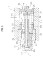
- the shim 30 is disposed between the rear end of the valve spring 29 and the front surface of the piston 20, the shim 30 may be disposed between the front end of the valve spring 29 and the rear surface of the valve element support member 25 like the second embodiment shown in Fig. 5. In such a modification, the same function and effects like the first embodiment can be obtained.
- the present invention may be applied to a super magnetostrictive actuator for other arbitrary usage.
- a super magnetostrictive actuator includes: a magnetic field generating unit, at least first and second super magnetostrictive members extensible to a longitudinal direction thereof due to action of magnetic field generated by the magnetic field generating unit, and a coupling member having a cylindrical shape and disposed coaxially between the first and second super magnetostrictive members.
- the second super mangetostrictive member has a cylindrical shape and is coaxially disposed to surround around the outside of the first super magnetostrictive member in a radial direction thereof. Both end portions of the coupling member are coupled to one end portion of the first super magnetostrictive member and one end portion of the second super magnetostrictive member, respectively.
Landscapes
- Fuel-Injection Apparatus (AREA)
- General Electrical Machinery Utilizing Piezoelectricity, Electrostriction Or Magnetostriction (AREA)
Abstract
Description
Claims (6)
- A super magnetostrictive actuator, comprising:a magnetic field generating means;at least first and second super magnetostrictive members extensible to a longitudinal direction thereof due to action of magnetic field generated by said magnetic field generating means, said second super mangetostrictive member having a cylindrical shape and being coaxially disposed to surround around the outside of said first super magnetostrictive member in a radial direction thereof; anda coupling member having a cylindrical shape and disposed coaxially between said first and second super magnetostrictive members,
wherein both end portions of said coupling member are coupled to one end portion of said first super magnetostrictive member and one end portion of said second super magnetostrictive member, respectively. - A super magnetostrictive actuator according to claim 1, wherein said magnetic field generating means is disposed coaxially so as to surround an outer periphery of said second super magnetostrictive member.
- A super magnetostrictive actuator according to claim 1, wherein said magnetic field generating means is formed by a coil disposed coaxially so as to surround an outer periphery of said second super magnetostrictive member.
- A super magnetostrictive actuator according to claim 1, wherein said first and second super magnetostrictive member is formed of an alloy including rare earth metal monocrystal.
- A super magnetostrictive actuator according to claim 1, wherein said coupling member is formed of non-magnetic material.
- A super magnetostrictive actuator according to claim 1, further comprising:a housing,
wherein one of the other end portions of said first and second super mangetostrictive members is positioned to said housing, and the other of the other end portions of said first and second super magnetostrictive members is movable with respect to said housing in said longitudinal direction.
Applications Claiming Priority (2)
| Application Number | Priority Date | Filing Date | Title |
|---|---|---|---|
| JP5867799 | 1999-03-05 | ||
| JP11058677A JP2000262076A (en) | 1999-03-05 | 1999-03-05 | Giant magnetostrictive actuator |
Publications (3)
| Publication Number | Publication Date |
|---|---|
| EP1035596A2 true EP1035596A2 (en) | 2000-09-13 |
| EP1035596A3 EP1035596A3 (en) | 2004-01-28 |
| EP1035596B1 EP1035596B1 (en) | 2009-04-08 |
Family
ID=13091216
Family Applications (1)
| Application Number | Title | Priority Date | Filing Date |
|---|---|---|---|
| EP00103277A Expired - Lifetime EP1035596B1 (en) | 1999-03-05 | 2000-02-17 | Super magnetostrictive actuator |
Country Status (4)
| Country | Link |
|---|---|
| US (1) | US6307286B1 (en) |
| EP (1) | EP1035596B1 (en) |
| JP (1) | JP2000262076A (en) |
| DE (1) | DE60041943D1 (en) |
Cited By (3)
| Publication number | Priority date | Publication date | Assignee | Title |
|---|---|---|---|---|
| EP1741921A1 (en) * | 2005-07-04 | 2007-01-10 | Hitachi, Ltd. | Fuel injection valve |
| CN110504862A (en) * | 2019-08-05 | 2019-11-26 | 包头稀土研究院 | Actuator with a secondary micro-displacement amplification mechanism provided by the skeleton to provide an axial magnetic field |
| CN110504863A (en) * | 2019-08-05 | 2019-11-26 | 包头稀土研究院 | An actuator with a three-stage micro-displacement amplification mechanism provided by the skeleton to provide an axial magnetic field |
Families Citing this family (16)
| Publication number | Priority date | Publication date | Assignee | Title |
|---|---|---|---|---|
| JP3827307B2 (en) * | 2000-07-21 | 2006-09-27 | シーメンス ヴィディーオー オートモーティヴ コーポレイション | Metallurgical and mechanical compensation of temperature characteristics of terbium-based rare earth magnetostrictive alloys |
| JP2003097749A (en) * | 2001-09-26 | 2003-04-03 | Denso Corp | Electromagnetic fluid control device |
| DE10226649A1 (en) * | 2002-06-14 | 2004-01-08 | Siemens Ag | Dosing device for fluids, in particular motor vehicle injection valve |
| US20060022831A1 (en) * | 2004-07-27 | 2006-02-02 | Tdk Corporation | Magnetostrictive device, actuator, sensor, driving method of actuator and sensing method by sensor |
| FR2878090A1 (en) * | 2004-11-16 | 2006-05-19 | Renault Sas | METHOD FOR CONTROLLING A MAGNETOSTRICTIVE ACTUATOR, POSITION-CONTROLLABLE DEVICE USING THE METHOD |
| JP2006222139A (en) * | 2005-02-08 | 2006-08-24 | Tdk Corp | Magnetostrictive actuator |
| US7178787B2 (en) * | 2005-05-05 | 2007-02-20 | Trw Automotive U.S. Llc | Valve assembly |
| US7307371B2 (en) * | 2005-11-18 | 2007-12-11 | Delphi Technologies, Inc. | Actuator with amplified stroke length |
| WO2007122841A1 (en) * | 2006-03-29 | 2007-11-01 | Keihin Corporation | Fuel injection valve |
| US7469878B1 (en) | 2006-09-01 | 2008-12-30 | The United States Of America As Represented By The Administrator Of The National Aeronautics And Space Administration | Magnetostrictive valve assembly |
| US8464750B1 (en) | 2010-06-30 | 2013-06-18 | The United States Of America As Represented By The Administrator Of The National Aeronautics And Space Administration | Magnetostrictive pressure regulating system |
| US8418676B2 (en) | 2010-08-10 | 2013-04-16 | Great Plains Diesel Technologies, L.C. | Programmable diesel fuel injector |
| US8683982B2 (en) | 2010-08-10 | 2014-04-01 | Great Plains Diesel Technologies, L.C. | Programmable diesel fuel injector |
| EP2954569A4 (en) | 2013-02-06 | 2016-11-02 | Great Plains Diesel Technologies L C | MAGNETOSTRICTIVE ACTUATOR |
| US9903326B2 (en) | 2014-05-15 | 2018-02-27 | Cummins Inc. | Fuel injector having a magnetostrictive actuator device |
| JP6706685B2 (en) * | 2016-11-15 | 2020-06-10 | 日立オートモティブシステムズ株式会社 | Flow control valve |
Family Cites Families (12)
| Publication number | Priority date | Publication date | Assignee | Title |
|---|---|---|---|---|
| FR955361A (en) * | 1946-06-28 | 1950-01-14 | ||
| JPS5943582A (en) * | 1982-09-03 | 1984-03-10 | Toshiba Corp | Piezoelectric displacing device |
| US4804314A (en) * | 1985-07-25 | 1989-02-14 | Gte Valeron Corporation | Magnetostrictive hydraulic injector |
| US5014321A (en) * | 1988-10-11 | 1991-05-07 | Commissariat A L'energie Atomique | Wide passband omnidirectional loudspeaker |
| SE463794B (en) * | 1989-05-29 | 1991-01-21 | Asea Atom Ab | DEVICE FOR Acoustic Transmitters |
| JPH03243174A (en) * | 1990-02-16 | 1991-10-30 | Toyota Autom Loom Works Ltd | Actuator |
| JPH03285578A (en) * | 1990-03-31 | 1991-12-16 | Toshiba Corp | Linear actuator |
| JP3111225B2 (en) | 1990-10-30 | 2000-11-20 | ティーディーケイ株式会社 | Magnetostrictive actuator |
| US5332942A (en) * | 1993-06-07 | 1994-07-26 | Rennex Brian G | Inchworm actuator |
| US5361053A (en) * | 1993-10-07 | 1994-11-01 | Unisia Jecs Corporation | Super magnetostriction type actuator |
| US5868375A (en) * | 1995-10-11 | 1999-02-09 | Marotta Scientific Controls, Inc. | Magnetostrictively actuated valve |
| DE19712923A1 (en) * | 1997-03-27 | 1998-10-01 | Bosch Gmbh Robert | Piezoelectric actuator |
-
1999
- 1999-03-05 JP JP11058677A patent/JP2000262076A/en not_active Withdrawn
-
2000
- 2000-02-17 DE DE60041943T patent/DE60041943D1/en not_active Expired - Lifetime
- 2000-02-17 EP EP00103277A patent/EP1035596B1/en not_active Expired - Lifetime
- 2000-02-29 US US09/515,512 patent/US6307286B1/en not_active Expired - Fee Related
Cited By (3)
| Publication number | Priority date | Publication date | Assignee | Title |
|---|---|---|---|---|
| EP1741921A1 (en) * | 2005-07-04 | 2007-01-10 | Hitachi, Ltd. | Fuel injection valve |
| CN110504862A (en) * | 2019-08-05 | 2019-11-26 | 包头稀土研究院 | Actuator with a secondary micro-displacement amplification mechanism provided by the skeleton to provide an axial magnetic field |
| CN110504863A (en) * | 2019-08-05 | 2019-11-26 | 包头稀土研究院 | An actuator with a three-stage micro-displacement amplification mechanism provided by the skeleton to provide an axial magnetic field |
Also Published As
| Publication number | Publication date |
|---|---|
| EP1035596B1 (en) | 2009-04-08 |
| US6307286B1 (en) | 2001-10-23 |
| DE60041943D1 (en) | 2009-05-20 |
| JP2000262076A (en) | 2000-09-22 |
| EP1035596A3 (en) | 2004-01-28 |
Similar Documents
| Publication | Publication Date | Title |
|---|---|---|
| US6307286B1 (en) | Super magnetostrictive actuator | |
| US5218999A (en) | Solenoid valve | |
| EP1151190B1 (en) | Fuel injection valve | |
| US7753337B2 (en) | Fluid injection valve | |
| US7456530B2 (en) | Magnetostrictive actuator | |
| US6499471B2 (en) | Hydraulic compensator for a piezoelectrical fuel injector | |
| US7564175B2 (en) | Tubular spring for actuator, and method for assembling the tubular spring | |
| US6650032B2 (en) | Electronic compensator for a piezoelectric actuator | |
| US6570474B2 (en) | Magnetostrictive electronic valve timing actuator | |
| US6364221B1 (en) | Electronic fuel injector actuated by magnetostrictive transduction | |
| EP2949917A1 (en) | Fuel injector | |
| US5157967A (en) | Dynamic flow calibration of a fuel injector by selective positioning of its solenoid coil | |
| US7196437B2 (en) | Contraction type actuator | |
| US4959567A (en) | Magnetodistortive actuator with adjustable magnetic bias | |
| US20090165750A1 (en) | Fuel injection valve | |
| US20070145165A1 (en) | Electromagnetic fuel injection valve | |
| US20050217729A1 (en) | Excess flow valve | |
| JP2000257527A (en) | Fuel injection valve | |
| EP1519036B1 (en) | Fuel injection valve | |
| DE10136807A1 (en) | Fuel injection valve for IC engine uses piezoelectric or magnetostrictive actuator for operation of valve closure via valve needle | |
| JP3055338B2 (en) | Actuator and pump with built-in magnetostrictive element | |
| DE10005015B4 (en) | Method for operating a fuel injection valve | |
| CA1170700A (en) | Solenoid having spring biased lost motion link | |
| JP3767079B2 (en) | Fuel injection valve | |
| US20180023527A1 (en) | Solenoid-based fuel injector |
Legal Events
| Date | Code | Title | Description |
|---|---|---|---|
| PUAI | Public reference made under article 153(3) epc to a published international application that has entered the european phase |
Free format text: ORIGINAL CODE: 0009012 |
|
| AK | Designated contracting states |
Kind code of ref document: A2 Designated state(s): AT BE CH CY DE DK ES FI FR GB GR IE IT LI LU MC NL PT SE |
|
| AX | Request for extension of the european patent |
Free format text: AL;LT;LV;MK;RO;SI |
|
| PUAL | Search report despatched |
Free format text: ORIGINAL CODE: 0009013 |
|
| AK | Designated contracting states |
Kind code of ref document: A3 Designated state(s): AT BE CH CY DE DK ES FI FR GB GR IE IT LI LU MC NL PT SE |
|
| AX | Request for extension of the european patent |
Extension state: AL LT LV MK RO SI |
|
| 17P | Request for examination filed |
Effective date: 20040506 |
|
| 17Q | First examination report despatched |
Effective date: 20040618 |
|
| AKX | Designation fees paid |
Designated state(s): DE FR GB |
|
| GRAP | Despatch of communication of intention to grant a patent |
Free format text: ORIGINAL CODE: EPIDOSNIGR1 |
|
| GRAS | Grant fee paid |
Free format text: ORIGINAL CODE: EPIDOSNIGR3 |
|
| GRAA | (expected) grant |
Free format text: ORIGINAL CODE: 0009210 |
|
| AK | Designated contracting states |
Kind code of ref document: B1 Designated state(s): DE FR GB |
|
| REG | Reference to a national code |
Ref country code: GB Ref legal event code: FG4D |
|
| REF | Corresponds to: |
Ref document number: 60041943 Country of ref document: DE Date of ref document: 20090520 Kind code of ref document: P |
|
| PLBE | No opposition filed within time limit |
Free format text: ORIGINAL CODE: 0009261 |
|
| STAA | Information on the status of an ep patent application or granted ep patent |
Free format text: STATUS: NO OPPOSITION FILED WITHIN TIME LIMIT |
|
| 26N | No opposition filed |
Effective date: 20100111 |
|
| PGFP | Annual fee paid to national office [announced via postgrant information from national office to epo] |
Ref country code: FR Payment date: 20100223 Year of fee payment: 11 |
|
| PGFP | Annual fee paid to national office [announced via postgrant information from national office to epo] |
Ref country code: GB Payment date: 20100202 Year of fee payment: 11 Ref country code: DE Payment date: 20100226 Year of fee payment: 11 |
|
| GBPC | Gb: european patent ceased through non-payment of renewal fee |
Effective date: 20110217 |
|
| REG | Reference to a national code |
Ref country code: FR Ref legal event code: ST Effective date: 20111102 |
|
| PG25 | Lapsed in a contracting state [announced via postgrant information from national office to epo] |
Ref country code: FR Free format text: LAPSE BECAUSE OF NON-PAYMENT OF DUE FEES Effective date: 20110228 |
|
| REG | Reference to a national code |
Ref country code: DE Ref legal event code: R119 Ref document number: 60041943 Country of ref document: DE Effective date: 20110901 |
|
| PG25 | Lapsed in a contracting state [announced via postgrant information from national office to epo] |
Ref country code: GB Free format text: LAPSE BECAUSE OF NON-PAYMENT OF DUE FEES Effective date: 20110217 |
|
| PG25 | Lapsed in a contracting state [announced via postgrant information from national office to epo] |
Ref country code: DE Free format text: LAPSE BECAUSE OF NON-PAYMENT OF DUE FEES Effective date: 20110901 |