EP1035494A2 - System and method for recognizing scanned objects with deformable volumetric templates - Google Patents
System and method for recognizing scanned objects with deformable volumetric templates Download PDFInfo
- Publication number
- EP1035494A2 EP1035494A2 EP00102461A EP00102461A EP1035494A2 EP 1035494 A2 EP1035494 A2 EP 1035494A2 EP 00102461 A EP00102461 A EP 00102461A EP 00102461 A EP00102461 A EP 00102461A EP 1035494 A2 EP1035494 A2 EP 1035494A2
- Authority
- EP
- European Patent Office
- Prior art keywords
- volumetric data
- dimensional deformable
- template
- templates
- dimensional
- Prior art date
- Legal status (The legal status is an assumption and is not a legal conclusion. Google has not performed a legal analysis and makes no representation as to the accuracy of the status listed.)
- Withdrawn
Links
Images



Classifications
-
- G—PHYSICS
- G06—COMPUTING OR CALCULATING; COUNTING
- G06V—IMAGE OR VIDEO RECOGNITION OR UNDERSTANDING
- G06V10/00—Arrangements for image or video recognition or understanding
- G06V10/70—Arrangements for image or video recognition or understanding using pattern recognition or machine learning
- G06V10/74—Image or video pattern matching; Proximity measures in feature spaces
- G06V10/75—Organisation of the matching processes, e.g. simultaneous or sequential comparisons of image or video features; Coarse-fine approaches, e.g. multi-scale approaches; using context analysis; Selection of dictionaries
- G06V10/754—Organisation of the matching processes, e.g. simultaneous or sequential comparisons of image or video features; Coarse-fine approaches, e.g. multi-scale approaches; using context analysis; Selection of dictionaries involving a deformation of the sample pattern or of the reference pattern; Elastic matching
Definitions
- This invention relates generally to computer vision, and more particularly to recognizing scanned physical objects using deformable three-dimensional templates.
- Solina et al. in "Recovery of parametric models from range images," IEEE Trans. on Pattern Analysis and Machine Intelligence, 12(2):131-146, 1990, describe how to recover parametric objects from range data by minimizing surface distances, for example, using superquadrics with global deformations. There is no object recognition here.
- Dickenson et al. survey a number of different shape recovery techniques in "From volumes to views: An approach to 3D object recognition," Computer Vision, Graphics and Image Processing: Image Understanding, 55(2):130-154, 1992.
- the templates are either two-dimensional for image matching, or in the case of range data, the templates are surface based.
- the prior art templates are relatively unconstrained to maximize the likelihood of matching. Unconstrained templates require the manipulation of a large number of parameters.
- a vision-based recognition system that can identify physical objects having multiple constituent parts. Furthermore, it is desired to parse the identified objects so that they can be animated in virtual environments.
- a toy object can be made of modeling clay, or other suitable materials.
- a 3D volumetric scan of the object is recovered from the sequence of 2D images.
- the volumetric scan is compared against sets of three-dimensional deformable templates. There is one set of three-dimensional deformable templates for each category of object. This process allows one to both classify the object and to identify its constituent parts. Using this information, it becomes possible to recognize and parse, for example, an ambulatory object, such as a biped or a quadruped, and to place the object in an appropriate virtual environment for animation.
- a method recognizes three-dimensional physical objects using three-dimensional deformable templates.
- a particular object is scanned with a camera to generate volumetric data representing the object.
- the volumetric data is compared to each of a plurality of three-dimensional deformable templates stored in a database to obtain a score for each comparison.
- the templates are deformed while the score of an objective function is optimized.
- the three-dimensional deformable template that receives the highest score determines the category of the object, and the template is used to parse the object into its constituent parts, and the parts of the object can than be rendered and animated in a virtual world environment.
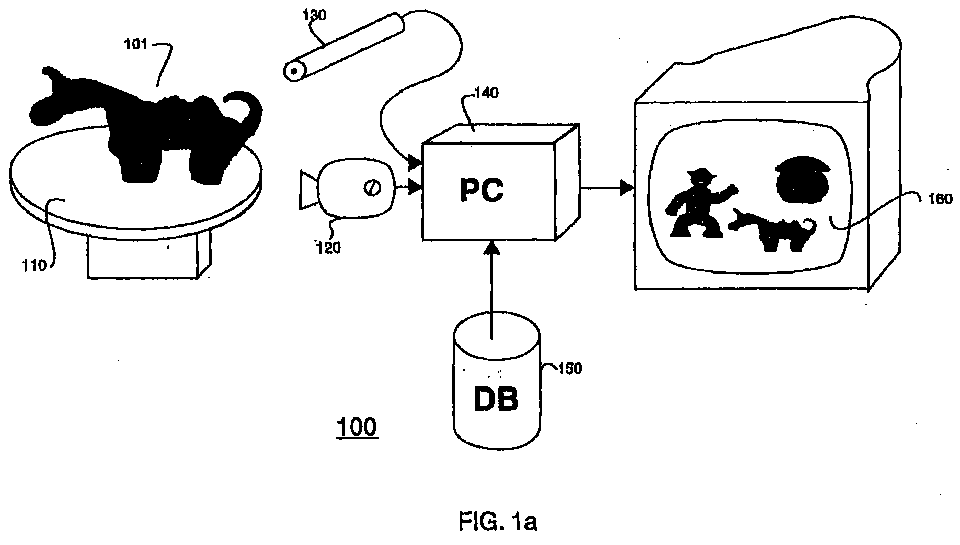
- FIG 1a shows an object recognition system 100 according to our invention.
- the system 100 includes a motorized turn-table table 110 for positioning a physical object 101.
- We construct the object from uniformly colored modeling clay.
- Clay was chosen because it is a modeling material that is easy to obtain and use.
- the clay can be used to model toy representations of common objects such as houses, people, animals, insects, furniture, cars, boats, planes, and the like, as shown in Figure 1b.
- the system 100 according to our invention can be used by a relatively unsophisticated user, for example, a small child, to populate a virtual reality world with animated characters and items of their own making.
- the user forms a toy model and places it on the turn-table.
- a camera 120 and an optional laser striper 130 scan the object while it rotates.
- the output of the camera and striper are processed by a computer system 140 to generate a volumetric scan.
- the computer system for example, a PC or laptop, has access to a database (DB) of 3D deformable templates 150.
- DB database
- the scan is compared to the stored three-dimensional deformable templates to identify the object.
- the scanned object can be parsed into its constituent parts to populate a virtual environment 160 with animated figures resembling the molded objects.
- System Operation Figure 2 is a flow diagram of a process 200 for recognizing scanned physical objects according to our invention.
- the object 101 to be scanned is placed upright and face forward on the turn-table 110. It is convenient for our comparing process to have the object placed in a known orientation. Inferring the orientation of the object is also possible. However, for applications that involve a cooperative user, inference of orientation is not necessary.
- the camera captures an image sequence 221 of the object while the object rotates and is scanned 230.
- a volumetric scan 231 is generated (230) from silhouettes. This is a well-known technique, for example, see Baumgart, "Geometric modeling for computer vision,” Technical Report AIM-249, AI Laboratory, Stanford University, Oct. 1974.
- volumetric data voxels, from 180 images taken a uniform 2° apart by the camera 120.
- This approach works well for most objects.
- an additional 180 images can be taken with the laser striper 130.
- silhouettes and laser striping is well suited to our smooth-surfaced and single-colored clay objects.
- a particular scanned volume is subsampled to a resolution of 128x128x128 voxels for the purpose of three-dimensional deformable template matching.
- Our recognition system 100 compares the scanned images 221 of the object to sets of parameterized object templates 150.
- the templates are deformed 250 to best match the object.
- Each match between a particular deformed template and the object is given a score 241.
- the maximum score is used to select 260 the best matching template 261, and the selected 3D template can be used to parse the object into its various constituent parts.
- the volumetric scan of the object is rendered and animated 270 according to the selected template, and viewed or manipulated in the virtual world 160.
- each template represents a physical object as a number of articulated links.
- the templates in Figures 3a-3m respectively represent a house, a bicycle, a bird, a bridge, an insect, a chair, a tree, a rocket, a table, a boat, a biped, a car, and a quadruped.
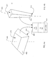
- each link is in the form of a truncated rectangular pyramid 400, hereinafter a link.
- a truncated rectangular pyramid has two rectangular bases 410-411 that are orthogonal to a major axis 420.
- Each link is completely defined by ten parameters , the two length and width ( l, w ) parameters of each base, and the three ( x, y, z ) coordinates of the center of each base (2x5).
- Each link also has an associated link label 421, e.g., "left-leg,” “roof,” or, "head.”
- each voxel generated receives the link label 421 of the associated part.
- the links can be connected to each other at their corners (eight), at the centers of any of their faces (six), or any other easy-to-compute connecting point.
- each object category we store a set of three-dimensional deformable templates 500 in the database 150 of Figure 1, for example ten.
- the templates for a particular object category here a biped, differ only in the relative proportions and orientations of their constituent links. This provides the comparing process with multiple starting points, one starting point for each of the ten templates in the set, thereby reducing any chances of matching on object parts in ways that are locally optimal but globally inferior.
- a number of the template parameters are constrained relative to each other. Some of these constraints derive implicitly from the enforced connectedness of links in a particular articulated linkage. Other constraints are the result of explicit constraints that apply to link-size parameters, e.g., a constraint that the dimensions of the base rectangles for both arm links in a biped should be the same.
- the number of free parameters for a six link biped template reduces to a manageable number, twenty-five.
- the comparing and matching process 200 can deform a template to best match a volumetric scan of a given physical object.
- templates can sometimes achieve excellent superposition and excess scores through educa contortions. Deformation beyond a certain threshold is therefore penalized by an exponential function of the distance between the original and deformed ( l, w ) parameters and the ( x, y, z ) coordinates of the links.
- the normalization function divides the superposition and excess terms by the number of occupied voxels in the scanned volume, which normalizes for the volume of the object ( V ).
- the deformation term is divided by the number of link vertices, normalizing for the complexity of the object template ( v ).
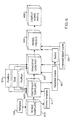
- the comparing and matching 600 proceeds as shown in Figure 6.
- the comparing is performed against all object templates 150, ten for each category of object.
- the template 150 is adjusted for fit in step 610. We do this by scaling the template in all three dimensions so that all of the link endpoints lie just within a bounding box surrounding the scanned object. There is no need to normalize the template for orientation because we assume that scanned objects have been placed upright and facing forward.
- the scaled template 611 is rasterized 620 to generate a corresponding volumetric data set (voxels) 621 that can be compared with the scanned volumetric data 231.
- the selected template is used to parse 640 the object into its constituent volumetric parts 650. For example, if an object is recognized as a biped, then the matching biped template is used to classify the object voxels that constitute the head, arms, legs, and torso by labeling the object voxels with the template label and the link labels 421 of Figure 4, for example, "biped_left-leg.”
- Our voxel classification is based on the shortest distance from each voxel of the scanned object to each voxel of the rasterized link throughout the space occupied by the scanned object. Voxels are then assigned to their closest links. If there are ties, the ties are broken by considering the distance to the center axes of the link, i.e., the line segment that connects the center of the bases of the link.
- the data representing the object can be manipulated in various ways depending on the application.
- the object can be brought to life in a virtual world environment.
- body measurements, masses, and moments of inertia can be specified. These values can be passed as input to an adaptive control and simulation system for a four-legged robot, which adapts an existing control system to the dynamics of this particular object.
- the motion data computed by the simulation can be used to animate the object template, which in turn animates the scanned volume by moving its voxels in concert with the links of the template to which they were assigned in the parsing phase.
- our invention allows an unsophisticated user to mold animate and inanimate objects using simple-to-manipulate modeling clay.
- the objects are automatically recognized, and constituent parts of the objects can be identified.
- a volume scan of the object can be manipulated at the part level to generate an animation sequence populated with things that exactly resemble the molded objects.
Landscapes
- Engineering & Computer Science (AREA)
- Computer Vision & Pattern Recognition (AREA)
- Theoretical Computer Science (AREA)
- Medical Informatics (AREA)
- Computing Systems (AREA)
- Databases & Information Systems (AREA)
- Evolutionary Computation (AREA)
- General Health & Medical Sciences (AREA)
- Artificial Intelligence (AREA)
- Software Systems (AREA)
- Health & Medical Sciences (AREA)
- Physics & Mathematics (AREA)
- General Physics & Mathematics (AREA)
- Multimedia (AREA)
- Processing Or Creating Images (AREA)
- Image Analysis (AREA)
Abstract
A method recognizes three-dimensional physical objects using three-dimensional
deformable templates. A particular object is scanned with a
camera to generate volumetric data representing the object. The volumetric
data is compared to each of a plurality of three-dimensional deformable
templates stored in a database to obtain a score for each comparison. The
deforming of the template is done by optimizing an objective function.
Description
- This invention relates generally to computer vision, and more particularly to recognizing scanned physical objects using deformable three-dimensional templates.
- A number of techniques are known for recognizing three-dimensional objects from two-dimensional images of the objects. Brooks, in "Model-based 3D interpretation of 2D images," IEEE Trans. on Pattern Analysis and Machine Intelligence, 5(2):140-150, 1983, describes the use of parameterized objects for object recognition. There the objects are generalized cylinders.
- Solina et al., in "Recovery of parametric models from range images," IEEE Trans. on Pattern Analysis and Machine Intelligence, 12(2):131-146, 1990, describe how to recover parametric objects from range data by minimizing surface distances, for example, using superquadrics with global deformations. There is no object recognition here.
- Dickenson et al. survey a number of different shape recovery techniques in "From volumes to views: An approach to 3D object recognition," Computer Vision, Graphics and Image Processing: Image Understanding, 55(2):130-154, 1992.
- Most prior art template matching methods do not use full volumetric templates. The templates are either two-dimensional for image matching, or in the case of range data, the templates are surface based. In addition, the prior art templates are relatively unconstrained to maximize the likelihood of matching. Unconstrained templates require the manipulation of a large number of parameters.
- Therefore, it is desired to provide a vision-based recognition system that can identify physical objects having multiple constituent parts. Furthermore, it is desired to parse the identified objects so that they can be animated in virtual environments.
- Provided is a computer vision system for recognizing and parsing common toy-like objects, such as people, animals, trees, houses, cars, boats, birds, insects, etc. A toy object can be made of modeling clay, or other suitable materials. Using a single calibrated camera, a sequence of images of the model object is acquired while the object is rotated on a turn-table. A 3D volumetric scan of the object is recovered from the sequence of 2D images. The volumetric scan is compared against sets of three-dimensional deformable templates. There is one set of three-dimensional deformable templates for each category of object. This process allows one to both classify the object and to identify its constituent parts. Using this information, it becomes possible to recognize and parse, for example, an ambulatory object, such as a biped or a quadruped, and to place the object in an appropriate virtual environment for animation.
- More particularly, a method recognizes three-dimensional physical objects using three-dimensional deformable templates. A particular object is scanned with a camera to generate volumetric data representing the object. The volumetric data is compared to each of a plurality of three-dimensional deformable templates stored in a database to obtain a score for each comparison. The templates are deformed while the score of an objective function is optimized.
- The three-dimensional deformable template that receives the highest score determines the category of the object, and the template is used to parse the object into its constituent parts, and the parts of the object can than be rendered and animated in a virtual world environment.
-
- Figure 1a is a block diagram of a recognition system according to the invention;
- Figure 1b shows clay models to be recognized by the system of Figure 1a;
- Figure 2 is a flow diagram of a process for recognizing physical objects;
- Figures 3a-3m depicts representative three-dimensional deformable templates used by the system of Figure 1;
- Figures 4a-4b are truncated rectangular pyramids used to form the volumetric templates of Figures 3a-3m;
- Figure 5 shows a set of three-dimensional deformable templates for one category; and
- Figure 6 is a flow diagram of a matching and parsing process according to the invention.
-
- System OverviewFigure 1a shows an
object recognition system 100 according to our invention. Thesystem 100 includes a motorized turn-table table 110 for positioning aphysical object 101. We construct the object from uniformly colored modeling clay. Clay was chosen because it is a modeling material that is easy to obtain and use. The clay can be used to model toy representations of common objects such as houses, people, animals, insects, furniture, cars, boats, planes, and the like, as shown in Figure 1b. - The
system 100 according to our invention can be used by a relatively unsophisticated user, for example, a small child, to populate a virtual reality world with animated characters and items of their own making. - The user forms a toy model and places it on the turn-table. A
camera 120 and anoptional laser striper 130 scan the object while it rotates. The output of the camera and striper are processed by acomputer system 140 to generate a volumetric scan. The computer system, for example, a PC or laptop, has access to a database (DB) of 3Ddeformable templates 150. The scan is compared to the stored three-dimensional deformable templates to identify the object. After the object has been recognized, the scanned object can be parsed into its constituent parts to populate avirtual environment 160 with animated figures resembling the molded objects. - System OperationFigure 2 is a flow diagram of a process 200 for recognizing scanned physical objects according to our invention. We calibrate (210) the camera from images of an object of known dimensions and placed at a fixed orientation on the turn-table. This
step 210 determines thecamera parameters 211. - The
object 101 to be scanned is placed upright and face forward on the turn-table 110. It is convenient for our comparing process to have the object placed in a known orientation. Inferring the orientation of the object is also possible. However, for applications that involve a cooperative user, inference of orientation is not necessary. - The camera captures an
image sequence 221 of the object while the object rotates and is scanned 230. Avolumetric scan 231 is generated (230) from silhouettes. This is a well-known technique, for example, see Baumgart, "Geometric modeling for computer vision," Technical Report AIM-249, AI Laboratory, Stanford University, Oct. 1974. - For example, we generate volumetric data, voxels, from 180 images taken a uniform 2° apart by the
camera 120. This approach works well for most objects. However, for objects that include significant concavities, we use the laser striper to refine the shape of the object. For example, an additional 180 images can be taken with thelaser striper 130. The use of silhouettes and laser striping is well suited to our smooth-surfaced and single-colored clay objects. A particular scanned volume is subsampled to a resolution of 128x128x128 voxels for the purpose of three-dimensional deformable template matching. - Our
recognition system 100 compares the scannedimages 221 of the object to sets of parameterizedobject templates 150. The templates are deformed 250 to best match the object. Each match between a particular deformed template and the object is given ascore 241. The maximum score is used to select 260 thebest matching template 261, and the selected 3D template can be used to parse the object into its various constituent parts. The volumetric scan of the object is rendered and animated 270 according to the selected template, and viewed or manipulated in thevirtual world 160. - As shown in Figure 3a-3m, each template represents a physical object as a number of articulated links. The templates in Figures 3a-3m respectively represent a house, a bicycle, a bird, a bridge, an insect, a chair, a tree, a rocket, a table, a boat, a biped, a car, and a quadruped.
- As shown in Figures 4a and 4b, each link is in the form of a truncated
rectangular pyramid 400, hereinafter a link. By definition, a truncated rectangular pyramid has two rectangular bases 410-411 that are orthogonal to amajor axis 420. Each link is completely defined by ten parameters , the two length and width (l, w) parameters of each base, and the three (x, y, z) coordinates of the center of each base (2x5). - Also associated with each template is a label uniquely identifying the template, for example, "biped," or "house." Each link also has an associated
link label 421, e.g., "left-leg," "roof," or, "head." - As an advantage, rasterizing links to determine what 3D space they occupy is relatively easy which makes the comparing of physical objects to our three-dimensional deformable templates efficient. During rasterization, each voxel generated receives the
link label 421 of the associated part. - The links can be connected to each other at their corners (eight), at the centers of any of their faces (six), or any other easy-to-compute connecting point.
- As shown in Figure 5, for each object category, we store a set of three-dimensional deformable templates 500 in the
database 150 of Figure 1, for example ten. The templates for a particular object category, here a biped, differ only in the relative proportions and orientations of their constituent links. This provides the comparing process with multiple starting points, one starting point for each of the ten templates in the set, thereby reducing any chances of matching on object parts in ways that are locally optimal but globally inferior. - A number of the template parameters are constrained relative to each other. Some of these constraints derive implicitly from the enforced connectedness of links in a particular articulated linkage. Other constraints are the result of explicit constraints that apply to link-size parameters, e.g., a constraint that the dimensions of the base rectangles for both arm links in a biped should be the same.
- When these constraints are applied, the number of free parameters for a six link biped template reduces to a manageable number, twenty-five. By modifying these parameters, the comparing and matching process 200 can deform a template to best match a volumetric scan of a given physical object.
- In our optimization-based approach, we quantify a best match by using an objective function f defined as:
- SuperpositionEach voxel occupied by both the rasterized object template and the scanned object contributes +1 to the superposition term of the objective-function.
- ExcessThe excess term penalizes voxels occupied by the rasterized template but not by the object. A simple approach would add a score of -1 for each such voxel. In order to obtain better results, we add a score of -r, where r is the distance to the nearest occupied voxel in the object. This value can be computed for each voxel by an efficient two-pass algorithm as described by Russ in "The Image Processing Handbook," CRC Press, 1998. The advantage of this distance-based penalty is that its gradient still gives useful information even when there is minimal overlap between the template and object.
- Without some penalty for excessive deformation, templates can sometimes achieve excellent superposition and excess scores through absurd contortions. Deformation beyond a certain threshold is therefore penalized by an exponential function of the distance between the original and deformed (l, w) parameters and the (x, y, z) coordinates of the links.
- The normalization function divides the superposition and excess terms by the number of occupied voxels in the scanned volume, which normalizes for the volume of the object (V). The deformation term is divided by the number of link vertices, normalizing for the complexity of the object template (v).
- Given this objective function f, the comparing and matching 600 proceeds as shown in Figure 6. The comparing is performed against all object
templates 150, ten for each category of object. First, thetemplate 150 is adjusted for fit instep 610. We do this by scaling the template in all three dimensions so that all of the link endpoints lie just within a bounding box surrounding the scanned object. There is no need to normalize the template for orientation because we assume that scanned objects have been placed upright and facing forward. - The scaled
template 611 is rasterized 620 to generate a corresponding volumetric data set (voxels) 621 that can be compared with the scannedvolumetric data 231. - Comparing applies a gradient-descent method to optimize the objective function f. We use the conjugate-gradient method of gradient-descent, approximating the partial derivatives of the objective function by central differences, see Press et al. in "Numerical Recipes in C," Cambridge University Press, 1988.
- For best results, we run the rasterizing and gradient-descent steps to quiescence three times in succession, for position, size, and again position 631. First, we vary only the location parameters of the link template, then only the size parameters, and finally only the location parameters again, rasterizing the template each run.
- We also schedule the relative weights of the objective-function terms over the three runs: the superposition and excess terms decrease in significance, and the deformation term increases. We determined reasonable values for the weights empirically.
- After the best-matching template has been found for a given object (the one with the maximum score), the selected template is used to parse 640 the object into its constituent volumetric parts 650. For example, if an object is recognized as a biped, then the matching biped template is used to classify the object voxels that constitute the head, arms, legs, and torso by labeling the object voxels with the template label and the link labels 421 of Figure 4, for example, "biped_left-leg."
- Our voxel classification, during parsing, is based on the shortest distance from each voxel of the scanned object to each voxel of the rasterized link throughout the space occupied by the scanned object. Voxels are then assigned to their closest links. If there are ties, the ties are broken by considering the distance to the center axes of the link, i.e., the line segment that connects the center of the bases of the link.
- After the object voxels have been parsed, the data representing the object can be manipulated in various ways depending on the application.
- After an object is recognized, the object can be brought to life in a virtual world environment. For example, for a quadruped, body measurements, masses, and moments of inertia can be specified. These values can be passed as input to an adaptive control and simulation system for a four-legged robot, which adapts an existing control system to the dynamics of this particular object.
- The motion data computed by the simulation can be used to animate the object template, which in turn animates the scanned volume by moving its voxels in concert with the links of the template to which they were assigned in the parsing phase.
- Care must be taken to avoid the introduction of tears and cracks in the object as it deforms during animation. For example, having all links influence the movement of a voxel in inverse proportion to the square of their distance from the voxel reduces tears at the junctions of different object regions.
- As an advantage, our invention allows an unsophisticated user to mold animate and inanimate objects using simple-to-manipulate modeling clay. The objects are automatically recognized, and constituent parts of the objects can be identified. Thus, a volume scan of the object can be manipulated at the part level to generate an animation sequence populated with things that exactly resemble the molded objects.
It is to be understood that various other adaptations and modifications may be made within the spirit and scope of the invention. Therefore, it is the object of the appended claims to cover all such variations and modifications as come within the true spirit and scope of the invention.
Claims (19)
- A method for recognizing a physical object using templates, comprising the steps of:scanning the object to generate volumetric data representing the object;comparing the volumetric data to a plurality of sets of three-dimensional deformable templates stored in a database to obtain scores; andselecting a particular three-dimensional deformable template that matches the volumetric data based on a maximum score.
- The method of claim 1 wherein the object is scanned with a camera while rotating;
- The method of claim 1 wherein the object is scanned with a laser striper to generate surface detail.
- The method of claim 1 wherein each three-dimensional deformable template is formed from connected links.
- The method of claim 4 wherein each link is in the form of a truncated rectangular pyramid having two bases orthogonal to a major axis of the link, and four faces.
- The method of claim 5 wherein each link is defined by length and width parameters of each base, and the x, y, z parameters of the center of each base.
- The method of claim 4 wherein the links are connected to each other at corners of the links.
- The method of claim 5 wherein the links are connected to each other at the centers of any of the faces.
- The method of claim 1 further comprising the steps of:scoring each comparison between the volumetric data and each three-dimensional deformable template using an objective function f.
- The method of claim 9 wherein
- The method of claim 10 wherein each voxel occupied by both the rasterized three-dimensional deformable template and the volumetric data contributes +1 to the superposition term of the objective function.
- The method of claim 10 wherein the excess term penalizes voxels occupied by the rasterized three-dimensional deformable template but not by the volumetric data.
- The method of claim 10 wherein the deformation term penalizes excessive deformation exponentially.
- The method of claim 10 wherein the superposition term and the excess terms are divided by the number of occupied voxels in the volumetric data, and the deformation is divided by the number of link vertices.
- The method of claim 1 further including the steps of:scaling each three-dimensional deformable template to fit the volumetric data;rasterizing the scaled three-dimensional deformable template; andapplying a gradient descent to optimize an objective function to generate the scores.
- The method of claim 1 further including parsing the volumetric data using the particular three-dimensional deformable template.
- The method of claim 16 wherein the volumetric data are labeled according to labels associated with the particular thee-dimensional deformable template.
- The method of claim 16 further including animating the parsed volumetric data in a virtual environment.
- A system for recognizing physical object using templates, comprising:a camera scanning the object to generate volumetric data representing the object;means for comparing the volumetric data to a plurality of sets of three-dimensional deformable templates stored in a database to obtain scores; andmeans for selecting a particular three-dimensional deformable template that matches the volumetric data based on a maximum score.
Applications Claiming Priority (2)
| Application Number | Priority Date | Filing Date | Title |
|---|---|---|---|
| US262376 | 1999-03-04 | ||
| US09/262,376 US6259815B1 (en) | 1999-03-04 | 1999-03-04 | System and method for recognizing scanned objects with deformable volumetric templates |
Publications (1)
| Publication Number | Publication Date |
|---|---|
| EP1035494A2 true EP1035494A2 (en) | 2000-09-13 |
Family
ID=22997233
Family Applications (1)
| Application Number | Title | Priority Date | Filing Date |
|---|---|---|---|
| EP00102461A Withdrawn EP1035494A2 (en) | 1999-03-04 | 2000-02-04 | System and method for recognizing scanned objects with deformable volumetric templates |
Country Status (3)
| Country | Link |
|---|---|
| US (1) | US6259815B1 (en) |
| EP (1) | EP1035494A2 (en) |
| JP (1) | JP3441690B2 (en) |
Families Citing this family (42)
| Publication number | Priority date | Publication date | Assignee | Title |
|---|---|---|---|---|
| US6766058B1 (en) * | 1999-08-04 | 2004-07-20 | Electro Scientific Industries | Pattern recognition using multiple templates |
| US20020055861A1 (en) * | 2000-11-08 | 2002-05-09 | King Daniel A. | Claiming system and method |
| US20020138218A1 (en) * | 2001-03-22 | 2002-09-26 | Williams Richard Ernest | Method and device for robust pattern recognition |
| US20030161505A1 (en) * | 2002-02-12 | 2003-08-28 | Lawrence Schrank | System and method for biometric data capture and comparison |
| US8064684B2 (en) * | 2003-04-16 | 2011-11-22 | Massachusetts Institute Of Technology | Methods and apparatus for visualizing volumetric data using deformable physical object |
| US7263209B2 (en) * | 2003-06-13 | 2007-08-28 | Sarnoff Corporation | Vehicular vision system |
| DE10335601B4 (en) * | 2003-08-04 | 2016-01-14 | Robert Bosch Gmbh | Object classification method using a 3D model database |
| US20070043439A1 (en) * | 2005-08-17 | 2007-02-22 | Becker Theodore J | Method of assembling a graphical image biomechanical supplement |
| US8150101B2 (en) * | 2006-11-13 | 2012-04-03 | Cybernet Systems Corporation | Orientation invariant object identification using model-based image processing |
| US8498454B2 (en) * | 2009-07-14 | 2013-07-30 | General Electric Company | Optimal subspaces for face recognition |
| CN102713931A (en) | 2009-08-04 | 2012-10-03 | 艾修视力科技有限公司 | System and method for object extraction |
| US9595108B2 (en) | 2009-08-04 | 2017-03-14 | Eyecue Vision Technologies Ltd. | System and method for object extraction |
| US8285057B2 (en) * | 2010-05-14 | 2012-10-09 | Palo Alto Research Center Incorporated | Learning image anchor templates for document classification |
| US8285058B2 (en) * | 2010-05-14 | 2012-10-09 | Palo Alto Research Center Incorporated | Learning image templates for content anchoring and data extraction |
| US9728001B2 (en) * | 2011-09-23 | 2017-08-08 | Real-Scan, Inc. | Processing and rendering of large image files |
| US9336625B2 (en) | 2011-10-25 | 2016-05-10 | Microsoft Technology Licensing, Llc | Object refinement using many data sets |
| KR101356544B1 (en) * | 2012-03-29 | 2014-02-19 | 한국과학기술원 | Method and apparatus for generating 3d stereoscopic image |
| US9715761B2 (en) | 2013-07-08 | 2017-07-25 | Vangogh Imaging, Inc. | Real-time 3D computer vision processing engine for object recognition, reconstruction, and analysis |
| WO2015026874A1 (en) * | 2013-08-19 | 2015-02-26 | Nant Holdings Ip, Llc | Metric based recognition, systems and methods |
| GB2532075A (en) * | 2014-11-10 | 2016-05-11 | Lego As | System and method for toy recognition and detection based on convolutional neural networks |
| US9710960B2 (en) | 2014-12-04 | 2017-07-18 | Vangogh Imaging, Inc. | Closed-form 3D model generation of non-rigid complex objects from incomplete and noisy scans |
| US10089772B2 (en) | 2015-04-23 | 2018-10-02 | Hasbro, Inc. | Context-aware digital play |
| DK180058B1 (en) * | 2018-07-06 | 2020-02-27 | Lego A/S | toy system |
| US20230065252A1 (en) * | 2015-08-17 | 2023-03-02 | Lego A/S | Toy system and a method of operating the toy system |
| US11504623B2 (en) | 2015-08-17 | 2022-11-22 | Lego A/S | Method of creating a virtual game environment and interactive game system employing the method |
| US10600240B2 (en) | 2016-04-01 | 2020-03-24 | Lego A/S | Toy scanner |
| EP3481519A1 (en) | 2016-07-05 | 2019-05-15 | Lego A/S | Method for creating a virtual object |
| US11433310B2 (en) * | 2016-07-05 | 2022-09-06 | Lego A/S | Method for creating a virtual object |
| KR101733657B1 (en) * | 2016-07-28 | 2017-05-11 | (주)유디피 | System for object counter using camera based on range image and counting method thereof |
| US10380762B2 (en) | 2016-10-07 | 2019-08-13 | Vangogh Imaging, Inc. | Real-time remote collaboration and virtual presence using simultaneous localization and mapping to construct a 3D model and update a scene based on sparse data |
| WO2018188088A1 (en) * | 2017-04-14 | 2018-10-18 | 广州千藤玩具有限公司 | Clay toy system based on augmented reality and digital image processing and method therefor |
| US10839585B2 (en) | 2018-01-05 | 2020-11-17 | Vangogh Imaging, Inc. | 4D hologram: real-time remote avatar creation and animation control |
| US11080540B2 (en) | 2018-03-20 | 2021-08-03 | Vangogh Imaging, Inc. | 3D vision processing using an IP block |
| US10810783B2 (en) | 2018-04-03 | 2020-10-20 | Vangogh Imaging, Inc. | Dynamic real-time texture alignment for 3D models |
| US11170224B2 (en) | 2018-05-25 | 2021-11-09 | Vangogh Imaging, Inc. | Keyframe-based object scanning and tracking |
| US12203742B2 (en) | 2018-06-29 | 2025-01-21 | Photogauge, Inc. | System and method for digital-representation-based flight path planning for object imaging |
| US10885622B2 (en) | 2018-06-29 | 2021-01-05 | Photogauge, Inc. | System and method for using images from a commodity camera for object scanning, reverse engineering, metrology, assembly, and analysis |
| US11232633B2 (en) | 2019-05-06 | 2022-01-25 | Vangogh Imaging, Inc. | 3D object capture and object reconstruction using edge cloud computing resources |
| US11170552B2 (en) | 2019-05-06 | 2021-11-09 | Vangogh Imaging, Inc. | Remote visualization of three-dimensional (3D) animation with synchronized voice in real-time |
| JP7376268B2 (en) * | 2019-07-22 | 2023-11-08 | ファナック株式会社 | 3D data generation device and robot control system |
| US11335063B2 (en) | 2020-01-03 | 2022-05-17 | Vangogh Imaging, Inc. | Multiple maps for 3D object scanning and reconstruction |
| US12496721B2 (en) | 2020-05-08 | 2025-12-16 | Samsung Electronics Co., Ltd. | Virtual presence for telerobotics in a dynamic scene |
Family Cites Families (3)
| Publication number | Priority date | Publication date | Assignee | Title |
|---|---|---|---|---|
| US5768413A (en) * | 1995-10-04 | 1998-06-16 | Arch Development Corp. | Method and apparatus for segmenting images using stochastically deformable contours |
| US6009212A (en) * | 1996-07-10 | 1999-12-28 | Washington University | Method and apparatus for image registration |
| US5926568A (en) * | 1997-06-30 | 1999-07-20 | The University Of North Carolina At Chapel Hill | Image object matching using core analysis and deformable shape loci |
-
1999
- 1999-03-04 US US09/262,376 patent/US6259815B1/en not_active Expired - Lifetime
-
2000
- 2000-02-04 EP EP00102461A patent/EP1035494A2/en not_active Withdrawn
- 2000-02-15 JP JP2000036780A patent/JP3441690B2/en not_active Expired - Fee Related
Also Published As
| Publication number | Publication date |
|---|---|
| JP2000259827A (en) | 2000-09-22 |
| JP3441690B2 (en) | 2003-09-02 |
| US6259815B1 (en) | 2001-07-10 |
Similar Documents
| Publication | Publication Date | Title |
|---|---|---|
| US6259815B1 (en) | System and method for recognizing scanned objects with deformable volumetric templates | |
| US11514642B2 (en) | Method and apparatus for generating two-dimensional image data describing a three-dimensional image | |
| CN101751689B (en) | A 3D Face Reconstruction Method | |
| Kästner et al. | A 3d-deep-learning-based augmented reality calibration method for robotic environments using depth sensor data | |
| US20040190775A1 (en) | Viewpoint-invariant detection and identification of a three-dimensional object from two-dimensional imagery | |
| CN110168477B (en) | Deep learning system for cuboid detection | |
| US20040227760A1 (en) | Statistical dynamic collisions method and apparatus | |
| US20040227761A1 (en) | Statistical dynamic modeling method and apparatus | |
| CN114842136B (en) | A single-image 3D face reconstruction method based on differentiable renderer | |
| US12573161B2 (en) | Learning articulated shape reconstruction from imagery | |
| JPH08212329A (en) | Adaptive recognition system | |
| CN112836680A (en) | A Vision-Based Facial Expression Recognition Method | |
| Monica et al. | Point cloud projective analysis for part-based grasp planning | |
| US12367649B2 (en) | Generating a facial-hair-free mesh of a subject | |
| US20240096016A1 (en) | System And Method For Virtual Object Asset Generation | |
| CN119540494A (en) | A single-view 3D reconstruction method for pigs based on deep learning | |
| Venkatesh et al. | On the simultaneous recognition of identity and expression from BU-3DFE datasets | |
| Qi et al. | Air-embodied: An efficient active 3dgs-based interaction and reconstruction framework with embodied large language model | |
| Hamandi et al. | Generating distinctive marker configurations for robot detection in motion capture systems | |
| Bhanu et al. | CAGD based 3-D vision | |
| Zherdeva et al. | Prediction of human behavior with synthetic data | |
| Hamarneh et al. | Physics-based shape deformations for medical image analysis | |
| Bhanu et al. | 3-D model building using CAGD techniques | |
| KR102904365B1 (en) | Method and 3d auto-labeling device for generating training data to be used for monocular 3d object detection model, and learning method and learning device using the same | |
| Gomez et al. | Superquadric indoor scene representation for orientation and navigation tasks |
Legal Events
| Date | Code | Title | Description |
|---|---|---|---|
| PUAI | Public reference made under article 153(3) epc to a published international application that has entered the european phase |
Free format text: ORIGINAL CODE: 0009012 |
|
| AK | Designated contracting states |
Kind code of ref document: A2 Designated state(s): AT BE CH CY DE DK ES FI FR GB GR IE IT LI LU MC NL PT SE |
|
| AX | Request for extension of the european patent |
Free format text: AL;LT;LV;MK;RO;SI |
|
| STAA | Information on the status of an ep patent application or granted ep patent |
Free format text: STATUS: THE APPLICATION HAS BEEN WITHDRAWN |
|
| 18W | Application withdrawn |
Effective date: 20040423 |