EP1035409A2 - Method and apparatus for measurement of light from illuminated specimen eliminating influence of background light - Google Patents
Method and apparatus for measurement of light from illuminated specimen eliminating influence of background light Download PDFInfo
- Publication number
- EP1035409A2 EP1035409A2 EP00102884A EP00102884A EP1035409A2 EP 1035409 A2 EP1035409 A2 EP 1035409A2 EP 00102884 A EP00102884 A EP 00102884A EP 00102884 A EP00102884 A EP 00102884A EP 1035409 A2 EP1035409 A2 EP 1035409A2
- Authority
- EP
- European Patent Office
- Prior art keywords
- measurement
- light
- specimen
- measurement result
- duration
- Prior art date
- Legal status (The legal status is an assumption and is not a legal conclusion. Google has not performed a legal analysis and makes no representation as to the accuracy of the status listed.)
- Granted
Links
Images






Classifications
-
- G—PHYSICS
- G01—MEASURING; TESTING
- G01N—INVESTIGATING OR ANALYSING MATERIALS BY DETERMINING THEIR CHEMICAL OR PHYSICAL PROPERTIES
- G01N21/00—Investigating or analysing materials by the use of optical means, i.e. using sub-millimetre waves, infrared, visible or ultraviolet light
- G01N21/62—Systems in which the material investigated is excited whereby it emits light or causes a change in wavelength of the incident light
- G01N21/63—Systems in which the material investigated is excited whereby it emits light or causes a change in wavelength of the incident light optically excited
- G01N21/64—Fluorescence; Phosphorescence
-
- G—PHYSICS
- G01—MEASURING; TESTING
- G01N—INVESTIGATING OR ANALYSING MATERIALS BY DETERMINING THEIR CHEMICAL OR PHYSICAL PROPERTIES
- G01N21/00—Investigating or analysing materials by the use of optical means, i.e. using sub-millimetre waves, infrared, visible or ultraviolet light
- G01N21/17—Systems in which incident light is modified in accordance with the properties of the material investigated
- G01N21/47—Scattering, i.e. diffuse reflection
Definitions
- the present invention relates to an optical measurement method and an optical measurement apparatus for performing measurement of light which has been emitted from a specimen in response to illumination of the specimen, or has been reflected by or has penetrated through a specimen when the specimen is illuminated, under a condition that background light behaves as background noise.
- the background light is caused, for example, by room illumination.
- An optical measurement apparatus performing measurement of light as described above is conventionally known.
- the exposure time is made so short, for example, not longer than 100 nsec, that the background light does not affect measurement data.
- a short-pulse light source and a high-speed, high-sensitivity detector e.g., an image intensifier
- these components are expensive, and therefore increase the manufacturing cost of the measurement apparatus. From the viewpoint of cost reduction, it is not possible to use such expensive components.
- the exposure time cannot be shortened to less then one micrometer when an inexpensive laser diode and charge-coupled device (CCD) are used.
- CCD charge-coupled device
- the influence of the background light cannot be eliminated by use of the inexpensive laser diode and charge-coupled device (CCD). Further, even if the laser diode is driven to emit a short-pulse beam and the image intensifier is used for detection, it is not possible to obtain a high peak with a usual operation of driving the laser diode. That is, sufficient exposure energy cannot be supplied to a specimen with the above construction.
- CCD charge-coupled device
- the first object of the present invention is to provide an optical measurement method and an optical measurement apparatus which can perform measurement of light with high accuracy even when the wavelength range of the background light overlaps the wavelength range of the light to be measured, which has been emitted from a specimen, or has been reflected by or has penetrated through a specimen when the specimen is illuminated.
- the second object of the present invention is to provide an optical measurement method and an optical measurement apparatus enabling precise measurement of light which has been emitted from a specimen, or has been reflected by or has penetrated through a specimen when the specimen is illuminated, under a plurality of types of background light respectively having a plurality of different periods of cyclic intensity variations.
- an optical measurement method for performing measurement of first light, which has been emitted from or reflected by a specimen, or has penetrated through the specimen, under background light having an intensity which varies cyclically with a period.
- the method contains steps of: (a) performing a first operation of measuring the first light for a first duration beginning at a first time, while illuminating the specimen with second light, to obtain a first measurement result; (b) performing a second operation of measuring the first light for a second duration having the same length as the first duration and beginning at a second time which is different from the first time by an integer multiple of the above period, while illumination of the specimen is stopped, to obtain a second measurement result; and (C) subtracting the second measurement result from the first measurement result, to obtain a third measurement result which is not affected by the background light.
- an optical measurement apparatus for performing measurement of first light, which has been emitted from or reflected by a specimen, or has penetrated through the specimen, under background light having intensity which varies cyclically with a period.
- the apparatus contains a first measurement unit which performs a first operation of measuring the first light while illuminating the specimen by second light, to obtain a first measurement result; a second measurement unit which performs a second operation of measuring the first light while illumination of the specimen is stopped, to obtain a second measurement result; a control unit which controls timing of the operations of the first and second measurement units so that the first operation is performed for a first duration beginning at a first time, and the second operation is performed for a second duration having the same length as the first duration and beginning at a second time which is different from the first time by an integer multiple of the above period; and a calculation unit which obtains a third measurement result, which is not affected by the background light, by subtracting the second measurement result from the first measurement result.
- the difference between the beginning times of the first and second operations of measuring the first light is an integer multiple of the period of the cyclic variation of the intensity of the background light, and the first and second operations are performed for the same length of time. Since the specimen is not illuminated with the second light during the second operation, it is considered that an amount of influence by the background light included in the first measurement result of the first operation will be the same as the amount of the second measurement result of the second operation. Therefore, it is expected that the amount of influence by the background light included in the first measurement result of the first operation will be removed by subtracting the amount of the second measurement result of the second operation from the amount of the first result of the first operation.
- a final (third) measurement result can be obtained with high accuracy even when the wavelength range of the background light overlaps the wavelength range of the light to be measured, which has been emitted from a specimen in response to illumination of the specimen, or has been reflected by or has penetrated through a specimen when the specimen is illuminated.
- an optical measurement method for performing measurement of first light which has been emitted from or reflected by a specimen, or has penetrated through the specimen, under background light having an intensity which varies cyclically with a period.
- the method contains steps of: (a) performing a first operation of measuring the first light for a first duration having a length equal to an integer multiple of the above period, while illuminating the specimen by second light, to obtain a first measurement result; (b) performing a second operation of measuring the first light for a second duration having a length equal to the length of the first duration, while illumination of the specimen is stopped, to obtain a second measurement result; and (c) subtracting the second measurement result from the first measurement result, to obtain a third measurement result which is not affected by the background light.
- an optical measurement apparatus for performing measurement of first light, which has been emitted from or reflected by a specimen, or has penetrated through the specimen, under background light having an intensity which varies cyclically with a period.
- the apparatus contains a first measurement unit which performs a first operation of measuring the first light while illuminating the specimen with second light to obtain a first measurement result; a second measurement unit which performs a second operation of measuring the first light while illumination of the specimen is stopped, to obtain a second measurement result; and a control unit which controls timing of the operations of the first and second measurement units so that each of the first and second operations is performed for a duration having an identical length equal to an integer multiple of the above period; and a calculation unit which obtains a third measurement result, which is not affected by the background light, by subtracting the second measurement result from the first measurement result.
- the first and second operations are also performed for the same length of time, and the length is equal to an integer multiple of the above period of the cyclic variation of the intensity of the background light. It is expected that an amount of influence by the background light on a measuring operation for an identical length of time will not change regardless of the beginning time of the measuring operation, when the length of time is equal to an integer multiple of the above period of the cyclic variation of the intensity of the background light. Since the specimen is not illuminated by the second light during the second operation, regardless of the beginning times of the first and second operations, it is expected that an amount of influence by the background light included in the first measurement result of the first operation will be the same as the amount of the second measurement result of the second operation.
- the amount of influence by the background light included in the first measurement result of the first operation will be removed by subtracting the amount of the second measurement result of the second operation from the amount of the first measurement result of the first operation.
- a final measurement result can be obtained with high accuracy even when the wavelength range of the background light overlaps the wavelength range of the light to be measured, which has been emitted from a specimen in response to illumination of the specimen, or has been reflected by or has penetrated through a specimen when the specimen is illuminated.
- the period may be obtained by measuring the intensity of the background light.
- the period obtained based on the measured intensity of the background light is used for controlling the timing of the measurement operations in the present invention, an accurate value of the period can be used, and therefore the measurement can be performed with higher accuracy.
- each of the first and second operations may or may not be performed in synchronization with the cyclic variation of the background light.
- first light which has been emitted from a specimen may be reradiation light such as fluorescent light, Raman scattering light, phosphorescent light, or the like.
- first light which has been "reflected by a specimen” may be light which has been polarized due to the reflection, or has a spectrum not containing a portion of components which has been absorbed by the specimen, or has intensity reduced due to the reflection in accordance with reflectance of the specimen, or has been changed by any combination of polarization, absorption of a spectrum component, and intensity reduction.
- first light which has penetrated through the specimen
- first light may be light which has been polarized during the penetration, or has a spectrum not containing a portion of components which is absorbed by the specimen during the penetration, or has intensity reduced during the penetration in accordance with transmittance of the specimen, or has been changed by any combination of polarization, absorption of a spectrum component, and intensity reduction.
- the above-mentioned "measurement of light” may include spectrum measurement of light and quantitative or qualitative measurement of intensity of light, and the measurement may be performed at one measurement point or at a number of measurement points.
- the measurement may be performed by obtaining information on an image containing the measurement points, where such an image may be obtained by using a charge-coupled device (CCD).
- CCD charge-coupled device
- an optical measurement method for performing measurement of first light, which has been emitted from or reflected by a specimen, or has penetrated through the specimen, under a plurality of types of background light respectively having a plurality of different periods with which intensities of the plurality of types of background light vary cyclically.
- the method contains steps of: (a) performing a first operation of measuring the first light for a first duration having a length equal to an integer multiple of the least common multiple of the plurality of different periods, while illuminating the specimen with second light, to obtain a first measurement result; (b) performing a second operation of measuring the first light for a second duration having a length equal to the length of the first duration, while illumination of the specimen is stopped, to obtain a second measurement result; and (c) subtracting the second measurement result from the first measurement result, to obtain a third measurement result which is not affected by the plurality of types of background light.
- an optical measurement apparatus for performing measurement of first light, which has been emitted from or reflected by a specimen, or has penetrated through the specimen, under a plurality of types of background light respectively having a plurality of different periods with which intensities of the plurality of types of background light vary cyclically.
- the apparatus contains a first measurement unit which performs a first operation of measuring the first light while illuminating the specimen with second light, to obtain a first measurement result; a second measurement unit which performs a second operation of measuring the first light while illumination of the specimen is stopped, to obtain a second measurement result; a control unit which controls timing of the operations of the first and second measurement units so that each of the first and second operations is performed for a duration having an identical length equal to an integer multiple of the least common multiple of the plurality of different periods; and a calculation unit which obtains a third measurement result, which is not affected by the plurality of types of background light, by subtracting the second measurement result from the first measurement result.
- the first and second operations are performed for the same length of time, and the length is equal to an integer multiple of the least common multiple of the plurality of different periods of the cyclic variations of the intensities of the plurality of types of background light. It is expected that an amount of influence of the plurality of types of background light on a measuring operation for an identical length of time will not change regardless of the beginning time of the measuring operation, when the length of time is equal to an integer multiple of the least common multiple of the plurality of different periods of the cyclic variations of the intensities of the plurality of types of background light.
- the specimen Since the specimen is not illuminated with the second light during the second operation, regardless of the beginning times of the first and second operations, it is expected that an amount of influence of the plurality of types of background light included in the first measurement result of the first operation will be the same as the amount of the second measurement result of the second operation. Therefore, it is expected that the influence of the plurality of types of background light included in the first measurement result of the first operation will be removed by subtracting the amount of the second measurement result of the second operation from the amount of the first measurement result of the first operation.
- a final measurement result can be obtained with high accuracy even when the wavelength ranges of the plurality of types of background light overlap the wavelength range of the light to be measured, which has been emitted from a specimen in response to illumination of the specimen, or has been reflected by or has penetrated through a specimen when the specimen is illuminated.
- an optical measurement method for performing measurement of first light, which has been emitted from or reflected by a specimen, or has penetrated through the specimen, under a plurality of types of background light respectively having a plurality of different periods with which intensities of the plurality of types of background light vary cyclically.
- the method contains steps of: (a) performing a first operation of measuring the first light for a first duration beginning at a first time, while illuminating the specimen with second light, to obtain a first measurement result; (b) performing a second operation of measuring the first light for a second duration having the same length as the first duration and beginning at a second time which is different from the first time by an integer multiple of the least common multiple of the plurality of different periods, while illumination of the specimen is stopped, to obtain a second measurement result; and (c) subtracting the second measurement result from the first measurement result, to obtain a third measurement result which is not affected by the plurality of types of background light.
- an optical measurement apparatus for performing measurement of first light, which has been emitted from or reflected by a specimen, or has penetrated through the specimen, under a plurality of types of background light respectively having a plurality of different periods with which intensities of the plurality of types of background light vary cyclically.
- the apparatus contains a first measurement unit which performs a first operation of measuring the first light while illuminating the specimen with second light, to obtain a first measurement result; a second measurement unit which performs a second operation of measuring the first light while illumination of the specimen is stopped, to obtain a second measurement result; a control unit which controls timing of the operations of the first and second measurement units so that the first operation is performed for a first duration beginning at a first time, and the second operation is performed for a second duration having the same length as the first duration and beginning at a second time which is different from the first time by an integer multiple of the least common multiple of the plurality of different periods; and a calculation unit which obtains a third measurement result, which is not affected by the plurality of types of background light, by subtracting the second measurement result from the first measurement result.
- the optical measurement method according to the seventh aspect of the present invention, or in the optical measurement apparatus according to the eighth aspect of the present invention may have the following additional features (i) to (iv).
- the first and second operations are performed for the same length of time, and the length is equal to an integer multiple of the least common multiple of at least one period, among the plurality of different periods, of at least one cyclic variation of the intensity or intensities of at least one type of background light corresponding to the at least one period. It is expected that an amount of influence of the at least one type of background light on a measuring operation for an identical length of time will not change regardless of the beginning time of the measuring operation, when the length of time is equal to an integer multiple of the least common multiple of the at least one period of the at least one cyclic variation of the intensity or intensities of the at least one type of background light corresponding to the at least one period.
- the specimen is not illuminated with the second light during the second operation, regardless of the beginning times of the first and second operations, it is expected that an amount of influence by the at least one type of background light included in the first measurement result of the first operation will be the same as the amount of the second measurement result of the second operation. Therefore, it is expected that the amount of influence by the at least one type of background light included in the first measurement result of the first operation will be removed by subtracting the amount of the second measurement result of the second operation from the amount of the first measurement result of the first operation.
- the difference between the beginning times of the first and second operations of measuring the first light is an integer multiple of the least common multiple of the rest of the plurality of different periods other than the at least one period, and the first and second operations are performed for the same length of time. Since the specimen is not illuminated by the second light during the second operation, it is considered that an amount of influence of the rest of the plurality of types of background light other than the above-mentioned at least one type of background light corresponding to the rest of the plurality of different periods other than the at least one period, included in the first measurement result of the first operation, will be the same as the amount of a component of the second measurement result generated by the rest of the plurality of types of background light other than the at least one type of background light.
- the amount of influence of the rest of the plurality of types of background light other than the at least one type of background light, included in the first measurement result of the first operation will be removed by subtracting the amount of the second measurement result of the second operation from the amount of the first result of the first operation.
- the amount of influence of all of the plurality of types of background light included in the first measurement result of the first operation will be removed by subtracting the amount of the second measurement result of the second operation from the amount of the first result of the first operation, and a final (third) measurement result can be obtained with high accuracy even when the wavelength range of the background light overlaps the wavelength range of the light to be measured, which has been emitted from a specimen in response to illumination of the specimen, or has been reflected by or has penetrated through a specimen when the specimen is illuminated.
- the plurality of types of background light means a plurality of types of background light which are required to be eliminated from the measurement result.
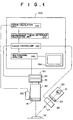
- Fig. 1 is a diagram illustrating an outline of the construction of an apparatus for measuring a spectrum of fluorescent light, as a first embodiment of the present invention.
- the apparatus of Fig. 1 executes the method according to the first aspect of the present invention, and therefore realizes the apparatus according to the second aspect of the present invention.
- the optical measurement apparatus as the first embodiment of the present invention contains a light source 20, a shutter 30, an optical condenser system 40, a spectrometer 50, an optical intensity measurement device 60, and a controller 100.
- the light source 20 emits an excitation light La for illuminating the specimen 10.
- the optical condenser system 40 condenses fluorescent light emitted from the specimen 10 in response to the illumination by the excitation light La.
- the spectrometer 50 obtains a spectrum of the fluorescent light condensed by the optical condenser system 40, and supplies measured values to the controller 100.
- the optical intensity measurement device 60 measures (variation of) intensity of background light, and supplies the measured values of the intensity to the controller 100.
- An optical path for the excitation light La emitted from the light source 20 is opened and closed by the shutter 30.
- the controller 100 controls operations of opening and closing the shutter 30 and starting and stopping the measurement.
- the light source 20 contains a mercury vapor lamp 21 as an excitation light source and a band-pass filter 22 which is provided in the position of an outgoing window.
- the band-pass filter 22 passes a specific wavelength band of light.
- the optical condenser system 40 contains a long-wavelength-pass filter 41 which stops excitation light La reflected by the specimen 10, and passes the fluorescent light emitted from the specimen 10. Since the wavelength band of the fluorescent light is located on the longer-wavelength side of the excitation light La, the excitation light La can be stopped by the long-wavelength-pass filter 41.
- the spectrometer 50 contains a spectrally-dispersing portion 51 and light-measuring portion 52.
- the spectrally-dispersing portion 51 spectrally disperses the light condensed by the optical condenser system 40.
- the photometric portion 52 is constituted by, for example, a diode array, to detect intensities of respective spectral components of the light condensed by the optical condenser system 40, where the detected intensities of respective spectral components indicate a spectral distribution of the light.
- the controller 100 contains a period calculation unit 110, a measurement-timing-difference calculation unit 120, a timing controller 130, a multichannel analyzer 140, and a display device 150.
- the period calculation unit 110 receives the values measured by the optical intensity measurement device 60, which indicate the variation of the intensity of the background light, and obtains a value S indicating the period of the cyclic variation by calculation.
- the measurement-timing-difference calculation unit 120 receives the period value S obtained by the period calculation unit 110, and obtains a timing difference value TK determining a difference between timing of illuminated measurement and timing of unilluminated measurement by multiplying the period value by an integer, which is stored in advance in the measurement-timing-difference calculation unit 120.
- the illuminated measurement is measurement performed when the specimen 10 is illuminated by the excitation light La
- the unilluminated measurement is measurement performed when the specimen 10 is not illuminated by the excitation light La.
- the obtained timing difference value TK is supplied to the timing controller 130.
- the timing controller 130 controls the timing of the illuminated measurement and the unilluminated measurement, by outputting start control signals and stop control signals for the illuminated measurement and the unilluminated measurement to the spectrometer 50, the multichannel analyzer 140, and the shutter 30, based on the above timing difference value TK and a measurement time value TS, which is stored in advance in the timing controller 130.
- the timing controller 130 further outputs timing control signals to the multichannel analyzer 140.
- the multichannel analyzer 140 receives from the spectrometer 50 the intensity values indicating spectral distributions obtained by the illuminated measurement and the unilluminated measurement, based on the above timing control signals, and stores the received intensity values indicating spectral distributions, in the multichannel analyzer 140. Further, the multichannel analyzer 140 subtracts the intensity values indicating the spectral distribution of the unilluminated measurement from the intensity values indicating the spectral distribution of the illuminated measurement, and supplies the subtraction result to the display device 150.
- the mercury vapor lamp 21 constantly emits light, and the excitation light La passed through the band-pass filter 22 contains an emission line called as H line, having a center wavelength of 405 nm.
- the shutter 30 Before the measurement of the spectral distribution, the shutter 30 is closed, and therefore the excitation light La is stopped by the shutter 30.
- the optical intensity measurement device 60 performs the measurement of the intensity of the light and supplies the measurement result to the controller 100, before the measurement of the spectral distribution.
- the optical intensity measurement device 60 measures the background light only, where the background light may be caused by, for example, room illumination.
- the measured intensity values of the light indicate the variation of the intensity of the background light.
- the period calculation unit 110 calculates the period value S.
- the period S is multiplied by the aforementioned integer stored in the measurement-timing-difference calculation unit 120 to obtain the timing difference value TK.
- the timing controller 130 stores the timing difference value TK as the difference between the timings of the illuminated measurement and the unilluminated measurement. Thus, the set-up operation of the timing difference value TK is completed.
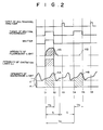
- the timing controller 130 stores in advance the length TS of the measurement time of each of the illuminated measurement and the unilluminated measurement. Based on the above timing difference value TK and the length TS of measurement time, the timing controller 130 outputs the start control signals and the stop control signals of the illuminated measurement and the unilluminated measurement to the spectrometer 50, the multichannel analyzer 140, and the shutter 30, as illustrated in Fig. 2. Thus, the illuminated measurement and the unilluminated measurement are performed in accordance with the start control signals and the stop control signals.
- the shutter 30 is opened, and the specimen 10 is illuminated by the excitation light La.
- the specimen 10 In response to the illumination by the excitation light La, the specimen 10 emits fluorescent light.
- the spectrometer 50 starts the measurement.
- the fluorescent light KA emitted by the specimen 10 and the background light HA passed through the optical condenser system 40 are spectrally dispersed by the spectrally-dispersing portion 51, and the photometric portion 52 measures the intensities of the spectral components of the spectrally-dispersed light.
- time t2 i.e., when time TS has elapsed after time t1, the illuminated measurement is stopped.
- the spectrometer 50 stops the measurement, and holds the measured intensities of the spectral components. Also the shutter 30 is closed to stop the illumination of the specimen 10 by the excitation light La.
- the above intensities obtained by the illuminated measurement which indicate a sum of spectra of the background light HA and the fluorescent light KA, are supplied to and stored in the multichannel analyzer 140 at time t3.
- the unilluminated measurement is started. That is, the spectrometer 50 starts the measurement of the intensities of the spectral components of the spectrally dispersed light. During the unilluminated measurement, the shutter 30 is closed. Since the specimen 10 is not illuminated by the excitation light La, the intensities KB of the fluorescent light is zero, and the spectrometer 50 measures the intensities of the background light HB only.
- the unilluminated measurement is stopped. That is, the spectrometer 50 stops the measurement, and holds the measured intensities of the spectral components.
- the intensities obtained by the unilluminated measurement are supplied to and stored in the multichannel analyzer 140 at time t6.
- the multichannel analyzer 140 subtracts the intensity values indicating the spectral distribution HB obtained by the unilluminated measurement from the intensity values indicating the spectral distribution obtained by the illuminated measurement to obtain the spectral distribution of the fluorescent light KA, and supplies the calculation result to the display device 150.
- Fig. 3A shows a spectral distribution obtained by the illuminated measurement
- Fig. 3B shows a spectral distribution obtained by the unilluminated measurement
- Fig. 3C shows a spectral distribution obtained by subtracting the spectral distribution of Fig. 3B from the spectral distribution of Fig. 3A.
- the contribution SHA of the background light to the spectral distribution of the illuminated measurement illustrated in Fig. 3A is considered to be substantially identical to the spectral distribution SHB of the unilluminated measurement illustrated in Fig. 3B. Therefore, the spectral distribution SKA of the fluorescent light included in the illuminated measurement (as illustrated in Fig. 3C) can be obtained by subtracting the spectral distribution of Fig. 3B from the spectral distribution of Fig. 3A.
- the spectral distribution SKA of the fluorescent light obtained as above is displayed as an image by the display device 150.
- a spectrum of the light to be measured can be measured with high accuracy even when the wavelength range of the background light overlaps the wavelength range of the light to be measured, which has been emitted from a specimen in response to illumination of the specimen, or has been reflected by or has penetrated through a specimen when the specimen is illuminated.
- Fig. 4 shows an outline of the construction of an apparatus for measuring a spectrum of fluorescent light, as the second embodiment of the present invention.
- the apparatus of Fig. 4 executes the method according to the third aspect of the present invention, and therefore realizes the apparatus according to the fourth aspect of the present invention.
- the controller 200 in the construction of Fig. 4 contains a period calculation unit 110, a measurement-time calculation unit 220, a timing controller 230, a multichannel analyzer 140, and a display device 150.
- the period calculation unit 110 receives the intensity values measured by the optical intensity measurement device 60, which indicate the variation of the intensity of the background light, and obtains the value S indicating the period of the variation by calculation.
- the measurement-time calculation unit 220 receives the period value S obtained by the period calculation unit 110, and obtains a common measurement time length value TSS for the illuminated measurement and the unilluminated measurement by multiplying the period value S by an integer, which is stored in advance in the measurement-time calculation unit 220.
- the obtained measurement time length value TSS is supplied to the timing controller 230.
- the timing controller 230 controls the timing of the illuminated measurement and the unilluminated measurement by outputting start control signals and stop control signals for the illuminated measurement and the unilluminated measurement to the spectrometer 50, the multichannel analyzer 140, and the shutter 30 based on the above measurement time length value TSS and a measurement time interval value TKK.
- the measurement time interval value TKK is stored in advance in the timing controller 230, and indicates a time interval between the end of the illuminated measurement and the start of the unilluminated measurement.
- the timing controller 230 further outputs timing control signals to the multichannel analyzer 140.
- the multichannel analyzer 140 receives from the spectrometer 50 intensity values indicating spectral distributions obtained by the illuminated measurement and the unilluminated measurement, based on the above timing control signals, and stores therein the received intensity values indicating spectral distributions. Further, the multichannel analyzer 140 subtracts the intensity values indicating the spectral distribution of the unilluminated measurement from the intensity values indicating the spectral distribution of the illuminated measurement, and supplies the subtraction result to the display device 150.
- the mercury vapor lamp 21 is constantly emitting light, and the excitation light La passed through the band-pass filter 22 contains an emission line called as H line, having a center wavelength of 405 nm.
- the shutter 30 is closed, and therefore the excitation light La is stopped by the shutter 30.
- the optical intensity measurement device 60 performs the measurement of the intensity of the light and supplies the measurement result to the controller 200, before the measurement of the spectral distribution.
- the timing controller 230 stores the measurement time length value TSS as the measurement time length of each of the illuminated measurement and the unilluminated measurement. Thus, the set-up operation of the measurement time length value TSS is completed.
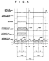
- the timing controller 230 Based on the above measurement time length value TSS and the measurement time interval value TKK between the end of the illuminated measurement and the start of the unilluminated measurement, the timing controller 230 outputs the start control signals and the stop control signals for the illuminated measurement and the unilluminated measurement to the spectrometer 50, the multichannel analyzer 140, and the shutter 30, as illustrated in Fig. 5.
- the illuminated measurement and the unilluminated measurement are performed in accordance with the start control signals and the stop control signals.
- the shutter 30 is opened, and the specimen 10 is illuminated by the excitation light La.
- the specimen 10 In response to the illumination by the excitation light La, the specimen 10 emits fluorescent light.
- the spectrometer 50 starts the measurement.
- the fluorescent light KAA emitted by the specimen 10 and the background light HAA passed through the optical condenser system 40 are spectrally dispersed by the spectrally-dispersing portion 51, and the photometric portion 52 measures the intensities of the spectral components of the spectrally-dispersed light.
- the illuminated measurement is stopped. That is, at time t2', the spectrometer 50 stops the measurement, and holds the measured intensities of the spectral components. Also, the shutter 30 is closed to stop the illumination of the specimen 10 by the excitation light La.
- the above intensities obtained by the illuminated measurement which indicate a sum of spectra of the background light HAA and the fluorescent light KAA, are supplied to and stored in the multichannel analyzer 140 at time t3'.
- the unilluminated measurement is started. That is, the spectrometer 50 starts the measurement of the intensities of the spectral components of the spectrally dispersed light. During the unilluminated measurement, the shutter 30 is closed. Since the specimen 10 is not illuminated by the excitation light La, the intensities KBB of the fluorescent light are zero, and the spectrometer 50 measures the intensities of the background light HBB only.
- time t5' i.e., when time TSS has elapsed after time t4', the unilluminated measurement is stopped.
- the spectrometer 50 stops the measurement, and holds the measured intensities of the spectral components.
- the intensities obtained by the unilluminated measurement i.e., the intensities of the background light HBB, are supplied to and stored in the multichannel analyzer 140 at time t6'.
- the multichannel analyzer 140 subtracts the intensity values indicating the spectral distribution HBB of the unilluminated measurement from the intensity values indicating the spectral distribution of the illuminated measurement to obtain the spectral distribution of the fluorescent light KAA, and supplies the calculation result to the display device 150.
- the lengths of the measurement times of the illuminated measurement and the unilluminated measurement are the same, and the identical length of measurement time equals an integer multiple of the period of the variation of the intensity of the background light. Therefore, the contribution HAA of the background light in the spectral distribution of the illuminated measurement illustrated in Fig. 5 is considered to be substantially identical to the spectral distribution HBB of the unilluminated measurement illustrated in Fig. 5. Therefore, the spectral distribution KAA of the fluorescent light included in the illuminated measurement can be obtained by subtracting the spectral distribution HBB obtained by the unilluminated measurement from the spectral distribution obtained by the illuminated measurement.
- the spectral distribution KAA of the fluorescent light obtained as above is then displayed as an image by the display device 150.
- a spectrum of the light to be measured can be measured with high accuracy even when the wavelength range of the background light overlaps the wavelength range of the light to be measured, which has been emitted from a specimen in response to illumination of the specimen, or has been reflected by or has penetrated through a specimen when the specimen is illuminated.
- Fig. 6 is a diagram illustrating an outline of a construction of an apparatus for measuring a spectrum of fluorescent light, which can be commonly used in the third, fourth, fifth, sixth, and seventh embodiments of the present invention.
- the methods according to the third, fifth, and seventh aspects of the present invention can be executed, and therefore the construction of Fig. 6 can realize the image processing apparatuses according to the sixth, eighth, and tenth aspects of the present invention, as explained below.
- the optical measurement apparatus of Fig. 6 contains a light source 320, a measurement unit 330, a control unit 400, and an display unit 350.
- the light source 320 emits excitation light Le for illuminating a specimen 310, where the excitation light Le has wavelengths in the vicinity of 410 nm.
- the measurement unit 330 detects a spectral distribution of light, and outputs values of the detected spectral distribution, where the detected light includes fluorescent light Ke which is emitted from the specimen 310 in response to the illumination of the excitation light Le.
- the spectral distribution of light is a distribution of intensities of spectral components of light, for example, as illustrated in Fig. 7.
- the control unit 400 controls timing of the measurement based on periods of intensity variations of background light which is included in and should be eliminated from the detected spectral distribution, and data of the periods of intensity variations of background light are input from outside. In addition, the control unit 400 eliminates, by calculation, influence of the background light from the values of the spectral distribution output from the measurement unit 330, and outputs a result of the calculation.
- the display unit 350 displays the result of the calculation output from the 400.
- an excitation-light cut filter 333 is provided, and an optical system 332 and a spectrophotometer 331 are arranged along the optical axis of the measurement unit 330.
- the optical system 332 condenses the fluorescent light Ke emitted from the specimen 310, and the spectrophotometer 331 detects the spectral distribution of the fluorescent light Ke condensed by the optical system 332, by spectrophotometry, and supplies the detected spectral distribution to the control unit 400.
- the control unit 400 contains a measurement condition setting unit 420, a timing controller 430, and a calculation processing unit 440.
- the measurement condition setting unit 420 sets a measurement condition based on the data of the periods of intensity variations of background light which are input from outside.
- the measurement condition setting unit 420 sets in the timing controller 430 a condition on the measurement timing.
- the timing controller 430 generates control signals for starting and stopping the illumination of the excitation light Le and other control signals for starting and stopping the operation of the spectrophotometer 331, based on the measurement condition set by the measurement condition setting unit 420, and outputs the control signals to the light source 320 and the spectrophotometer 331.
- the calculation processing unit 440 processes the values of the spectral distribution supplied from the spectrophotometer 331 by calculation, and outputs the result of the processing to the display unit 350.
- the data Da of the periods of the intensity variation of the background light which is to be eliminated are input from outside through the connector 410 to the measurement condition setting unit 420.
- the data Da include the periods of intensity variations of two types of background light, respectively caused by room illumination, and other illumination which is provided for observing the specimen 310.
- the values of the periods are obtained in advance by measurement, for example, by using another measurement apparatus.
- the measurement condition setting unit 420 determines values of durations of measurement, a time difference between the illuminated measurement and the unilluminated measurement, and a duration of the illumination of the excitation light Le based on the data Da of the periods, obtains timing of the illumination of the excitation light Le, the illuminated measurement, and the unilluminated measurement based on the determined values, and supplies information on the obtained timing to the timing controller 430.
- the specimen 310 is illuminated by the excitation light Le in the illuminated measurement, and the specimen 310 is not illuminated by the excitation light Le in the unilluminated measurement.
- the timing controller 430 When the timing controller 430 receives information on the timing of the illumination of the excitation light Le, the illuminated measurement, and the unilluminated measurement, the timing controller 430 outputs to the light source 320 and the measurement unit 330 the control signals for starting and stopping the illumination of the excitation light Le and starting and stopping the operation of the spectrophotometer 331. Thus, the illuminated measurement and the unilluminated measurement can be performed.
- the spectrophotometer 331 detects the fluorescent light Ke and the two types of background light as a spectral distribution in the illuminated measurement.
- the fluorescent light Ke is not emitted from the specimen 310, and only the aforementioned two types of background light enter the spectrophotometer 331. Therefore, the spectrophotometer 331 detects only the two types of background light as a spectral distribution in the unilluminated measurement.
- the above spectral distributions in the illuminated measurement and the unilluminated measurement are supplied to the calculation processing unit 440, and the influence of the background light is eliminated from the spectral distribution in the illuminated measurement by calculation.
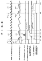
- Fig. 8 is a timing chart of the operations in the third embodiment, which realizes the fifth and sixth aspects of the present invention.
- the above-mentioned two types of background light is room illumination Fa(t) and RGB illumination Fb(t).
- the period fa of the intensity variation of the room illumination Fa(t) is 0.02 sec (i.e., the frequency is 50 Hz).
- the RGB illumination Fb(t) includes red, green, and blue illumination for a field sequential image pick up system, and the period fb of the intensity variation of the RGB illumination Fb(t) is 0.05 sec (i.e., the frequency is 20 Hz).
- the measurement condition setting unit 420 determines values of durations of illuminated measurement and unilluminated measurement, a time difference between the illuminated measurement and the unilluminated measurement, and a duration of the illumination of the excitation light Le based on the data Da of the periods fa and fb, and obtains timing of the illumination of the excitation light Le, the illuminated measurement, and the unilluminated measurement based on the determined values.
- the time difference T1k between the illuminated measurement and the unilluminated measurement is set to be an integer multiple of the least common multiple of the above periods fa and fb of the intensity variations of the room illumination Fa(t) and the RGB illumination Fb(t).
- the duration T1j of each of the illuminated measurement and the unilluminated measurement is determined to be 0.07 sec, which is shorter than the above time difference T1k.
- the duration T1r of the illumination of the excitation light Le is determined to be 0.02 sec, which is shorter than the duration T1j of the illuminated measurement.
- timing t11, t14 of the illuminated measurement timing t12, t13 of the illumination of the excitation light Le, and timing t15, t16 of the unilluminated measurement are obtained.
- the information on the timing t11 to t16 is supplied from the measurement condition setting unit 420 to the timing controller 430, and is then converted into the aforementioned control signals for controlling the light source 320 and the measurement unit 330.
- the control signals are supplied to the light source 320 and the measurement unit 330, the following operations are performed.
- the spectrophotometer 331 detects a spectrum of light which enters the spectrophotometer 331 through the optical system 332, as a spectral distribution SP1c in the illuminated measurement. While the illuminated measurement is performed for the duration T1j of 0.07 sec continuing from time t11 to time t14, the specimen 310 is illuminated with the excitation light Le for the duration T1r of 0.02 sec continuing from time t12 to time t13. In response to the illumination of the excitation light Le, the fluorescent light Ke is emitted from the specimen 310. The fluorescent light Ke enters the spectrophotometer 331, and is detected by the spectrophotometer 331. Although the excitation light Le is reflected by the specimen 310, the reflected excitation light Le is shut off by the excitation-light cut filter 333 so that the reflected excitation light Le is not detected by spectrophotometer 331.
- the unilluminated measurement is commenced at time t15, which is 0.2 sec (the time difference T1k) after time t11.
- the spectrophotometer 331 detects a spectrum of light which enters the spectrophotometer 331 through the optical system 332, to obtain a spectral distribution SP1s in the unilluminated measurement. While the unilluminated measurement is performed for the duration T1j of 0.07 sec continuing from time t15 to time t16, the specimen 310 is not illuminated with the excitation light Le. Therefore, no fluorescent light Ke is detected by the spectrophotometer 331 in the unilluminated measurement.
- the values of the spectral distribution SP1c in the illuminated measurement and the spectral distribution SP1s in the unilluminated measurement are transferred from the spectrophotometer 331 to the calculation processing unit 440.
- the calculation processing unit 440 subtracts the values of the spectral distribution SP1s in the unilluminated measurement from the values of the spectral distribution SP1c in the illuminated measurement, to obtain a spectral distribution SP1k which includes a true spectral distribution of the fluorescent light Ke and does not include influence of the background light, and the spectral distribution SP1k is displayed by the display unit 350.
- the time difference T1k between the illuminated measurement and the unilluminated measurement is equal to twice the least common multiple of the above periods fa and fb of the intensity variations of the room illumination Fa(t) and the RGB illumination Fb(t)
- the time difference T1k is ten times the period fa, and is also four times the period fb.
- the phase P1a1 of the cyclic variation of the room illumination Fa(t) at time t11 at which the illuminated measurement is commenced is identical with the phase P1a2 of the cyclic variation of the room illumination Fa(t) at time t15 at which the unilluminated measurement is commenced
- the phase P1b1 of the cyclic variation of the RGB illumination Fb(t) at time t11 at which the illuminated measurement is commenced is identical with the phase P1b2 of the cyclic variation of the RGB illumination Fb(t) at time t15 at which the unilluminated measurement is commenced.
- the quantity A11 of the room illumination Fa(t) detected in the illuminated measurement and the quantity A12 of the room illumination Fa(t) detected in the unilluminated measurement are identical, and the quantity B11 of the RGB illumination Fb(t) detected in the illuminated measurement and the quantity B12 of the RGB illumination Fb(t) detected in the unilluminated measurement are also identical.
- a spectral distribution SP1a1 of the room illumination Fa(t) detected in the illuminated measurement and a spectral distribution SP1a2 of the room illumination Fa(t) detected in the unilluminated measurement are identical, and a spectral distribution SP1b1 of the RGB illumination Fb(t) detected in the illuminated measurement and a spectral distribution SP1b2 of the RGB illumination Fb(t) detected in the unilluminated measurement are also identical.
- the specimen 310 is illuminated with the excitation light Le for the duration T1r of 0.02 sec during the illuminated measurement, and the fluorescent light Ke is emitted from the specimen 310 in response to the illumination of the excitation light Le. Therefore, a quantity C1 of the fluorescent light Ke having a spectral distribution SP1k is desired to be detected by the spectrophotometer 331.
- the spectral distribution SP1c actually detected by the spectrophotometer 331 in the illuminated measurement is a sum of the spectral distribution SP1k of the fluorescent light Ke, the above-mentioned spectral distribution SP1a1 of the room illumination Fa(t), and the spectral distribution SP1b1 of the RGB illumination Fb(t).
- the aforementioned spectral distribution SP1k which is a true spectral distribution of the fluorescent light Ke and does not include the above spectral distribution SP1a1 of the room illumination Fa(t) and the spectral distribution SP1b1 of the RGB illumination Fb(t), can be obtained by subtracting the spectral distribution SP1a2 of the room illumination Fa(t) and the spectral distribution SP1b2 of the RGB illumination Fb(t) from the spectral distribution SP1c which is actually detected by the spectrophotometer 331 in the illuminated measurement.
- SP1a1 SP1a2
- SP1b1 SP1b2
- Fig. 9 is a timing chart of the operations in the fourth embodiment, which realizes the seventh and eighth aspects of the present invention.
- the measurement condition setting unit 420 determines values of durations of illuminated measurement and unilluminated measurement, a time difference between the illuminated measurement and the unilluminated measurement, and a duration of the illumination of the excitation light Le based on the data Da of the periods fa and fb, and obtains timing of the illumination of the excitation light Le, the illuminated measurement, and the unilluminated measurement based on the determined values.
- the duration T2j of each of the illuminated measurement and the unilluminated measurement is set to be an integer multiple of the least common multiple of the above periods fa and fb.
- the time difference T2k between the illuminated measurement and the unilluminated measurement is determined to be 0.17 sec, which is longer than the above duration T2j
- the duration T2r of the illumination of the excitation light Le is determined to be 0.02 sec, which is shorter than the duration T2j of the illuminated measurement.
- timing t21, t24 of the illuminated measurement timing t22, t23 of the illumination of the excitation light Le, and timing t25, t26 of the unilluminated measurement are obtained.
- the information on the timing t21 to t26 is supplied from the measurement condition setting unit 420 to the timing controller 430, and is then converted into the aforementioned control signals for controlling the light source 320 and the measurement unit 330.
- the control signals are supplied to the light source 320 and the measurement unit 330, the following operations are performed.
- the spectrophotometer 331 detects a spectrum of light which enters the spectrophotometer 331 through the optical system 332, as a spectral distribution SP2c in the illuminated measurement. While the illuminated measurement is performed for the duration T2j of 0.1 sec continuing from time t21 to time t24, the specimen 310 is illuminated with the excitation light Le for the duration T2r of 0.02 sec continuing from time t22 to time t23. In response to the illumination of the excitation light Le, the fluorescent light Ke is emitted from the specimen 310. The fluorescent light Ke enters the spectrophotometer 331, and is detected by the spectrophotometer 331.
- the illuminated measurement is completed at time t24. Then, at time t25, which is 0.17 sec (the time difference T2k) after time t21, the unilluminated measurement is commenced.
- the spectrophotometer 331 detects a spectrum of light which enters the spectrophotometer 331 through the optical system 332, as a spectral distribution SP2s in the unilluminated measurement. While the unilluminated measurement is performed for the duration T2j of 0.1 sec continuing from time t25 to time t26, the specimen 310 is not illuminated with the excitation light Le. Therefore, no fluorescent light Ke is detected by the spectrophotometer 331 in the unilluminated measurement.
- the values of the spectral distribution SP2c in the illuminated measurement and the spectral distribution SP2s in the unilluminated measurement are transferred from the spectrophotometer 331 to the calculation processing unit 440.
- the calculation processing unit 440 subtracts the values of the spectral distribution SP2s in the unilluminated measurement from the values of the spectral distribution SP2c in the illuminated measurement to obtain a spectral distribution SP2k, which shows a true spectral distribution of the fluorescent light Ke and does not include influence of the background light.
- the spectral distribution SP2k is displayed by the display unit 350.
- the duration T2j of each of the illuminated measurement and the unilluminated measurement is equal to the least common multiple of the above periods fa and fb, the duration T2j is five times the period fa, and is also twice the period fb. Therefore, regardless of the phases of the background light at the beginning times of the illuminated measurement and the unilluminated measurement, in each of the illuminated measurement and the unilluminated measurement, measurement of light is concurrently performed for five periods of the cyclic variation of the room illumination Fa(t) and for two periods of the cyclic variation of the RGB illumination Fb(t).
- the quantity A21 of the room illumination Fa(t) detected in the illuminated measurement is identical with the quantity A22 of the room illumination Fa(t) detected in the unilluminated measurement
- the spectral distribution SP2a1 of the room illumination Fa(t) detected in the illuminated measurement is identical with the spectral distribution SP2a2 of the room illumination Fa(t) detected in the unilluminated measurement.
- the quantity of light B21 of the RGB illumination Fb(t) detected in the illuminated measurement is identical with the quantity of light B22 of the RGB illumination Fb(t) detected in the unilluminated measurement
- the spectral distribution SP2b1 of the RGB illumination Fb(t) detected in the illuminated measurement is identical with the spectral distribution SP2b2 of the RGB illumination Fb(t) detected in the unilluminated measurement.
- the specimen 310 is illuminated with the excitation light Le for the duration T2r of 0.02 sec during the illuminated measurement, and the fluorescent light Ke is emitted from the specimen 310 in response to the illumination of the excitation light Le. Therefore, a quantity C2 of the fluorescent light Ke having the spectral distribution SP2k is desired to be detected by the spectrophotometer 331.
- the spectral distribution SP2c actually detected by the spectrophotometer 331 in the illuminated measurement is a sum of the spectral distribution SP2k of the fluorescent light Ke, the above-mentioned spectral distribution SP2a1 of the room illumination Fa(t), and the spectral distribution SP2b1 of the RGB illumination Fb(t).
- the aforementioned spectral distribution SP2k which shows a true spectral distribution of the fluorescent light Ke and does not include the above spectral distribution SP2a1 of the room illumination Fa(t) and the spectral distribution SP2b1 of the RGB illumination Fb(t), can be obtained by subtracting the spectral distribution SP2a2 of the room illumination Fa(t) and the spectral distribution SP2b2 of the RGB illumination Fb(t) from the spectral distribution SP2c which is actually detected by the spectrophotometer 331 in the illuminated measurement.
- SP2a1 SP2a2
- SP2b1 SP2b2
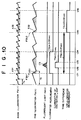
- Fig. 10 is a timing chart of the operations in the fifth embodiment, which realizes the ninth and tenth aspects of the present invention.
- the measurement condition setting unit 420 determines values of durations of illuminated measurement and unilluminated measurement, a time difference between the illuminated measurement and the unilluminated measurement, and a duration of the illumination of the excitation light Le based on the data Da of the periods fa and fb, and obtains timing of the illumination of the excitation light Le, the illuminated measurement, and the unilluminated measurement based on the determined values.
- the illuminated measurement and the unilluminated measurement are performed for the same duration T3j, and the duration T3j is equal to an integer multiple of one of the periods fa and fb, and the time difference T3k between the beginning times of the illuminated measurement and the unilluminated measurement is an integer multiple of the other of the periods fa and fb.
- the time difference T3k between the illuminated measurement and the unilluminated measurement is determined to be 0.15 sec, which is three times the period fb
- the duration T3j of each of the illuminated measurement and the unilluminated measurement is determined to be 0.08 sec, which is four times the period fa.
- the duration T3r of the illumination of the excitation light Le is determined to be 0.02 sec, which is shorter than the duration T3j of the illuminated measurement.
- timing t31, t34 of the illuminated measurement timing t32, t33 of the illumination of the excitation light Le, and timing t35, t36 of the unilluminated measurement are obtained.
- the information on the timing t31 to t36 is supplied from the measurement condition setting unit 420 to the timing controller 430, and is then converted into the aforementioned control signals for controlling the light source 320 and the measurement unit 330.
- the control signals are supplied to the light source 320 and the measurement unit 330, the following operations are performed.
- the spectrophotometer 331 detects a spectrum of light which enters the spectrophotometer 331 through the optical system 332, as a spectral distribution SP2c in the illuminated measurement. While the illuminated measurement is performed for the duration T3j of 0.1 sec continuing from time t31 to time t34, the specimen 310 is illuminated with the excitation light Le for the duration T3r of 0.02 sec continuing from time t32 to time t33. In response to the illumination of the excitation light Le, the fluorescent light Ke is emitted from the specimen 310. The fluorescent light Ke enters the spectrophotometer 331, and is detected by the spectrophotometer 331.
- the illuminated measurement is completed at time t34. Then, at time t35, which is 0.15 sec (the time difference T3k) after time t31, the unilluminated measurement is commenced.
- the spectrophotometer 331 detects a spectrum of light which enters the spectrophotometer 331 through the optical system 332, as a spectral distribution SP3s in the unilluminated measurement. While the unilluminated measurement is performed for the duration T3j of 0.08 sec continuing from time t35 to time t36, the specimen 310 is not illuminated with the excitation light Le. Therefore, no fluorescent light Ke is detected by the spectrophotometer 331 in the unilluminated measurement.
- the values of the spectral distribution SP3c in the illuminated measurement and the spectral distribution SP3s in the unilluminated measurement are transferred from the spectrophotometer 331 to the calculation processing unit 440.
- the calculation processing unit 440 subtracts the values of the spectral distribution SP3s in the unilluminated measurement from the values of the spectral distribution SP3c in the illuminated measurement to obtain a spectral distribution SP3k, which shows a true spectral distribution of the fluorescent light Ke and does not include influence of the background light.
- the spectral distribution SP3k is displayed by the display unit 350.
- the duration T3j of each of the illuminated measurement and the unilluminated measurement is four times the above period fa of the intensity variations of the room illumination Fa(t). Therefore, regardless of the phases of the room illumination Fa(t) at the beginning times of the illuminated measurement and the unilluminated measurement, measurement of light is performed for four periods of the cyclic variation of the room illumination Fa(t) in each of the illuminated measurement and the unilluminated measurement.
- the quantity A31 of the room illumination Fa(t) detected in the illuminated measurement is identical with the quantity A32 of the room illumination Fa(t) detected in the unilluminated measurement
- the spectral distribution SP3a1 of the room illumination Fa(t) detected in the illuminated measurement is identical with the spectral distribution SP3a2 of the room illumination Fa(t) detected in the unilluminated measurement.
- the time difference T3k between the illuminated measurement and the unilluminated measurement is three times the period fb of the RGB illumination Fb(t)
- the phase P3b1 of the RGB illumination Fb(t) at time t31 at which the illuminated measurement is commenced is identical with the phase P3b2 of the RGB illumination Fb(t) at time t35 at which the unilluminated measurement is commenced.
- the quantity B31 of the RGB illumination Fb(t) detected in the illuminated measurement and the quantity B32 of the RGB illumination Fb(t) detected in the unilluminated measurement are identical, and the spectral distribution SP3b1 of the RGB illumination Fb(t) detected in the illuminated measurement and the spectral distribution SP3b2 of the RGB illumination Fb(t) detected in the unilluminated measurement are also identical.
- the specimen 310 is illuminated with the excitation light Le for the duration T3r of 0.02 sec during the illuminated measurement, and fluorescent light Ke is emitted from the specimen 310 in response to the illumination of the excitation light Le. Therefore, a quantity C3 of the fluorescent light Ke having a spectral distribution SP3k is desired to be detected by the spectrophotometer 331.
- a spectral distribution SP3c actually detected by the spectrophotometer 331 in the illuminated measurement is a sum of the spectral distribution of the fluorescent light Ke, the above-mentioned spectral distribution SP3a1 of the room illumination Fa(t) and the spectral distribution SP3b1 of the RGB illumination Fb(t).
- the aforementioned spectral distribution SP3k which shows a true spectral distribution of the fluorescent light Ke and does not include the above spectral distribution SP3a1 of the room illumination Fa(t) and the spectral distribution SP3b1 of the RGB illumination Fb(t), can be obtained by subtracting the spectral distribution SP3a2 of the room illumination Fa(t) and the spectral distribution SP3b2 of the RGB illumination Fb(t) from the spectral distribution SP3c actually detected by the spectrophotometer 331 in the illuminated measurement.
- SP3a1 SP3a2
- SP3b1 SP3b2
- Fig. 11 is a timing chart of the operations in the sixth embodiment, which realizes the ninth and tenth aspects of the present invention.
- the sixth embodiment two sets of illuminated measurement and unilluminated measurement are performed, and the operations in each set are similar to the operations in the fifth embodiment.
- the timing controller 420 determines values of durations of illuminated measurement and unilluminated measurement, a time difference between the illuminated measurement and the unilluminated measurement, and a duration of the illumination of the excitation light Le based on the data Da of the periods fa and fb, and obtains, for each set, timing of the illumination of the excitation light Le, illuminated measurement, and unilluminated measurement based on the determined values.
- the time difference T4k between the illuminated measurement and the unilluminated measurement in each set is determined to be 0.15 sec, which is three times the period fb, and the duration T4j of each of the illuminated measurement and the unilluminated measurement is determined to be 0.02 sec, which is identical with the period fa.
- the duration T4r of the illumination of the excitation light Le is determined to be 0.01 sec, which is shorter than the duration T4j of the illuminated measurement.
- the measurement condition setting unit 420 obtains the timing t41, t44 of the illuminated measurement, timing t42, t43 of the illumination of the excitation light Le, and timing t45, t46 of the unilluminated measurement for the first set of operations, and timing t41', t44' of the illuminated measurement, timing t42', t43' of the illumination of the excitation light Le, and timing t45', t46' of the unilluminated measurement for the second set of operations.
- the information on the timing t41 to t46, and t41' to t46' is supplied from the measurement condition setting unit 420 to the timing controller 430, and is then converted into the aforementioned control signals for controlling the light source 320 and the measurement unit 330.
- the control signals are supplied to the light source 320 and the measurement unit 330, the following operations are performed.
- the illuminated measurement is performed for the duration T4j of 0.02 sec continuing from time t41 to t44, and the specimen 310 is illuminated with the excitation light Le for the duration T4r of 0.01 sec continuing from time t42 to time t43 during the illuminated measurement.
- a spectral distribution SP4c which includes a spectral distribution of fluorescent light Ke emitted in response to the illumination of the excitation light Le, a spectral distribution of the room illumination Fa(t), and a spectral distribution of the RGB illumination Fb(t), is detected by the measurement unit 330.
- the unilluminated measurement is performed for the duration T4j of 0.02 sec continuing from time t45 to t46, and thus a spectral distribution SP4s, which includes a spectral distribution of the room illumination Fa(t), and a spectral distribution of the RGB illumination Fb(t), is detected by the measurement unit 330.
- the illuminated measurement is performed for the duration T4j of 0.02 sec continuing from time t41' to t44', and the specimen 310 is illuminated with the excitation light Le for the duration T4r of 0.01 sec continuing from time t42' to time t43' during the illuminated measurement.
- a spectral distribution SP4c' which includes a spectral distribution of fluorescent light Ke emitted in response to the illumination of the excitation light Le, a spectral distribution of the room illumination Fa(t), and a spectral distribution of the RGB illumination Fb(t), is detected by the measurement unit 330.
- the unilluminated measurement is performed for the duration T4j of 0.02 sec continuing from time t45' to t46', and thus a spectral distribution SP4s', which includes a spectral distribution of the room illumination Fa(t) and a spectral distribution of the RGB illumination Fb(t), is detected by the measurement unit 330.
- the first set of operations it is possible to obtain a true spectral distribution SP4k of the fluorescent light Ke which does not include the above spectral distribution of the room illumination Fa(t) and the spectral distributions of the RGB illumination Fb(t), by subtracting the spectral distributions SP4s from the spectral distribution SP4c.
- the second set of operations it is possible to obtain another true spectral distribution SP4k' of the fluorescent light Ke which does not include the above spectral distribution of the room illumination Fa(t) and the spectral distributions of the RGB illumination Fb(t), by subtracting the spectral distributions SP4s' and the spectral distribution SP4c'.
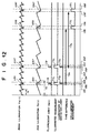
- Fig. 12 is a timing chart of the operations in the seventh embodiment, which realizes the fifth and sixth aspects of the present invention.
- the seventh embodiment two sets of illuminated measurement and unilluminated measurement are performed, and the operations in each set are similar to the operations in the third embodiment.
- the timing controller 420 determines values of durations of illuminated measurement and unilluminated measurement, a time difference between the illuminated measurement and the unilluminated measurement, and a duration of the illumination of the excitation light Le based on the data Da of the periods fa and fb, and obtains, for each set, timing of the illumination of the excitation light Le, illuminated measurement, and unilluminated measurement based on the determined values.
- the time difference T5k between the illuminated measurement and the unilluminated measurement in each set is determined to be equal to an integer multiple of the least common multiple of the periods fa and fb.
- the duration T5j of each of the illuminated measurement and the unilluminated measurement is determined to be 0.01 sec, which is shorter than the above time difference T5k
- the duration T5r of the illumination of the excitation light Le is determined to be 0.005 sec, which is shorter than the duration T5j.
- the measurement condition setting unit 420 obtains timing t51, t54 of the illuminated measurement, timing t52, t53 of the illumination of the excitation light Le, and timing t55, t56 of the unilluminated measurement for the first set of operations, and timing t51', t54' of the illuminated measurement, timing t52', t53' of the illumination of the excitation light Le, and timing t55', t56' of the unilluminated measurement for the second set of operations.
- the information on the timing t51 to t56, and t51' to t56' is supplied from the measurement condition setting unit 420 to the timing controller 430, and is then converted into the aforementioned control signals for controlling the light source 320 and the measurement unit 330.
- the control signals are supplied to the light source 320 and the measurement unit 330, the following operations are performed.
- the illuminated measurement is performed for the duration T5j of 0.01 sec continuing from time t51 to t54, and the specimen 310 is illuminated with the excitation light Le for the duration T5r of 0.01 sec continuing from time t52 to time t53 during the illuminated measurement.
- a spectral distribution SP5c is detected by the measurement unit 330, where the spectral distribution SP5c is a sum of a spectral distribution of fluorescent light Ke emitted in response to the illumination of the excitation light Le, a spectral distribution of the room illumination Fa(t), and a spectral distribution of the RGB illumination Fb(t).
- the unilluminated measurement is performed for the duration T5j of 0.01 sec continuing from time t55 to t56.
- a spectral distribution SP5s is detected by the measurement unit 330, where the spectral distribution SP5s is a sum of a spectral distribution of the room illumination Fa(t), and a spectral distribution of the RGB illumination Fb(t).
- the illuminated measurement is performed for the duration T5j of 0.2 sec continuing from time t51' to t54', and the specimen 310 is illuminated with the excitation light Le for the duration T5r of 0.01 sec continuing from time t52' to time t53' during the illuminated measurement.
- a spectral distribution SP5c' is detected by the measurement unit 330, where the spectral distribution SP5c' is a sum of a spectral distribution of fluorescent light Ke emitted in response to the illumination of the excitation light Le, a spectral distribution of the room illumination Fa(t), and a spectral distribution of the RGB illumination Fb(t).
- the unilluminated measurement is performed for the duration T5j of 0.2 sec continuing from time t55' to t56'.
- a spectral distribution SP5s' is detected by the measurement unit 330, where the spectral distribution SP5s' is a sum of a spectral distribution of the room illumination Fa(t), and a spectral distribution of the RGB illumination Fb(t).
- the timing of the illuminated measurement and the unilluminated measurement is in the vicinity of a certain phase of the cyclic variation of one of the room illumination Fa(t) and the RGB illumination Fb(t) which has a shorter period than the other, where the intensity of that one of the room illumination Fa(t) and the RGB illumination Fb(t) is minimized in the certain phase.
- the period fa of the room illumination Fa(t) is shorter than the period fb of the RGB illumination Fb(t)
- each of the illuminated measurement and the unilluminated measurement is performed for a duration which includes at its center a phase in which the intensity of the room illumination Fa(t) is minimized.
- the influence of the background light can be eliminated further effectively.
- the present invention can be applied to spectrum analyzers, quantitative analyzers, image measurement apparatuses, and the like which perform measurement of fluorescence, phosphorescence, absorption, or the like.
Landscapes
- Health & Medical Sciences (AREA)
- General Health & Medical Sciences (AREA)
- Life Sciences & Earth Sciences (AREA)
- Chemical & Material Sciences (AREA)
- Analytical Chemistry (AREA)
- Biochemistry (AREA)
- Physics & Mathematics (AREA)
- General Physics & Mathematics (AREA)
- Immunology (AREA)
- Pathology (AREA)
- Nuclear Medicine, Radiotherapy & Molecular Imaging (AREA)
- Investigating Or Analysing Materials By Optical Means (AREA)
- Investigating, Analyzing Materials By Fluorescence Or Luminescence (AREA)
Abstract
Description
Claims (30)
- An optical measurement method for performing measurement of first light, which has been emitted from or reflected by a specimen, or has penetrated through the specimen, under background light having intensity which varies cyclically with a period, said method comprising steps of:(a) performing a first operation of measuring the first light for a first duration having a certain length and beginning at a first time, while illuminating the specimen with second light, to obtain a first measurement result;(b) performing a second operation of measuring the first light for a second duration having the same length as the first duration and beginning at a second time which is different from said first time by an integer multiple of said period, while illumination of the specimen is stopped, to obtain a second measurement result; and(c) subtracting said second measurement result from said first measurement result, to obtain a third measurement result which is not affected by said background light.
- An optical measurement method according to claim 1, further comprising an additional step of obtaining said period by measuring the intensity of the background light.
- An optical measurement apparatus for performing measurement of first light, which has been emitted from or reflected by a specimen, or has penetrated through the specimen, under background light having intensity which varies cyclically with a period, said apparatus comprising:a first measurement unit which performs a first operation of measuring the first light while illuminating the specimen with second light, to obtain a first measurement result;a second measurement unit which performs a second operation of measuring the first light while illumination of the specimen is stopped, to obtain a second measurement result;a control unit which controls timing of the operations of the first and second measurement units so that said first operation is performed for a first duration having a certain length and beginning at a first time, and said second operation is performed for a second duration having the same length as the first duration and beginning at a second time which is different from said first time by an integer multiple of said period; anda calculation unit which obtains a third measurement result, which is not affected by said background light, by subtracting said second measurement result from said first measurement result.
- An optical measurement apparatus according to claim 3, further comprising an additional unit which obtains said period by measuring the intensity of the background light.
- An optical measurement method for performing measurement of first light, which has been emitted from or reflected by a specimen, or has penetrated through the specimen, under background light having intensity which varies cyclically with a period, said method comprising steps of:(a) performing a first operation of measuring the first light for a first duration having a length equal to an integer multiple of said period, while illuminating the specimen with second light, to obtain a first measurement result;(b) performing a second operation of measuring the first light for a second duration having a length equal to the length of the first duration, while illumination of the specimen is stopped, to obtain a second measurement result; and(c) subtracting said second measurement result from said first measurement result, to obtain a third measurement result which is not affected by said background light.
- An optical measurement method according to claim 5, further comprising an additional step of obtaining said period by measuring the intensity of the background light.
- An optical measurement apparatus for performing measurement of first light, which has been emitted from or reflected by a specimen, or has penetrated through the specimen, under background light having an intensity which varies cyclically with a period, said apparatus comprising:a first measurement unit which performs a first operation of measuring the first light while illuminating the specimen with second light, to obtain a first measurement result;a second measurement unit which performs a second operation of measuring the first light while illumination of the specimen is stopped, to obtain a second measurement result;a control unit which controls timing of the operations of the first and second measurement units so that each of said first and second operations is performed for a duration having an identical length equal to an integer multiple of said period; anda calculation unit which obtains a third measurement result, which is not affected by said background light, by subtracting said second measurement result from said first measurement result.
- An optical measurement apparatus according to claim 7, further comprising an additional unit which obtains said period by measuring the intensity of the background light.
- An optical measurement method for performing measurement of first light, which has been emitted from or reflected by a specimen, or has penetrated through the specimen, under a plurality of types of background light respectively having a plurality of different periods with which intensities of the plurality of types of background light vary cyclically, said method comprising steps of:(a) performing a first operation of measuring the first light for a first duration having a length equal to an integer multiple of a least common multiple of said plurality of different periods, while illuminating the specimen with second light, to obtain a first measurement result;(b) performing a second operation of measuring the first light for a second duration having a length equal to the length of the first duration, while illumination of the specimen is stopped, to obtain a second measurement result; and(c) subtracting said second measurement result from said first measurement result, to obtain a third measurement result which is not affected by said plurality of types of background light.
- An optical measurement apparatus for performing measurement of first light, which has been emitted from or reflected by a specimen, or has penetrated through the specimen, under a plurality of types of background light respectively having a plurality of different periods with which intensities of the plurality of types of background light vary cyclically, said apparatus comprising:a first measurement unit which performs a first operation of measuring the first light while illuminating the specimen with second light, to obtain a first measurement result;a second measurement unit which performs a second operation of measuring the first light while illumination of the specimen is stopped, to obtain a second measurement result;a control unit which controls timing of the operations of the first and second measurement units so that each of said first and second operations is performed for a duration having an identical length equal to an integer multiple of a least common multiple of said plurality of different periods; anda calculation unit which obtains a third measurement result, which is not affected by said plurality of types of background light, by subtracting said second measurement result from said first measurement result.
- An optical measurement method for performing measurement of first light, which has been emitted from or reflected by a specimen, or has penetrated through the specimen, under a plurality of types of background light respectively having a plurality of different periods with which intensities of the plurality of types of background light vary cyclically, said method comprising steps of:(a) performing a first operation of measuring the first light for a first duration having a certain length and beginning at a first time while illuminating the specimen with second light, to obtain a first measurement result;(b) performing a second operation of measuring the first light for a second duration having the same length as the first duration and beginning at a second time which is different from said first time by an integer multiple of a least common multiple of said plurality of different periods, while illumination of the specimen is stopped, to obtain a second measurement result; and(c) subtracting said second measurement result from said first measurement result, to obtain a third measurement result which is not affected by said plurality of types of background light.
- An optical measurement method according to claim 11, wherein each of said first and second operations is performed a plurality of times.
- An optical measurement method according to claim 11, wherein each of said first and second operations is performed in synchronization with one of the plurality of different periods of a selected one of the plurality of types of background light.
- An optical measurement method according to claim 13, wherein each of said first and second operations is performed in the vicinity of a certain phase of said one of the plurality of different periods, where the intensity of the selected one of the plurality of types of background light is minimized in said certain phase.
- An optical measurement method according to claim 13, wherein said one of the plurality of different periods is a minimum period of the plurality of different periods.
- An optical measurement apparatus for performing measurement of first light, which has been emitted from or reflected by a specimen, or has penetrated through the specimen, under a plurality of types of background light respectively having a plurality of different periods with which intensities of the plurality of types of background light vary cyclically, said apparatus comprising:a first measurement unit which performs a first operation of measuring the first light while illuminating the specimen with second light, to obtain a first measurement result;a second measurement unit which performs a second operation of measuring the first light while illumination of the specimen is stopped, to obtain a second measurement result;a control unit which controls timing of the operations of the first and second measurement units so that said first operation is performed for a first duration having a certain length and beginning at a first time, and said second operation is performed for a second duration having the same length as the first duration and beginning at a second time which is different from said first time by an integer multiple of a least common multiple of said plurality of different periods; anda calculation unit which obtains a third measurement result, which is not affected by said plurality of types of background light, by subtracting said second measurement result from said first measurement result.
- An optical measurement apparatus according to claim 16, wherein each of said first and second operations is performed a plurality of times.
- An optical measurement apparatus according to claim 16, wherein each of said first and second operations is performed in synchronization with one of the plurality of different periods of a selected one of the plurality of types of background light.
- An optical measurement apparatus according to claim 18, wherein each of said first and second operations is performed in the vicinity of a certain phase of said one of the plurality of different periods, where the intensity of the selected one of the plurality of types of background light is minimized in said certain phase.
- An optical measurement apparatus according to claim 18, wherein said one of the plurality of different periods is a minimum period of the plurality of different periods.
- An optical measurement method for performing measurement of first light, which has been emitted from or reflected by a specimen, or has penetrated through the specimen, under a plurality of types of background light respectively having a plurality of different periods with which intensities of the plurality of types of background light vary cyclically, said method comprising steps of:(a) performing a first operation of measuring the first light for a first duration beginning at a first time and having a length equal to an integer multiple of a least common multiple of at least one period among said plurality of different periods, while illuminating the specimen with second light, to obtain a first measurement result;(b) performing a second operation of measuring the first light for a second duration having the same length as the first duration and beginning at a second time which is different from said first time by an integer multiple of a least common multiple of said plurality of different periods other than said at least one period, while illumination of the specimen is stopped, to obtain a second measurement result; and(c) subtracting said second measurement result from said first measurement result, to obtain a third measurement result which is not affected by said plurality of types of background light.
- An optical measurement method according to claim 21, wherein each of said first and second operations is performed a plurality of times.
- An optical measurement method according to claim 21, wherein each of said first and second operations is performed in synchronization with a selected one of said plurality of different periods other than said at least one period.
- An optical measurement method according to claim 23, wherein each of said first and second operations is performed in the vicinity of a certain phase of said selected one of said plurality of different periods other than said at least one period, where the intensity of the selected one of the plurality of types of background light is minimized in said certain phase.
- An optical measurement method according to claim 23, wherein said selected one of said plurality of different periods other than said at least one period is a minimum period of the plurality of different periods other than the at least one period.
- An optical measurement apparatus for performing measurement of first light, which has been emitted from or reflected by a specimen, or has penetrated through the specimen, under a plurality of types of background light respectively having a plurality of different periods with which intensities of the plurality of types of background light vary cyclically, said apparatus comprising:a first measurement unit which performs a first operation of measuring the first light while illuminating the specimen with second light, to obtain a first measurement result;a second measurement unit which performs a second operation of measuring the first light while illumination of the specimen is stopped, to obtain a second measurement result;a control unit which controls timing of the operations of the first and second measurement units so that said first operation is performed for a first duration beginning at a first time and having a length equal to an integer multiple of a least common multiple of at least one period among said plurality of different periods, and said second operation is performed for a second duration having the same length as the first duration and beginning at a second time which is different from said first time by an integer multiple of a least common multiple of said plurality of different periods other than said at least one period; anda calculation unit which obtains a third measurement result, which is not affected by said plurality of types of background light, by subtracting said second measurement result from said first measurement result.
- An optical measurement apparatus according to claim 26, wherein each of said first and second operations is performed a plurality of times.
- An optical measurement apparatus according to claim 26, wherein each of said first and second operations is performed in synchronization with a selected one of said plurality of different periods other than said at least one period.
- An optical measurement apparatus according to claim 28, wherein each of said first and second operations is performed in the vicinity of a certain phase of said selected one of said plurality of different periods other than said at least one period, where the intensity of the selected one of the plurality of types of background light is minimized in said certain phase.
- An optical measurement apparatus according to claim 28, wherein said selected one of said plurality of different periods other than said at least one period is a minimum period of the plurality of different periods other than the at least one period.
Applications Claiming Priority (4)
| Application Number | Priority Date | Filing Date | Title |
|---|---|---|---|
| JP03374199A JP3761734B2 (en) | 1999-02-12 | 1999-02-12 | Optical measurement method and apparatus |
| JP3374199 | 1999-02-12 | ||
| JP23909599 | 1999-08-26 | ||
| JP23909599A JP3727494B2 (en) | 1999-08-26 | 1999-08-26 | Optical measurement method and apparatus |
Publications (3)
| Publication Number | Publication Date |
|---|---|
| EP1035409A2 true EP1035409A2 (en) | 2000-09-13 |
| EP1035409A3 EP1035409A3 (en) | 2002-08-07 |
| EP1035409B1 EP1035409B1 (en) | 2008-07-02 |
Family
ID=26372485
Family Applications (1)
| Application Number | Title | Priority Date | Filing Date |
|---|---|---|---|
| EP00102884A Expired - Lifetime EP1035409B1 (en) | 1999-02-12 | 2000-02-11 | Method and apparatus for measurement of light from illuminated specimen eliminating influence of background light |
Country Status (3)
| Country | Link |
|---|---|
| US (1) | US6597439B1 (en) |
| EP (1) | EP1035409B1 (en) |
| DE (1) | DE60039323D1 (en) |
Cited By (2)
| Publication number | Priority date | Publication date | Assignee | Title |
|---|---|---|---|---|
| WO2011045469A1 (en) * | 2009-10-15 | 2011-04-21 | Valtion Teknillinen Tutkimuskeskus | Measurement of raman radiation |
| WO2017221024A1 (en) * | 2016-06-23 | 2017-12-28 | Inspection Technologies Limited | Apparatus and method for extracting low intensity photonic signals |
Families Citing this family (10)
| Publication number | Priority date | Publication date | Assignee | Title |
|---|---|---|---|---|
| US7116354B2 (en) * | 2001-06-20 | 2006-10-03 | Xenogen Corporation | Absolute intensity determination for a light source in low level light imaging systems |
| US7629573B2 (en) * | 2002-02-06 | 2009-12-08 | Xenogen Corporation | Tissue phantom calibration device for low level light imaging systems |
| US7649185B2 (en) * | 2002-02-06 | 2010-01-19 | Xenogen Corporation | Fluorescent phantom device |
| US20070268481A1 (en) * | 2006-05-17 | 2007-11-22 | Ramesh Raskar | System and method for measuring scene reflectance using optical sensors |
| US20090236541A1 (en) * | 2008-03-24 | 2009-09-24 | General Electric Company | System and Methods for Optical Imaging |
| JP5761946B2 (en) * | 2010-09-02 | 2015-08-12 | キヤノン株式会社 | Image processing apparatus, image processing method, and storage medium |
| JP6501230B2 (en) * | 2016-03-08 | 2019-04-17 | 株式会社リガク | Multi-element simultaneous fluorescent X-ray analyzer and multi-element simultaneous fluorescent X-ray analysis method |
| JP7026337B2 (en) | 2017-08-29 | 2022-02-28 | パナソニックIpマネジメント株式会社 | Optical observation device |
| DE102019204843A1 (en) * | 2018-04-06 | 2019-10-10 | Virtek Vision International Ulc | Detecting fluorescence from foreign material |
| US11345014B2 (en) | 2019-02-15 | 2022-05-31 | Virtek Vision International Inc | Method of detecting proper orientation of material applique |
Family Cites Families (11)
| Publication number | Priority date | Publication date | Assignee | Title |
|---|---|---|---|---|
| US3903422A (en) | 1974-06-14 | 1975-09-02 | Gte Laboratories Inc | Digital fluorometer |
| JPS5510569A (en) * | 1978-07-10 | 1980-01-25 | Minolta Camera Co Ltd | Method and apparatus for photometry |
| JPS58139036A (en) * | 1982-02-15 | 1983-08-18 | Japan Spectroscopic Co | Spectrophotometer |
| US4756884A (en) * | 1985-08-05 | 1988-07-12 | Biotrack, Inc. | Capillary flow device |
| CA1311625C (en) | 1988-09-30 | 1992-12-22 | Claritek Research & Engineering Co. | Turbidity meter |
| US4991971A (en) * | 1989-02-13 | 1991-02-12 | United Technologies Corporation | Fiber optic scatterometer for measuring optical surface roughness |
| US5368224A (en) * | 1992-10-23 | 1994-11-29 | Nellcor Incorporated | Method for reducing ambient noise effects in electronic monitoring instruments |
| JPH07294248A (en) * | 1994-04-28 | 1995-11-10 | Hamamatsu Photonics Kk | Distance measuring equipment |
| CA2229458A1 (en) | 1995-08-22 | 1997-03-06 | Vivorx Pharmaceuticals, Inc. | Method and apparatus for determining characteristics of a sample in the presence of ambient light |
| US5800348A (en) * | 1995-08-31 | 1998-09-01 | Hewlett-Packard Company | Apparatus and method for medical monitoring, in particular pulse oximeter |
| US6122042A (en) * | 1997-02-07 | 2000-09-19 | Wunderman; Irwin | Devices and methods for optically identifying characteristics of material objects |
-
2000
- 2000-02-11 DE DE60039323T patent/DE60039323D1/en not_active Expired - Lifetime
- 2000-02-11 EP EP00102884A patent/EP1035409B1/en not_active Expired - Lifetime
- 2000-02-11 US US09/502,579 patent/US6597439B1/en not_active Expired - Fee Related
Cited By (4)
| Publication number | Priority date | Publication date | Assignee | Title |
|---|---|---|---|---|
| WO2011045469A1 (en) * | 2009-10-15 | 2011-04-21 | Valtion Teknillinen Tutkimuskeskus | Measurement of raman radiation |
| US8917388B2 (en) | 2009-10-15 | 2014-12-23 | Teknologian Tutkimuskeskus Vtt | Measurement of raman radiation |
| WO2017221024A1 (en) * | 2016-06-23 | 2017-12-28 | Inspection Technologies Limited | Apparatus and method for extracting low intensity photonic signals |
| US10761024B2 (en) | 2016-06-23 | 2020-09-01 | Inspection Technologies, Ltd | Apparatus and method for extracting low intensity photonic signals |
Also Published As
| Publication number | Publication date |
|---|---|
| DE60039323D1 (en) | 2008-08-14 |
| EP1035409B1 (en) | 2008-07-02 |
| EP1035409A3 (en) | 2002-08-07 |
| US6597439B1 (en) | 2003-07-22 |
Similar Documents
| Publication | Publication Date | Title |
|---|---|---|
| JP3346095B2 (en) | Spectrophotometer | |
| US9551658B2 (en) | STED microscopy with pulsed excitation, continuous stimulation, and gated registration of spontaneously emitted fluorescence light | |
| EP1035409B1 (en) | Method and apparatus for measurement of light from illuminated specimen eliminating influence of background light | |
| US6300639B1 (en) | Process and arrangement for the device configuration of confocal microscopes | |
| JP5623278B2 (en) | Microscope and operating method of microscope | |
| US6958811B2 (en) | Method for the detection of dyes in fluorescence microscopy | |
| US8288739B2 (en) | Method and apparatus for measuring optical property of fluorescent sample | |
| EP2315004A1 (en) | Spectrometer, spectrometry, and spectrometry program | |
| US11579089B2 (en) | Raman microscope having fluorescence observation function and filter unit | |
| JP3836426B2 (en) | Method and apparatus configuration for optically grasping characteristic characteristic values depending on wavelength of illuminated sample | |
| US7449151B2 (en) | Fluorescence resonance energy transfer analyzer | |
| US7724365B2 (en) | Spectral observation method and spectral observation system | |
| JPH11118603A (en) | Spectral characteristic measuring apparatus of fluorescent specimen and its measuring method | |
| JP2011513740A (en) | Time-resolved spectroscopic analysis method and system using photon mixing detector | |
| JP2019020362A (en) | Spectrofluoro-photometer, and spectrofluorometric measurement and image capturing method | |
| JP3761734B2 (en) | Optical measurement method and apparatus | |
| US9651765B2 (en) | Method for separating detection signals in the beam path of an optical device | |
| JP2008015492A (en) | Method and apparatus for optical signal detection | |
| WO2023007567A1 (en) | Multicapillary electrophoresis device | |
| JP6599018B2 (en) | Image acquisition system and image acquisition method | |
| JP2009520184A (en) | Apparatus and method for illuminator independent color measurement | |
| US20210063242A1 (en) | Method of obtaining quantum efficiency distribution, method of displaying quantum efficiency distribution, program for obtaining quantum efficiency distribution, program for displaying quantum efficiency distribution, fluorescence spectrophotometer, and display device | |
| JPH10176953A (en) | How to measure colorimetric values | |
| US11036039B2 (en) | Microscopy system | |
| CN210953803U (en) | Ultraviolet visible fluorescence spectrometer |
Legal Events
| Date | Code | Title | Description |
|---|---|---|---|
| PUAI | Public reference made under article 153(3) epc to a published international application that has entered the european phase |
Free format text: ORIGINAL CODE: 0009012 |
|
| AK | Designated contracting states |
Kind code of ref document: A2 Designated state(s): AT BE CH CY DE DK ES FI FR GB GR IE IT LI LU MC NL PT SE |
|
| AX | Request for extension of the european patent |
Free format text: AL;LT;LV;MK;RO;SI |
|
| PUAL | Search report despatched |
Free format text: ORIGINAL CODE: 0009013 |
|
| AK | Designated contracting states |
Kind code of ref document: A3 Designated state(s): AT BE CH CY DE DK ES FI FR GB GR IE IT LI LU MC NL PT SE |
|
| AX | Request for extension of the european patent |
Free format text: AL;LT;LV;MK;RO;SI |
|
| RIC1 | Information provided on ipc code assigned before grant |
Free format text: 7G 01N 21/64 A, 7G 01N 21/47 B, 7G 01N 21/27 B |
|
| 17P | Request for examination filed |
Effective date: 20020924 |
|
| AKX | Designation fees paid |
Designated state(s): DE FR NL |
|
| 17Q | First examination report despatched |
Effective date: 20031216 |
|
| APBN | Date of receipt of notice of appeal recorded |
Free format text: ORIGINAL CODE: EPIDOSNNOA2E |
|
| APBR | Date of receipt of statement of grounds of appeal recorded |
Free format text: ORIGINAL CODE: EPIDOSNNOA3E |
|
| APBK | Appeal reference recorded |
Free format text: ORIGINAL CODE: EPIDOSNREFNE |
|
| APAF | Appeal reference modified |
Free format text: ORIGINAL CODE: EPIDOSCREFNE |
|
| APBT | Appeal procedure closed |
Free format text: ORIGINAL CODE: EPIDOSNNOA9E |
|
| RAP1 | Party data changed (applicant data changed or rights of an application transferred) |
Owner name: FUJIFILM CORPORATION |
|
| GRAP | Despatch of communication of intention to grant a patent |
Free format text: ORIGINAL CODE: EPIDOSNIGR1 |
|
| RIC1 | Information provided on ipc code assigned before grant |
Ipc: G01N 21/64 20060101AFI20070502BHEP Ipc: G01N 21/47 20060101ALI20070502BHEP |
|
| GRAS | Grant fee paid |
Free format text: ORIGINAL CODE: EPIDOSNIGR3 |
|
| GRAA | (expected) grant |
Free format text: ORIGINAL CODE: 0009210 |
|
| AK | Designated contracting states |
Kind code of ref document: B1 Designated state(s): DE FR NL |
|
| REF | Corresponds to: |
Ref document number: 60039323 Country of ref document: DE Date of ref document: 20080814 Kind code of ref document: P |
|
| PLBE | No opposition filed within time limit |
Free format text: ORIGINAL CODE: 0009261 |
|
| STAA | Information on the status of an ep patent application or granted ep patent |
Free format text: STATUS: NO OPPOSITION FILED WITHIN TIME LIMIT |
|
| 26N | No opposition filed |
Effective date: 20090403 |
|
| PGFP | Annual fee paid to national office [announced via postgrant information from national office to epo] |
Ref country code: FR Payment date: 20110218 Year of fee payment: 12 Ref country code: NL Payment date: 20110304 Year of fee payment: 12 Ref country code: DE Payment date: 20110119 Year of fee payment: 12 |
|
| REG | Reference to a national code |
Ref country code: NL Ref legal event code: V1 Effective date: 20120901 |
|
| REG | Reference to a national code |
Ref country code: FR Ref legal event code: ST Effective date: 20121031 |
|
| REG | Reference to a national code |
Ref country code: DE Ref legal event code: R119 Ref document number: 60039323 Country of ref document: DE Effective date: 20120901 |
|
| PG25 | Lapsed in a contracting state [announced via postgrant information from national office to epo] |
Ref country code: FR Free format text: LAPSE BECAUSE OF NON-PAYMENT OF DUE FEES Effective date: 20120229 Ref country code: NL Free format text: LAPSE BECAUSE OF NON-PAYMENT OF DUE FEES Effective date: 20120901 |
|
| PG25 | Lapsed in a contracting state [announced via postgrant information from national office to epo] |
Ref country code: DE Free format text: LAPSE BECAUSE OF NON-PAYMENT OF DUE FEES Effective date: 20120901 |