EP1035400A2 - Pretensioner with a link earthing the igniter housing - Google Patents
Pretensioner with a link earthing the igniter housing Download PDFInfo
- Publication number
- EP1035400A2 EP1035400A2 EP00301651A EP00301651A EP1035400A2 EP 1035400 A2 EP1035400 A2 EP 1035400A2 EP 00301651 A EP00301651 A EP 00301651A EP 00301651 A EP00301651 A EP 00301651A EP 1035400 A2 EP1035400 A2 EP 1035400A2
- Authority
- EP
- European Patent Office
- Prior art keywords
- igniter
- pretensioner
- outer case
- igniter housing
- housing
- Prior art date
- Legal status (The legal status is an assumption and is not a legal conclusion. Google has not performed a legal analysis and makes no representation as to the accuracy of the status listed.)
- Granted
Links
- 239000000463 material Substances 0.000 claims abstract description 20
- 239000012811 non-conductive material Substances 0.000 claims description 2
- 230000003068 static effect Effects 0.000 abstract description 5
- 238000005474 detonation Methods 0.000 abstract description 2
- 239000007789 gas Substances 0.000 description 5
- 230000000694 effects Effects 0.000 description 4
- 238000010304 firing Methods 0.000 description 4
- 230000004048 modification Effects 0.000 description 4
- 238000012986 modification Methods 0.000 description 4
- 239000004033 plastic Substances 0.000 description 4
- 229920003023 plastic Polymers 0.000 description 4
- 230000005611 electricity Effects 0.000 description 2
- 238000004519 manufacturing process Methods 0.000 description 2
- 229910001220 stainless steel Inorganic materials 0.000 description 2
- 239000010935 stainless steel Substances 0.000 description 2
- 208000027418 Wounds and injury Diseases 0.000 description 1
- 239000004411 aluminium Substances 0.000 description 1
- 229910052782 aluminium Inorganic materials 0.000 description 1
- XAGFODPZIPBFFR-UHFFFAOYSA-N aluminium Chemical compound [Al] XAGFODPZIPBFFR-UHFFFAOYSA-N 0.000 description 1
- QVGXLLKOCUKJST-UHFFFAOYSA-N atomic oxygen Chemical compound [O] QVGXLLKOCUKJST-UHFFFAOYSA-N 0.000 description 1
- 239000004020 conductor Substances 0.000 description 1
- 238000010276 construction Methods 0.000 description 1
- 230000006378 damage Effects 0.000 description 1
- 238000007598 dipping method Methods 0.000 description 1
- 208000014674 injury Diseases 0.000 description 1
- 239000011810 insulating material Substances 0.000 description 1
- 239000002184 metal Substances 0.000 description 1
- 229910052751 metal Inorganic materials 0.000 description 1
- 239000007769 metal material Substances 0.000 description 1
- 239000000203 mixture Substances 0.000 description 1
- 238000000465 moulding Methods 0.000 description 1
- 239000001301 oxygen Substances 0.000 description 1
- 229910052760 oxygen Inorganic materials 0.000 description 1
- 239000011253 protective coating Substances 0.000 description 1
- 230000000452 restraining effect Effects 0.000 description 1
Images



Classifications
-
- B—PERFORMING OPERATIONS; TRANSPORTING
- B60—VEHICLES IN GENERAL
- B60R—VEHICLES, VEHICLE FITTINGS, OR VEHICLE PARTS, NOT OTHERWISE PROVIDED FOR
- B60R21/00—Arrangements or fittings on vehicles for protecting or preventing injuries to occupants or pedestrians in case of accidents or other traffic risks
- B60R21/02—Occupant safety arrangements or fittings, e.g. crash pads
- B60R21/16—Inflatable occupant restraints or confinements designed to inflate upon impact or impending impact, e.g. air bags
- B60R21/26—Inflatable occupant restraints or confinements designed to inflate upon impact or impending impact, e.g. air bags characterised by the inflation fluid source or means to control inflation fluid flow
- B60R21/264—Inflatable occupant restraints or confinements designed to inflate upon impact or impending impact, e.g. air bags characterised by the inflation fluid source or means to control inflation fluid flow using instantaneous generation of gas, e.g. pyrotechnic
-
- B—PERFORMING OPERATIONS; TRANSPORTING
- B60—VEHICLES IN GENERAL
- B60R—VEHICLES, VEHICLE FITTINGS, OR VEHICLE PARTS, NOT OTHERWISE PROVIDED FOR
- B60R22/00—Safety belts or body harnesses in vehicles
- B60R22/34—Belt retractors, e.g. reels
- B60R22/46—Reels with means to tension the belt in an emergency by forced winding up
- B60R22/4628—Reels with means to tension the belt in an emergency by forced winding up characterised by fluid actuators, e.g. pyrotechnic gas generators
-
- F—MECHANICAL ENGINEERING; LIGHTING; HEATING; WEAPONS; BLASTING
- F42—AMMUNITION; BLASTING
- F42B—EXPLOSIVE CHARGES, e.g. FOR BLASTING, FIREWORKS, AMMUNITION
- F42B3/00—Blasting cartridges, i.e. case and explosive
- F42B3/10—Initiators therefor
- F42B3/18—Safety initiators resistant to premature firing by static electricity or stray currents
-
- B—PERFORMING OPERATIONS; TRANSPORTING
- B60—VEHICLES IN GENERAL
- B60R—VEHICLES, VEHICLE FITTINGS, OR VEHICLE PARTS, NOT OTHERWISE PROVIDED FOR
- B60R21/00—Arrangements or fittings on vehicles for protecting or preventing injuries to occupants or pedestrians in case of accidents or other traffic risks
- B60R21/02—Occupant safety arrangements or fittings, e.g. crash pads
- B60R21/16—Inflatable occupant restraints or confinements designed to inflate upon impact or impending impact, e.g. air bags
- B60R21/26—Inflatable occupant restraints or confinements designed to inflate upon impact or impending impact, e.g. air bags characterised by the inflation fluid source or means to control inflation fluid flow
- B60R2021/26029—Ignitors
Definitions
- the present invention relates to a pretensioner for a vehicle occupant safety restraint, particularly for a seat belt.
- Pretensioners are used to rapidly pull in slack in a safety restraint seat belt at the onset of a crash condition to more securely restrain the occupant against forward movement and potential injury by collision with internal features of the vehicle.
- the pretensioning operation aims to pull the occupant into, or at least towards, the correct seating position so as to maximise the effect of a second restraint such as an airbag.
- a modern seat belt is known as a 3-point restraint because it is secured to the vehicle at three points arranged about the occupant to provide a diagonal torso section and a horizontal lap portion to hold the occupant in the seat.
- the belt is attached to the vehicle by a spring loaded retractor tending to tighten in the belt, and by a buckle for quick release of the belt.
- Pretensioners are typically sited at the retractor or at the buckle end of the restraining seat belt. They are designed to store energy which when released effects the pretensioning operation. This energy may be mechanical energy in the form of a stressed spring, but more modern pretensioners are pyrotechnically operated; they comprise a sealed tube containing a gas generant which expands rapidly to release the energy to effect the pretensioning operation. The gas generant is ignited electrically via pin terminals protruding from the pretensioning tube and connected to an intermediate igniter material.
- the present invention aims to provide an improved pretensioner which can be used at either end of the seat belt.
- a pretensioner for a vehicle occupant safety restraint comprising:
- the connector link preferably comprises a spring pressed over one of the pins.
- the igniter housing is again formed as an interference fit with the outer case and the spring provide the low resistance link from the case to the pin.
- the connector link electrically connects the igniter housing to one of the electrodes.
- the link is a very low or even almost zero resistance link and is connected to one of the pins only with a shorting connection between the two electrodes being provided.
- the pretensioner is constructed so that the igniter housing is electrically connected to the outer case of the pretensioner, for example by making it an interference fit in the case, and one of the electrod4e pins (preferably the earthed one) forms an electrical connection to the outer case, for example it may comprise a bent section protruding through the igniter housing and fitting, interference wise, with the outer case.
- the igniter housing is electrically connected to the outer case of the pretensioner, for example by making it an interference fit in the case, and one of the electrod4e pins (preferably the earthed one) forms an electrical connection to the outer case, for example it may comprise a bent section protruding through the igniter housing and fitting, interference wise, with the outer case.
- a short circuit is provided between the igniter housing and the earthed electrode pin via the outer case to discharge spurious static currents.
- This embodiment has the advantage of requiring relatively few parts and no substantial modification of a conventional igniter housing. Also it provides for only two points which need maintain electrical connection.
- the igniter housing is made from non-conductive material and the igniter housing has a cap which is crimped with the outer case directly into a conductive sleeve, and one of the pins is modified so that a flat anti-rotation feature is extended outwards to contact with the conductive sleeve.
- This embodiment has the advantage that a relatively low number of electrical contacts are required and little modification to manufacturing tools is needed.
- the igniter housing is moulded or cast from conductive material and one of the pins is coated in an insulating material such as plastic.
- the igniter housing cap and the outer case are crimped directly onto a conductive sleeve thus creating a low resistance link between the conductive igniter housing and the pin.
- the second pin is insulated from the igniter housing.
- the igniter housing cap is designed as an interference fit with the outer case, so as to electrically connect the two components, and an electrical connection is formed between the outer case and one of the pins, for example by an extended leg jutting from the outer case to contact the pin.
- This embodiment requires no additional parts and no modification to existing manufacturing tools.
- the pretensioner comprises an outer case 1 in the form of a cylindrical tube of metallic material. This is filled with a gas generant 5 (of known composition). Within the outer case 1 is situated a small quantity of sensitive igniter material 2 sandwiched behind an igniter header cap 4. The igniter material 2 has a thickness indicated by 7.
- Two electrode pins 3 and 3a pass through a seal 6 forming the igniter housing 8 at the end of the outer case 1. They are connected by means of a thin wire (not shown) welded to each pin and lying adjacent to or embedded in the igniter material 2.
- the pin 3 is connected to earth and thus provides an earth path.
- the thin wire heats and ignites the igniter material 2. This activates the main gas generant 5.
- Spurious electric charges such as those which result from electrostatic build up, can cause an undesirable discharge of current from the outer case 1 to the header cap 4 and thus through the sensitive igniter material 2 to the earth pin 3. When such a current passes through the igniter material 2 it often causes ignition leading to spurious detonation of the pretensioner.
- FIGS 2 to 6 show several embodiments of the invention in which spurious discharges are reduced.
- a first embodiment of the invention is shown in Figure 2.
- the electrode 3a has a U-bend 9 formed to connect with the inside wall of the outer case 1 and form an electrical connection therewith.
- the header cap 4 is modified to provide an electrical connection with the inside wall of the outer case 1 by an outwardly bent portion in the form of projecting tangs 10.
- an electrical connection is provided between the header cap 4 and the earth pin 3, via the outer case 1, of relatively low resistance so that spurious charges are discharged to earth before they build up sufficiently to activate the sensitive igniter material 2.
- the second embodiment shown in Figure 3 utilises a pressed metal clip 11 to provide a link from the generator case 1 to the earth pin 3.
- the header cap 4 is formed as an interference fit with the outer case 1 by means of tangs 10 contacting the inside surface of the outer case 1. Again this provide a short circuit to earth for spurious charges.
- the tangs 10 may be formed on assembly of the pretensioner by the case 1 being inserted over the header cap 4.
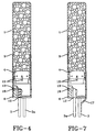
- Figure 4 is similar to Figure 3 but shows the use of a stainless steel tension spring 12 would around the earth pin 3 with its free end connected to the generator outer case 1, to provide the required short circuit link between the case 1 and earth.
- This is instead of the pressed spring 11 shown in Figure 3.
- the link between the header cap 4 and the case 1 is again provided by bent tags 10.
- An annular groove 13 of between 0.3 and 0.5mm depth is formed in the case 1 to clamp the case 1 to the fuse seal 6 and retain the two to a pull off load of up to 250 N. Stakes 18, typically eight, equispaced around the circumference of the groove serve to make the connection stronger.
- the igniter housing 8 comprises two parts: a conductive outer sleeve 13, formed for example from aluminium, and a non-conductive insert 14 which may be moulded of standard plastics material such as that known as PBT.
- the outer sleeve 13 provides a direct electrical connection to the outer case 1.
- the sleeve 13 is connected to the earth pin 3 by a stainless steel pin 15. This pin 15 is formed by a relatively small change to the anti-rotation feature.
- Figure 6 illustrates an embodiment in which the earth pin 3 is directly connected to both the outer case 1 and to the header cap 4 by using a conductive plastics material for the igniter housing 8. This will provide the low resistance short circuit path required from the header cap 4 to earth. However, in this embodiment it is necessary to insulate the other electrode pin 3a and this is done by dipping it into insulating plastics material 16 prior to moulding the housing 8 around the pins 3 and 3a.
- FIG. 7 Another embodiment is shown in Figure 7 where the outer case 1 is formed with an extending leg 17 which contacts the earth pin 3 directly.
- the header cap 4 is formed as an interference fit with tangs 10 to provide the connection from cap 4 to the case 1, as in the embodiments of Figures 2, 3 and 4.
- a circumferential groove 13 with spaced stakes is also provided to ensure a strong connection between the case 1 and the igniter housing 8 as in the embodiment of Figure 4.
Landscapes
- Engineering & Computer Science (AREA)
- Mechanical Engineering (AREA)
- Physics & Mathematics (AREA)
- Fluid Mechanics (AREA)
- General Engineering & Computer Science (AREA)
- Air Bags (AREA)
Abstract
Description
- The present invention relates to a pretensioner for a vehicle occupant safety restraint, particularly for a seat belt.
- Pretensioners are used to rapidly pull in slack in a safety restraint seat belt at the onset of a crash condition to more securely restrain the occupant against forward movement and potential injury by collision with internal features of the vehicle. In addition, the pretensioning operation aims to pull the occupant into, or at least towards, the correct seating position so as to maximise the effect of a second restraint such as an airbag.
- A modern seat belt is known as a 3-point restraint because it is secured to the vehicle at three points arranged about the occupant to provide a diagonal torso section and a horizontal lap portion to hold the occupant in the seat. The belt is attached to the vehicle by a spring loaded retractor tending to tighten in the belt, and by a buckle for quick release of the belt.
- Pretensioners are typically sited at the retractor or at the buckle end of the restraining seat belt. They are designed to store energy which when released effects the pretensioning operation. This energy may be mechanical energy in the form of a stressed spring, but more modern pretensioners are pyrotechnically operated; they comprise a sealed tube containing a gas generant which expands rapidly to release the energy to effect the pretensioning operation. The gas generant is ignited electrically via pin terminals protruding from the pretensioning tube and connected to an intermediate igniter material.
- One problem with pyrotechnically operated pretensioners is that spurious electric charges can produce inadvertent firings of the pretensioner. For example static charge may build up within the sub-assembly of the pretensioner. When the unit passes over or through any static field a low voltage will flow across the sensitive igniter material. This low voltage will in time break down the protective coating on the igniter material and once exposed it will react with oxygen and ignite thus causing the unit to fire.
- In addition, inadvertent firing will occur with single discharges of static electricity, especially across the igniter material which provides a short path between the firing pins and the igniter casing.
- The present invention aims to provide an improved pretensioner which can be used at either end of the seat belt.
- According to one aspect of the present invention there is provided a pretensioner for a vehicle occupant safety restraint comprising:
- an outer casing;
- gas generant contained within said outer case;
- an igniter comprising igniter material within an igniter housing;
- a pair of electrodes connected to said igniter material;
- a connector link comprising a resilient member electrically connecting the igniter housing to an earth path.
-
- The connector link preferably comprises a spring pressed over one of the pins. The igniter housing is again formed as an interference fit with the outer case and the spring provide the low resistance link from the case to the pin.
- The resilience of the spring maintains the electrical connections and reduces the risk of the contact being broken. This entails very little or no changes to a conventional igniter housing design.
- Preferably the connector link electrically connects the igniter housing to one of the electrodes. Advantageously the link is a very low or even almost zero resistance link and is connected to one of the pins only with a shorting connection between the two electrodes being provided.
- Thus a low resistance link is provided for the charge to take through the unit so as to prevent the build up of charge and thus inhibit spurious firing of the pretensioner.
- According to a first embodiment of the present invention the pretensioner is constructed so that the igniter housing is electrically connected to the outer case of the pretensioner, for example by making it an interference fit in the case, and one of the electrod4e pins (preferably the earthed one) forms an electrical connection to the outer case, for example it may comprise a bent section protruding through the igniter housing and fitting, interference wise, with the outer case. Thus a short circuit is provided between the igniter housing and the earthed electrode pin via the outer case to discharge spurious static currents.
- This embodiment has the advantage of requiring relatively few parts and no substantial modification of a conventional igniter housing. Also it provides for only two points which need maintain electrical connection.
- According to a second embodiment the igniter housing is made from non-conductive material and the igniter housing has a cap which is crimped with the outer case directly into a conductive sleeve, and one of the pins is modified so that a flat anti-rotation feature is extended outwards to contact with the conductive sleeve.
- This embodiment has the advantage that a relatively low number of electrical contacts are required and little modification to manufacturing tools is needed.
- According to a third embodiment the igniter housing is moulded or cast from conductive material and one of the pins is coated in an insulating material such as plastic. The igniter housing cap and the outer case are crimped directly onto a conductive sleeve thus creating a low resistance link between the conductive igniter housing and the pin. The second pin is insulated from the igniter housing.
- This has the advantage of reducing the number of electrical contacts, and requiring no additional components.
- According to a fourth embodiment the igniter housing cap is designed as an interference fit with the outer case, so as to electrically connect the two components, and an electrical connection is formed between the outer case and one of the pins, for example by an extended leg jutting from the outer case to contact the pin.
- This embodiment requires no additional parts and no modification to existing manufacturing tools.
- Of course, modifications and combinations of the features of each of the embodiments are envisaged and are intended to be within the scope of the invention.
- For a better understanding of the present invention and to show how the same may be carried into effect, reference will now be made to the accompanying drawings, in which:
- Figure 1 is a cross-sectional view of part of a known pretensioner;
- Figure 2 is a cross-sectional view of part of a pretensioner according to one embodiment of the present invention;
- Figure 3 is a cross-sectional view of part of a pretensioner according to a second embodiment of the present invention;
- Figure 4 is a cross-sectional view of part of a pretensioner according to a third embodiment of the present invention;
- Figure 5 is a cross-sectional view of part of a pretensioner according to a fourth embodiment of the present invention;
- Figure 6 is a cross-sectional view of part of a pretensioner according to a fifth embodiment of the present invention;
- Figure 7 is a cross-sectional view of part of a pretensioner according to a sixth embodiment of the present invention.
-
- In the Figures like parts are denoted by like reference numbers. The Figures show part of a pretensioner but the general construction of a pretensioner and the manner in which it is fitted into a vehicle to control a safety restraint seat belt is well known to persons skilled in the art. One such example is shown and described in EP-A-0 827 883.
- The pretensioner comprises an
outer case 1 in the form of a cylindrical tube of metallic material. This is filled with a gas generant 5 (of known composition). Within theouter case 1 is situated a small quantity ofsensitive igniter material 2 sandwiched behind anigniter header cap 4. Theigniter material 2 has a thickness indicated by 7. - Two
electrode pins seal 6 forming theigniter housing 8 at the end of theouter case 1. They are connected by means of a thin wire (not shown) welded to each pin and lying adjacent to or embedded in theigniter material 2. Thepin 3 is connected to earth and thus provides an earth path. - When electricity is applied across the
electrode pins igniter material 2. This activates the main gas generant 5. - Spurious electric charges, such as those which result from electrostatic build up, can cause an undesirable discharge of current from the
outer case 1 to theheader cap 4 and thus through thesensitive igniter material 2 to theearth pin 3. When such a current passes through theigniter material 2 it often causes ignition leading to spurious detonation of the pretensioner. - Figures 2 to 6 show several embodiments of the invention in which spurious discharges are reduced.
- A first embodiment of the invention is shown in Figure 2. The
electrode 3a has a U-bend 9 formed to connect with the inside wall of theouter case 1 and form an electrical connection therewith. In addition theheader cap 4 is modified to provide an electrical connection with the inside wall of theouter case 1 by an outwardly bent portion in the form of projectingtangs 10. Thus an electrical connection is provided between theheader cap 4 and theearth pin 3, via theouter case 1, of relatively low resistance so that spurious charges are discharged to earth before they build up sufficiently to activate thesensitive igniter material 2. - The second embodiment shown in Figure 3 utilises a pressed
metal clip 11 to provide a link from thegenerator case 1 to theearth pin 3. As in the embodiment of Figure 1 theheader cap 4 is formed as an interference fit with theouter case 1 by means oftangs 10 contacting the inside surface of theouter case 1. Again this provide a short circuit to earth for spurious charges. Thetangs 10 may be formed on assembly of the pretensioner by thecase 1 being inserted over theheader cap 4. - Figure 4 is similar to Figure 3 but shows the use of a stainless
steel tension spring 12 would around theearth pin 3 with its free end connected to the generatorouter case 1, to provide the required short circuit link between thecase 1 and earth. This is instead of the pressedspring 11 shown in Figure 3. The link between theheader cap 4 and thecase 1 is again provided bybent tags 10. Anannular groove 13 of between 0.3 and 0.5mm depth is formed in thecase 1 to clamp thecase 1 to thefuse seal 6 and retain the two to a pull off load of up to 250N. Stakes 18, typically eight, equispaced around the circumference of the groove serve to make the connection stronger. - In Figure 5 the
igniter housing 8 comprises two parts: a conductiveouter sleeve 13, formed for example from aluminium, and anon-conductive insert 14 which may be moulded of standard plastics material such as that known as PBT. Theouter sleeve 13 provides a direct electrical connection to theouter case 1. Thesleeve 13 is connected to theearth pin 3 by astainless steel pin 15. Thispin 15 is formed by a relatively small change to the anti-rotation feature. - Figure 6 illustrates an embodiment in which the
earth pin 3 is directly connected to both theouter case 1 and to theheader cap 4 by using a conductive plastics material for theigniter housing 8. This will provide the low resistance short circuit path required from theheader cap 4 to earth. However, in this embodiment it is necessary to insulate theother electrode pin 3a and this is done by dipping it into insulatingplastics material 16 prior to moulding thehousing 8 around thepins - Another embodiment is shown in Figure 7 where the
outer case 1 is formed with an extendingleg 17 which contacts theearth pin 3 directly. Theheader cap 4 is formed as an interference fit withtangs 10 to provide the connection fromcap 4 to thecase 1, as in the embodiments of Figures 2, 3 and 4. Acircumferential groove 13 with spaced stakes is also provided to ensure a strong connection between thecase 1 and theigniter housing 8 as in the embodiment of Figure 4.
Claims (10)
- A pretensioner for a vehicle occupant safety restraint comprising:an outer casing;gas generant contained within said outer case;an igniter comprising igniter material within an igniter housing;a pair of electrodes connected to said igniter material;connector link comprising a resilient member electrically connecting the igniter housing to an earth path.
- A pretensioner according to claim 1 wherein the resilient member comprises a spring pressed over one of the electrodes.
- A pretensioner according to claim 1 or 2 arranged so that the connector link electrically connects the igniter housing to one of the electrodes.
- A pretensioner according to claim 1, 2 or claim 3 wherein the link is a very low resistance link.
- A pretensioner according to any one of the preceding claims wherein the igniter housing is electrically connected to the outer case of the pretensioner.
- A pretensioner according to claim 5 wherein the igniter housing is an interference fit in the case.
- A pretensioner according to claim 5 or 6 wherein one of the electrodes forms an electrical connection to the outer case.
- A pretensioner according to claim 7, wherein said one of the electrodes comprises a bent section protruding through the igniter housing and fitting, interference wise, with the outer case.
- A pretensioner according to any one of claims 1 to 6 wherein the igniter housing is made from non-conductive material and the igniter housing has a cap which is crimped with the outer case directly into a conductive sleeve.
- A pretensioner according to claim 9 wherein one of the electrodes is modified so that a flat anti-rotation feature is extended outwards to contact with the conductive sleeve.
Applications Claiming Priority (2)
| Application Number | Priority Date | Filing Date | Title |
|---|---|---|---|
| GB9905188 | 1999-03-05 | ||
| GB9905188A GB2347485A (en) | 1999-03-05 | 1999-03-05 | Pretensioner |
Publications (3)
| Publication Number | Publication Date |
|---|---|
| EP1035400A2 true EP1035400A2 (en) | 2000-09-13 |
| EP1035400A3 EP1035400A3 (en) | 2002-06-26 |
| EP1035400B1 EP1035400B1 (en) | 2005-05-11 |
Family
ID=10849109
Family Applications (1)
| Application Number | Title | Priority Date | Filing Date |
|---|---|---|---|
| EP00301651A Expired - Lifetime EP1035400B1 (en) | 1999-03-05 | 2000-03-01 | Pretensioner with a link earthing the igniter housing |
Country Status (4)
| Country | Link |
|---|---|
| US (4) | US6234524B1 (en) |
| EP (1) | EP1035400B1 (en) |
| DE (1) | DE60019995T2 (en) |
| GB (1) | GB2347485A (en) |
Cited By (1)
| Publication number | Priority date | Publication date | Assignee | Title |
|---|---|---|---|---|
| WO2003101789A1 (en) * | 2002-05-28 | 2003-12-11 | Takata-Petri (Ulm) Gmbh | Gas generator and device for electrically contacting a gas generator |
Families Citing this family (12)
| Publication number | Priority date | Publication date | Assignee | Title |
|---|---|---|---|---|
| GB2347485A (en) * | 1999-03-05 | 2000-09-06 | Breed Automotive Tech | Pretensioner |
| DE20020098U1 (en) * | 2000-11-27 | 2001-04-05 | TRW Airbag Systems GmbH & Co. KG, 84544 Aschau | Gas generator |
| DE20020103U1 (en) * | 2000-11-27 | 2001-04-05 | TRW Airbag Systems GmbH & Co. KG, 84544 Aschau | Pyrotechnic gas generator |
| US6709011B2 (en) * | 2001-02-21 | 2004-03-23 | Autoliv Asp, Inc. | Leak detection enhancing insert for an airbag inflator assembly |
| CZ20033416A3 (en) * | 2001-05-15 | 2004-04-14 | Nippon Kayaku Kabushiki-Kaisha | Gas generator |
| US6942897B2 (en) * | 2003-02-19 | 2005-09-13 | The Board Of Trustees Of Western Michigan University | Nanoparticle barrier-coated substrate and method for making the same |
| DE102004004748A1 (en) * | 2003-03-08 | 2004-09-23 | Dynamit Nobel Ais Gmbh Automotive Ignition Systems | Glass bushing for a pyroelectric lighter |
| DE10348382A1 (en) * | 2003-10-17 | 2005-05-25 | Daimlerchrysler Ag | Pyrotechnic gas generator for road vehicle airbag deployment system has electric contacts with connections to housing to prevent accidental electric discharges igniting detonator |
| JP4335725B2 (en) * | 2004-03-30 | 2009-09-30 | 日本化薬株式会社 | Gas generator |
| US7542904B2 (en) * | 2005-08-19 | 2009-06-02 | Cisco Technology, Inc. | System and method for maintaining a speech-recognition grammar |
| EP2157399A4 (en) * | 2007-06-13 | 2013-03-20 | Nippon Kayaku Kk | Squib, gas generation device for airbag, and gas generation device for seatbelt pretensioner |
| US11760303B2 (en) * | 2021-04-19 | 2023-09-19 | Autoliv Asp, Inc. | Initiator for a gas generator of vehicle safety device |
Family Cites Families (31)
| Publication number | Priority date | Publication date | Assignee | Title |
|---|---|---|---|---|
| US3971320A (en) * | 1974-04-05 | 1976-07-27 | Ici United States Inc. | Electric initiator |
| US5400227A (en) * | 1984-09-06 | 1995-03-21 | Mag Instrument, Inc. | Tailcap switch focus flashlight |
| US4745858A (en) * | 1986-09-26 | 1988-05-24 | Ireco Incorporated | Electric detonator with static electricity suppression |
| GB8926073D0 (en) * | 1989-11-17 | 1990-01-10 | Amp Gmbh | Shunting device for use in electrical connectors |
| US5140906A (en) * | 1991-11-05 | 1992-08-25 | Ici Americas, Inc. | Airbag igniter having double glass seal |
| US5454320A (en) * | 1992-10-23 | 1995-10-03 | Quantic Industries, Inc. | Air bag initiator |
| DE4307774A1 (en) * | 1993-03-12 | 1994-09-15 | Dynamit Nobel Ag | Ignition device |
| JP2700100B2 (en) * | 1993-05-28 | 1998-01-19 | 日本工機株式会社 | Igniter |
| US5596163A (en) * | 1993-08-25 | 1997-01-21 | Ems-Patvag Ag | Gas generator igniting capsule |
| US5728964A (en) * | 1993-10-20 | 1998-03-17 | Quantic Industries, Inc. | Electrical initiator |
| ZA948566B (en) * | 1993-11-18 | 1995-05-18 | Ici America Inc | Airbag igniter and method of manufacture |
| US5487559A (en) * | 1994-09-13 | 1996-01-30 | Trw Inc. | Air bag inflator with pressure sensor |
| DE4435319A1 (en) * | 1994-10-01 | 1996-04-04 | Temic Bayern Chem Airbag Gmbh | Ignition unit for a gas generator of a passive restraint system |
| DE4441901C2 (en) * | 1994-11-24 | 1998-07-02 | Siemens Ag | MOSFET on SOI substrate and method for its production |
| US5621183A (en) * | 1995-01-12 | 1997-04-15 | Trw Inc. | Initiator for an air bag inflator |
| US5556132A (en) * | 1995-04-13 | 1996-09-17 | Trw Inc. | Vehicle occupant restraint with auto ignition material |
| US5623115A (en) | 1995-05-30 | 1997-04-22 | Morton International, Inc. | Inflator for a vehicle airbag system and a pyrogen igniter used therein |
| US5558366A (en) * | 1995-08-22 | 1996-09-24 | Trw Inc. | Initiator assembly for air bag inflator |
| US5662353A (en) * | 1995-12-06 | 1997-09-02 | Trw Vehicle Safety Systems Inc. | Electrical conductor for air bag inflator |
| US5672841A (en) * | 1995-12-15 | 1997-09-30 | Morton International, Inc. | Inflator initiator with zener diode electrostatic discharge protection |
| US5932832A (en) * | 1996-04-15 | 1999-08-03 | Autoliv Asp, Inc. | High pressure resistant initiator with integral metal oxide varistor for electro-static discharge protection |
| GB2315985B (en) | 1996-08-13 | 2000-11-22 | Alliedsignal Ltd | Pretensioner |
| US5882224A (en) * | 1996-08-28 | 1999-03-16 | Thomas & Betts International, Inc. | Squib connector socker assembly having shorting clip for automotive air bags |
| US5821446A (en) * | 1997-05-27 | 1998-10-13 | Trw Inc. | Inflator for an inflatable vehicle occupant protection device |
| US5920029A (en) * | 1997-05-30 | 1999-07-06 | Emerson Electric Company | Igniter assembly and method |
| US5944545A (en) * | 1997-08-29 | 1999-08-31 | Talley Defense Systems, Inc. | Single pin coaxial initiator, retainer and connector and method of operation |
| US6009809A (en) * | 1997-12-12 | 2000-01-04 | Automotive Systems Laboratory, Inc. | Bridgewire initiator |
| US6007096A (en) * | 1998-04-20 | 1999-12-28 | Trw Inc. | Inflator having a pressure monitoring initiator |
| US6082758A (en) * | 1998-08-17 | 2000-07-04 | General Motors Corporation | Driver air bag horn ground spring |
| GB2347485A (en) * | 1999-03-05 | 2000-09-06 | Breed Automotive Tech | Pretensioner |
| US6167808B1 (en) * | 1999-04-06 | 2001-01-02 | Trw Inc. | Initiator for air bag inflator |
-
1999
- 1999-03-05 GB GB9905188A patent/GB2347485A/en not_active Withdrawn
- 1999-07-02 US US09/347,500 patent/US6234524B1/en not_active Expired - Fee Related
-
2000
- 2000-03-01 EP EP00301651A patent/EP1035400B1/en not_active Expired - Lifetime
- 2000-03-01 DE DE60019995T patent/DE60019995T2/en not_active Expired - Fee Related
-
2001
- 2001-03-02 US US09/796,947 patent/US6283506B2/en not_active Expired - Fee Related
- 2001-03-02 US US09/796,948 patent/US6412817B2/en not_active Expired - Fee Related
- 2001-03-02 US US09/797,550 patent/US6286865B2/en not_active Expired - Fee Related
Non-Patent Citations (1)
| Title |
|---|
| None |
Cited By (2)
| Publication number | Priority date | Publication date | Assignee | Title |
|---|---|---|---|---|
| WO2003101789A1 (en) * | 2002-05-28 | 2003-12-11 | Takata-Petri (Ulm) Gmbh | Gas generator and device for electrically contacting a gas generator |
| US7686325B2 (en) | 2002-05-28 | 2010-03-30 | Takata-Petri Ag | Gas generator and device for electrically contacting a gas generator |
Also Published As
| Publication number | Publication date |
|---|---|
| US20010006290A1 (en) | 2001-07-05 |
| DE60019995T2 (en) | 2006-05-04 |
| US6283506B2 (en) | 2001-09-04 |
| EP1035400B1 (en) | 2005-05-11 |
| EP1035400A3 (en) | 2002-06-26 |
| US6234524B1 (en) | 2001-05-22 |
| US20010008338A1 (en) | 2001-07-19 |
| GB2347485A (en) | 2000-09-06 |
| GB9905188D0 (en) | 1999-04-28 |
| US6412817B2 (en) | 2002-07-02 |
| US6286865B2 (en) | 2001-09-11 |
| DE60019995D1 (en) | 2005-06-16 |
| US20010009330A1 (en) | 2001-07-26 |
Similar Documents
| Publication | Publication Date | Title |
|---|---|---|
| EP0779492B1 (en) | Inflator initiator with zener diode electrostatic discharge protector | |
| US5433147A (en) | Ignition device | |
| US6009809A (en) | Bridgewire initiator | |
| US6234524B1 (en) | Pretensioner | |
| JP2700100B2 (en) | Igniter | |
| US4369707A (en) | Short circuit fuse for electrical igniters | |
| US6220163B1 (en) | Electro-pyrotechnic initiation system protected against electrostatic discharges | |
| US5621197A (en) | Device for interrupting the flow of current in the positive or impregnated vehicle battery cable | |
| EP1227016A1 (en) | Gas generator | |
| US5616881A (en) | Inflator socket pin collar for integrated circuit initaitor with integral metal oxide varistor for electro-static discharge protections | |
| US6146598A (en) | Initiator unit having a self locking two wire connector for pyrotecnic generators | |
| US20040112244A1 (en) | Initiator assembly with integrated shorting element | |
| US8056477B2 (en) | Protection system for use with airbag inflators and initiators | |
| US6732655B1 (en) | Ignition device for restraint means in a vehicle | |
| WO2004059239A1 (en) | Gas producer | |
| US20030150348A1 (en) | Initiator and gas generator | |
| JP3034225B2 (en) | Belt pretensioning device | |
| US20060208474A1 (en) | Gas producer | |
| WO1998002711A1 (en) | Electro-explosive device | |
| JP2023133020A (en) | Ignition device | |
| JP2536357Y2 (en) | Ignition structure of igniter in gas generator for airbag deployment | |
| WO2000073729A1 (en) | Igniter, header assembly, and igniter plug | |
| WO2008023022A1 (en) | A part for connecting a gas micro-generator to initiation means | |
| HK1042742B (en) | Ignition unit for a passenger protection device of a motor vehicle |
Legal Events
| Date | Code | Title | Description |
|---|---|---|---|
| PUAI | Public reference made under article 153(3) epc to a published international application that has entered the european phase |
Free format text: ORIGINAL CODE: 0009012 |
|
| AK | Designated contracting states |
Kind code of ref document: A2 Designated state(s): AT BE CH CY DE DK ES FI FR GB GR IE IT LI LU MC NL PT SE |
|
| AX | Request for extension of the european patent |
Free format text: AL;LT;LV;MK;RO;SI |
|
| PUAL | Search report despatched |
Free format text: ORIGINAL CODE: 0009013 |
|
| AK | Designated contracting states |
Kind code of ref document: A3 Designated state(s): AT BE CH CY DE DK ES FI FR GB GR IE IT LI LU MC NL PT SE |
|
| AX | Request for extension of the european patent |
Free format text: AL;LT;LV;MK;RO;SI |
|
| 17P | Request for examination filed |
Effective date: 20020718 |
|
| 17Q | First examination report despatched |
Effective date: 20020918 |
|
| AKX | Designation fees paid |
Designated state(s): DE FR GB IT |
|
| RAP1 | Party data changed (applicant data changed or rights of an application transferred) |
Owner name: BREED AUTOMOTIVE TECHNOLOGY, INC. |
|
| GRAP | Despatch of communication of intention to grant a patent |
Free format text: ORIGINAL CODE: EPIDOSNIGR1 |
|
| RAP1 | Party data changed (applicant data changed or rights of an application transferred) |
Owner name: KEY SAFETY SYSTEMS, INC. |
|
| GRAS | Grant fee paid |
Free format text: ORIGINAL CODE: EPIDOSNIGR3 |
|
| GRAA | (expected) grant |
Free format text: ORIGINAL CODE: 0009210 |
|
| AK | Designated contracting states |
Kind code of ref document: B1 Designated state(s): DE FR GB IT |
|
| REG | Reference to a national code |
Ref country code: GB Ref legal event code: FG4D |
|
| REG | Reference to a national code |
Ref country code: IE Ref legal event code: FG4D |
|
| REF | Corresponds to: |
Ref document number: 60019995 Country of ref document: DE Date of ref document: 20050616 Kind code of ref document: P |
|
| PLBE | No opposition filed within time limit |
Free format text: ORIGINAL CODE: 0009261 |
|
| STAA | Information on the status of an ep patent application or granted ep patent |
Free format text: STATUS: NO OPPOSITION FILED WITHIN TIME LIMIT |
|
| ET | Fr: translation filed | ||
| 26N | No opposition filed |
Effective date: 20060214 |
|
| PGFP | Annual fee paid to national office [announced via postgrant information from national office to epo] |
Ref country code: GB Payment date: 20070202 Year of fee payment: 8 |
|
| PGFP | Annual fee paid to national office [announced via postgrant information from national office to epo] |
Ref country code: DE Payment date: 20070330 Year of fee payment: 8 |
|
| PGFP | Annual fee paid to national office [announced via postgrant information from national office to epo] |
Ref country code: IT Payment date: 20070611 Year of fee payment: 8 |
|
| PGFP | Annual fee paid to national office [announced via postgrant information from national office to epo] |
Ref country code: FR Payment date: 20070301 Year of fee payment: 8 |
|
| GBPC | Gb: european patent ceased through non-payment of renewal fee |
Effective date: 20080301 |
|
| REG | Reference to a national code |
Ref country code: FR Ref legal event code: ST Effective date: 20081125 |
|
| PG25 | Lapsed in a contracting state [announced via postgrant information from national office to epo] |
Ref country code: DE Free format text: LAPSE BECAUSE OF NON-PAYMENT OF DUE FEES Effective date: 20081001 |
|
| PG25 | Lapsed in a contracting state [announced via postgrant information from national office to epo] |
Ref country code: FR Free format text: LAPSE BECAUSE OF NON-PAYMENT OF DUE FEES Effective date: 20080331 |
|
| PG25 | Lapsed in a contracting state [announced via postgrant information from national office to epo] |
Ref country code: GB Free format text: LAPSE BECAUSE OF NON-PAYMENT OF DUE FEES Effective date: 20080301 |
|
| PG25 | Lapsed in a contracting state [announced via postgrant information from national office to epo] |
Ref country code: IT Free format text: LAPSE BECAUSE OF NON-PAYMENT OF DUE FEES Effective date: 20080301 |