EP1035343A1 - Compliant cage for a roller-type bi-directional one-way clutch mechanism - Google Patents
Compliant cage for a roller-type bi-directional one-way clutch mechanism Download PDFInfo
- Publication number
- EP1035343A1 EP1035343A1 EP00301360A EP00301360A EP1035343A1 EP 1035343 A1 EP1035343 A1 EP 1035343A1 EP 00301360 A EP00301360 A EP 00301360A EP 00301360 A EP00301360 A EP 00301360A EP 1035343 A1 EP1035343 A1 EP 1035343A1
- Authority
- EP
- European Patent Office
- Prior art keywords
- members
- roller
- cage
- clutch mechanism
- recesses
- Prior art date
- Legal status (The legal status is an assumption and is not a legal conclusion. Google has not performed a legal analysis and makes no representation as to the accuracy of the status listed.)
- Withdrawn
Links
Images

Classifications
-
- F—MECHANICAL ENGINEERING; LIGHTING; HEATING; WEAPONS; BLASTING
- F16—ENGINEERING ELEMENTS AND UNITS; GENERAL MEASURES FOR PRODUCING AND MAINTAINING EFFECTIVE FUNCTIONING OF MACHINES OR INSTALLATIONS; THERMAL INSULATION IN GENERAL
- F16C—SHAFTS; FLEXIBLE SHAFTS; ELEMENTS OR CRANKSHAFT MECHANISMS; ROTARY BODIES OTHER THAN GEARING ELEMENTS; BEARINGS
- F16C33/00—Parts of bearings; Special methods for making bearings or parts thereof
- F16C33/30—Parts of ball or roller bearings
- F16C33/46—Cages for rollers or needles
-
- F—MECHANICAL ENGINEERING; LIGHTING; HEATING; WEAPONS; BLASTING
- F16—ENGINEERING ELEMENTS AND UNITS; GENERAL MEASURES FOR PRODUCING AND MAINTAINING EFFECTIVE FUNCTIONING OF MACHINES OR INSTALLATIONS; THERMAL INSULATION IN GENERAL
- F16D—COUPLINGS FOR TRANSMITTING ROTATION; CLUTCHES; BRAKES
- F16D41/00—Freewheels or freewheel clutches
- F16D41/06—Freewheels or freewheel clutches with intermediate wedging coupling members between an inner and an outer surface
- F16D41/064—Freewheels or freewheel clutches with intermediate wedging coupling members between an inner and an outer surface the intermediate members wedging by rolling and having a circular cross-section, e.g. balls
- F16D41/066—Freewheels or freewheel clutches with intermediate wedging coupling members between an inner and an outer surface the intermediate members wedging by rolling and having a circular cross-section, e.g. balls all members having the same size and only one of the two surfaces being cylindrical
- F16D41/067—Freewheels or freewheel clutches with intermediate wedging coupling members between an inner and an outer surface the intermediate members wedging by rolling and having a circular cross-section, e.g. balls all members having the same size and only one of the two surfaces being cylindrical and the members being distributed by a separate cage encircling the axis of rotation
-
- F—MECHANICAL ENGINEERING; LIGHTING; HEATING; WEAPONS; BLASTING
- F16—ENGINEERING ELEMENTS AND UNITS; GENERAL MEASURES FOR PRODUCING AND MAINTAINING EFFECTIVE FUNCTIONING OF MACHINES OR INSTALLATIONS; THERMAL INSULATION IN GENERAL
- F16D—COUPLINGS FOR TRANSMITTING ROTATION; CLUTCHES; BRAKES
- F16D41/00—Freewheels or freewheel clutches
- F16D41/06—Freewheels or freewheel clutches with intermediate wedging coupling members between an inner and an outer surface
- F16D41/08—Freewheels or freewheel clutches with intermediate wedging coupling members between an inner and an outer surface with provision for altering the freewheeling action
- F16D41/086—Freewheels or freewheel clutches with intermediate wedging coupling members between an inner and an outer surface with provision for altering the freewheeling action the intermediate members being of circular cross-section and wedging by rolling
- F16D41/088—Freewheels or freewheel clutches with intermediate wedging coupling members between an inner and an outer surface with provision for altering the freewheeling action the intermediate members being of circular cross-section and wedging by rolling the intermediate members being of only one size and wedging by a movement not having an axial component, between inner and outer races, one of which is cylindrical
-
- F—MECHANICAL ENGINEERING; LIGHTING; HEATING; WEAPONS; BLASTING
- F16—ENGINEERING ELEMENTS AND UNITS; GENERAL MEASURES FOR PRODUCING AND MAINTAINING EFFECTIVE FUNCTIONING OF MACHINES OR INSTALLATIONS; THERMAL INSULATION IN GENERAL
- F16D—COUPLINGS FOR TRANSMITTING ROTATION; CLUTCHES; BRAKES
- F16D41/00—Freewheels or freewheel clutches
- F16D41/06—Freewheels or freewheel clutches with intermediate wedging coupling members between an inner and an outer surface
- F16D41/08—Freewheels or freewheel clutches with intermediate wedging coupling members between an inner and an outer surface with provision for altering the freewheeling action
- F16D41/10—Freewheels or freewheel clutches with intermediate wedging coupling members between an inner and an outer surface with provision for altering the freewheeling action with self-actuated reversing
-
- F—MECHANICAL ENGINEERING; LIGHTING; HEATING; WEAPONS; BLASTING
- F16—ENGINEERING ELEMENTS AND UNITS; GENERAL MEASURES FOR PRODUCING AND MAINTAINING EFFECTIVE FUNCTIONING OF MACHINES OR INSTALLATIONS; THERMAL INSULATION IN GENERAL
- F16C—SHAFTS; FLEXIBLE SHAFTS; ELEMENTS OR CRANKSHAFT MECHANISMS; ROTARY BODIES OTHER THAN GEARING ELEMENTS; BEARINGS
- F16C2361/00—Apparatus or articles in engineering in general
- F16C2361/43—Clutches, e.g. disengaging bearing
Definitions
- This invention relates to one-way roller-type clutch mechanisms and improved compliant cage devices therefor.
- roller clutch mechanisms there are many types of one-way roller clutch mechanisms - whether one directional or bi-directional -in use today. These roller clutch mechanisms have particular use in vehicle transfer case applications, although they also have use in many other applications, such as vehicle rear differentials, vehicle and machine transmissions, and other mechanical industrial applications utilizing rotating machinery. In transfer cases, the system provides transfer of torque from the driving wheels to the non-driving wheels whenever the driving wheels experience slippage.
- the outer surface of the inner race member typically has a wavy cam-type surface, with a roller member being positioned between each of the cams.
- the rollers form a rocking wedge between the driven and drive shafts to drive the driven shaft in a selected direction.
- Many of these mechanisms are two-way devices and are generally relatively complicated in that some form of spring or shifting mechanism is required to change from a drive in one direction to a drive in the opposite direction.
- a known one-way roller-type clutch mechanism is shown, for example, in co-owned U.S. Patent No. 4,848,508.
- Other known clutch mechanisms are disclosed in U.S. Patent Nos. 5,195,604, 5,307,911, 5,443,147, and 5,542,515.
- the problems and disadvantages with known cage-type one-way roller clutch mechanisms are overcome with the present invention.
- the present invention provides a roller-type one-way clutch mechanism with an improved cage device, particularly for bi-directional use.
- the cage device preferably incorporates spring-like segments which provide resiliency for the clutch mechanism. When the clutch mechanism engages and loads are applied to it, differences in geometries from cam-to-cam and roller-to-roller will result in circumferential loading on the cage device.
- the resilient spring members reduce the magnitude of these loads and prevent fatigue fracture of the cage device and other premature failure.
- the annular cage device has a plurality of pockets based around its circumference in which the roller members are positioned.
- the pocket members have curved side surfaces conforming to the shape of the roller members, as well as one or more recesses adjacent the side surfaces of the pocket members. In alternate embodiments, one, two or more recesses are provided adjacent at least one side surface of each pocket member. Also, for increased resiliency, spring-like members can be provided adjacent each side of each of the pocket members.
- the resilient cage is combined with a plurality of separate resilient spring members.
- the spring members are provided around the circumference of the cage member and positioned in contact with the roller members.
- the spring members provide the requisite resiliency for the clutch mechanism.
- the configuration and structure of the cage member facilitates ease of manufacture since it is designed to be made by an injection molding process with an axial pull operation.
- the clutch mechanism 10 is generally referred to by the reference numeral 10.
- the clutch mechanism 10 includes an outer race member 12, an inner race member 14, a plurality of roller members 16 positioned in between the inner and outer race members, and a cage device or member 18.
- the outer surface of the inner race member 14 has a cam-type surface 15.
- the present invention has a number of uses and applications and can be used, for example, in vehicle transfer case applications, vehicle rear differentials, vehicle and machine transmissions, and other industrial applications utilizing rotating machinery.
- vehicle transfer case applications for example, vehicle transfer case applications, vehicle rear differentials, vehicle and machine transmissions, and other industrial applications utilizing rotating machinery.
- One such use is shown, for example, in co-owned U.S. Patent No. 4,848,508, the disclosure of which is hereby incorporated by reference herein.
- the outer surface 20 of the outer race member 12 can be provided with various interlocking, toothed or splined structures in order to mate with and drive part of the mechanical mechanism or structure in which the clutch mechanism is situated.
- a plurality of spline or teeth members 22 are shown in Figure 1.
- the inner surface 24 of the inner race member 14 can have a plurality of teeth members 26 or similar spline-type structures in order to be secured to a shaft or other member positioned inside the inner race member.
- the roller members 16 can be of any conventional type, but preferably have a round cylindrical shape.
- the roller members are made from a metal material, such as high strength or hardened steel, and can be cut from a drawn wire of such material.
- the cage device or member 18 which preferably is used with the present invention is shown in Figures 1-5.
- the cage member 18 has an annular or ring shape and is preferably made from a plastic material, such as nylon or a fiberglass reinforced engineering polymer. It is also possible, but not preferred, to make the cage member from a metal or similar material.
- a plurality of cross-members 34 are provided around the circumference of the cage member 18 forming windows 30.
- the windows are positioned around the circumference of the cage member and each are adapted to have a roller member 16 positioned therein.
- the windows are evenly spaced in order to maximize the load capacity of the clutch assembly.
- each of the cross-members or windows 30 are curved to conform to the shape of the roller members 16.
- a roller member 16' is shown in phantom lines in Figure 5 positioned in one of the windows 30.
- a pair of resilient spring-like members (or leaf segments) 36 are attached to each of the cross-members 34 and are adapted to come in contact with the outer surfaces of the roller members.
- Recesses or grooves 38 are provided between each of the resilient spring-like members 36 and the body of each of the cross-members 34. Grooves 38 provide clearance for the spring-like members 36 to be deformed when the roller members are placed under load.
- the spring-like members 36 are not connected at their outer edges 40 (as shown in Figures 2 and 3) This allows the members 36 to deflect more easily without developing excessive loads.
- the spring members also accommodate any tolerance differences between the various members of the clutch mechanism. In this regard, slight differences in dimensions between roller diameters, cam-to-cam distances, roller travel distances on the cam surfaces, etc., can lead to unacceptable forces being applied to the cage device. These forces over time can lead to fatigue fracture of the cage devices and premature failure of the clutch mechanism.
- the spring-like leaf members or segments 36 build resilience into the one-way clutch mechanism 10. When the clutch is engaged and loads are applied to the race members, any differences between the geometries from cam-to-cam on the outer surface 15 of the inner race member 14 and from roller-to-roller 16, will result in non-uniform circumferential loading on the cage member 18.
- the compliant leaf-segments 36 reduce the magnitude of those loads and prevent fatigue fracture of the cage material and other types of premature failure.
- the compliant cage member 50 has smaller cross member body portions 52 and pairs of recesses 54 and 56 positioned between each window 58 where the roller members 16' are positioned.
- Each of the windows have curved side surfaces 60 thereon and a pair of spring-like members 62 and 64 formed by the recesses.
- the pair of spring-like leaf members 62 and 64 provide additional resiliency and ability to reduce the magnitude of loads applied to the clutch mechanism.
- Figure 7 shows still another cage device or member 70 with cross members 72, a plurality of windows 74, and a plurality of spring-like leaf members 76 positioned adjacent each window.
- the spring members 76 have recesses 78 formed between them and the body portions of the cross members 72.
- the spring members 76 also have shallow concave lower surfaces 80 which allow the spring-like member 76 to bend more easily and thus more easily absorb more of the loads in the clutch mechanism 10 during engagement.
- a further compliant cage member 90 is shown in Figure 8.
- the cage member 90 has a plurality of windows 92, a plurality of cross members 94 positioned between each of the windows, and a plurality of spring-like members 96 with curved surfaces 98 positioned on either side of the roller members (shown in phantom by reference numeral 16').
- Recesses 100 are provided adjacent each of the spring-members 96, and second smaller recesses 102 are provided which help provide added resiliency to the cage device.
- the recesses 102 are provided in the spring members 96 and allow the spring members to be more flexible.
- Figures 9 and 10 show still additional embodiments of the invention.
- the compliant cage member 110 has a plurality of windows 112, cross-members 114 and spring members 116.
- One spring member is positioned between each of the rollers 16' and only on one side thereof.
- the spring members 116 have curved surfaces 118 which mate with one side of the rollers 16', while the cross-members 114 have the other curved surface 120.
- a pair of recesses 122,124 are provided in each of the spring members 116, with one of the recesses 122 opening radially outwardly, while the other recess 124 opens radially inwardly.
- the compliant cage member 130 has a plurality of windows 132, a plurality of cross-members 134, and a plurality of spring-like members 136.
- One of the spring-like members 136 is positioned on either side of each of the rollers 16', and the spring-like members each have a curved surface 138 for mating with the curvature of a roller and nesting it between two adjacent spring-like members.
- each of the spring-like members have a pair of recesses 140. In this embodiment, the recesses are positioned to open radially inwardly in the cage member.
- FIGs 11-15 illustrate another embodiment of the invention in which the cage member is made in one piece by a straight pull or axial pull injection molding process and separate resilient spring members are utilized.
- the axial pull direction is shown by the arrow 148).
- the cage member is shown in Figure 13 and designated by the reference numeral 150.
- the separate spring members 180 are shown in Figures 11 and 12.
- the cage member 150 has a plurality of openings 152 evenly spaced around its periphery. Roller members 160 are positioned in each of the openings when the clutch mechanism is assembled. Radially staggered support members 154 and 156 are provided on the two sides or ends of each of the openings 152 in order to hold the roller members 160 axially in place. Axially staggered support members 162 and 164 are positioned between each of the roller openings. Adjacent each of the axially staggered support members 162 and 164 are slots or openings 166 which are used for placement of the separate spring members 180 (shown in Figures 11 and 12).
- the spring members 180 which preferably are made of spring steel or a similar material, are positioned on the cage member 150 with center portions 182 situated in openings 166 and with the two end portions 184 positioned in adjacent roller openings 152.
- the spring members have leaf-spring elements 186 at either end which are used to bias the roller members 160.
- a plurality of tabs or barbs 190 can be provided on the spring members, such as shown in Figure 12A. The barbs 190 will dig into the material forming the cage member and keep the spring members securely positioned on the cage member.
- the slots 160 could alternatively be provided on the same axial side of the cage member.
- the spring members 180 could be assembled on the cage member by axially sliding the spring members onto the cage member.
Landscapes
- Engineering & Computer Science (AREA)
- General Engineering & Computer Science (AREA)
- Mechanical Engineering (AREA)
- Rolling Contact Bearings (AREA)
- Mechanical Operated Clutches (AREA)
Abstract
A bi-directional one-way clutch mechanism (10) with
a compliant cage member (18). The clutch mechanism has a
plurality of roller members (16) positioned between inner (14) and
outer (12) race members. A compliant cage member is also
positioned between the race members and acts to hold the
roller members in place and also to reduce the magnitude
of loads applied to the roller members when the clutch
mechanism is engaged. The roller members are positioned
in windows (30) in the cage members and integral spring-like
leaf segments (36,76,96,186) are positioned in each of the windows on
either side of the roller members. One or two spring-like
members, together with one or more recesses between
each of the windows and roller members provide
resiliency for the cage mechanism. The compliant cage
device reduces the magnitude of the loads applied to the
clutch mechanism and prevent fatigue fracture and
premature failure of the cage device. In an alternate
embodiment, a one-piece injection molded compliant cage
mechanism is utilized with separate metal spring members (186)
for biasing the roller members.
Description
- This invention relates to one-way roller-type clutch mechanisms and improved compliant cage devices therefor.
- There are many types of one-way roller clutch mechanisms - whether one directional or bi-directional -in use today. These roller clutch mechanisms have particular use in vehicle transfer case applications, although they also have use in many other applications, such as vehicle rear differentials, vehicle and machine transmissions, and other mechanical industrial applications utilizing rotating machinery. In transfer cases, the system provides transfer of torque from the driving wheels to the non-driving wheels whenever the driving wheels experience slippage.
- In bi-directional roller clutch mechanisms, the outer surface of the inner race member typically has a wavy cam-type surface, with a roller member being positioned between each of the cams. In these clutch mechanisms, the rollers form a rocking wedge between the driven and drive shafts to drive the driven shaft in a selected direction. Many of these mechanisms are two-way devices and are generally relatively complicated in that some form of spring or shifting mechanism is required to change from a drive in one direction to a drive in the opposite direction.
- Also, when the clutch mechanism engages, end loads are applied and the magnitude of the loads can be substantial. Even within normal tolerance ranges, slight differences between roller diameters, cam surfaces and roller travel distances can lead to fatigue of the cage mechanisms and/or premature failure of the cage or clutch mechanism.
- A known one-way roller-type clutch mechanism is shown, for example, in co-owned U.S. Patent No. 4,848,508. Other known clutch mechanisms are disclosed in U.S. Patent Nos. 5,195,604, 5,307,911, 5,443,147, and 5,542,515.
- It is an object of the present invention to provide an improved one-way cage mechanism for a clutch mechanism. It is another object of the present invention to provide an improved cage mechanism for a bi-directional one-way clutch mechanism.
- It is a further object of the present invention to provide a cage mechanism for a clutch assembly which reduces magnitudes of loads in the clutch mechanism and minimizes fatigue and/or premature failure of the cage mechanism. It is a still further object of the present invention to provide a compliant cage mechanism for a clutch assembly which is more economical to manufacture.
- The problems and disadvantages with known cage-type one-way roller clutch mechanisms are overcome with the present invention. The present invention provides a roller-type one-way clutch mechanism with an improved cage device, particularly for bi-directional use. The cage device preferably incorporates spring-like segments which provide resiliency for the clutch mechanism. When the clutch mechanism engages and loads are applied to it, differences in geometries from cam-to-cam and roller-to-roller will result in circumferential loading on the cage device. The resilient spring members reduce the magnitude of these loads and prevent fatigue fracture of the cage device and other premature failure.
- The annular cage device has a plurality of pockets based around its circumference in which the roller members are positioned. The pocket members have curved side surfaces conforming to the shape of the roller members, as well as one or more recesses adjacent the side surfaces of the pocket members. In alternate embodiments, one, two or more recesses are provided adjacent at least one side surface of each pocket member. Also, for increased resiliency, spring-like members can be provided adjacent each side of each of the pocket members.
- In another embodiment of the invention, the resilient cage is combined with a plurality of separate resilient spring members. The spring members are provided around the circumference of the cage member and positioned in contact with the roller members. The spring members provide the requisite resiliency for the clutch mechanism. The configuration and structure of the cage member facilitates ease of manufacture since it is designed to be made by an injection molding process with an axial pull operation.
- These and other features, benefits, and advantages of the present invention will become apparent from the following description of the invention when viewed in accordance with the attached drawings and appended claims.
-
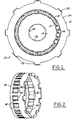
- FIGURE 1 illustrates a one-way clutch mechanism in accordance with the present invention;
- FIGURE 2 is a perspective of a compliant cage device in accordance with the present invention;
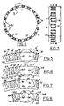
- FIGURE 3 is a side view of the cage device shown in Figure 2;
- FIGURE 4 is a cross-sectional view of the cage device shown in Figures 2 and 3, the cross-section being taken along line 4-4 in Figure 3 and in the direction of the arrows;
- FIGURE 5 is an enlarged view of a portion of the cage device shown in Figure 4;
- FIGURES 6-10 illustrate alternate embodiments of cage devices in accordance with the present invention; and
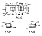
- FIGURES 11-15 illustrate another embodiment of the invention (and components thereof) in which a resilient spring member is utilized in combination with a compliant cage member injection molded by an axial pull procedure.
-
- As shown in Figure 1, the clutch mechanism is generally referred to by the reference numeral 10. The clutch mechanism 10 includes an
outer race member 12, aninner race member 14, a plurality ofroller members 16 positioned in between the inner and outer race members, and a cage device ormember 18. The outer surface of theinner race member 14 has a cam-type surface 15. - The present invention has a number of uses and applications and can be used, for example, in vehicle transfer case applications, vehicle rear differentials, vehicle and machine transmissions, and other industrial applications utilizing rotating machinery. One such use is shown, for example, in co-owned U.S. Patent No. 4,848,508, the disclosure of which is hereby incorporated by reference herein.
- In accordance with known clutch mechanisms, the
outer surface 20 of theouter race member 12 can be provided with various interlocking, toothed or splined structures in order to mate with and drive part of the mechanical mechanism or structure in which the clutch mechanism is situated. In this regard, a plurality of spline orteeth members 22 are shown in Figure 1. - Similarly, the
inner surface 24 of theinner race member 14 can have a plurality ofteeth members 26 or similar spline-type structures in order to be secured to a shaft or other member positioned inside the inner race member. - The
roller members 16 can be of any conventional type, but preferably have a round cylindrical shape. The roller members are made from a metal material, such as high strength or hardened steel, and can be cut from a drawn wire of such material. - The cage device or
member 18 which preferably is used with the present invention is shown in Figures 1-5. Thecage member 18 has an annular or ring shape and is preferably made from a plastic material, such as nylon or a fiberglass reinforced engineering polymer. It is also possible, but not preferred, to make the cage member from a metal or similar material. - A plurality of
cross-members 34 are provided around the circumference of thecage member 18 formingwindows 30. The windows are positioned around the circumference of the cage member and each are adapted to have aroller member 16 positioned therein. Preferably, the windows are evenly spaced in order to maximize the load capacity of the clutch assembly. - The
side surfaces 32 of each of the cross-members orwindows 30 are curved to conform to the shape of theroller members 16. In this regard, a roller member 16' is shown in phantom lines in Figure 5 positioned in one of thewindows 30. - A pair of resilient spring-like members (or leaf segments) 36 are attached to each of the
cross-members 34 and are adapted to come in contact with the outer surfaces of the roller members. Recesses orgrooves 38 are provided between each of the resilient spring-like members 36 and the body of each of thecross-members 34.Grooves 38 provide clearance for the spring-like members 36 to be deformed when the roller members are placed under load. - The spring-
like members 36 are not connected at their outer edges 40 (as shown in Figures 2 and 3) This allows themembers 36 to deflect more easily without developing excessive loads. The spring members also accommodate any tolerance differences between the various members of the clutch mechanism. In this regard, slight differences in dimensions between roller diameters, cam-to-cam distances, roller travel distances on the cam surfaces, etc., can lead to unacceptable forces being applied to the cage device. These forces over time can lead to fatigue fracture of the cage devices and premature failure of the clutch mechanism. - The spring-like leaf members or
segments 36 build resilience into the one-way clutch mechanism 10. When the clutch is engaged and loads are applied to the race members, any differences between the geometries from cam-to-cam on theouter surface 15 of theinner race member 14 and from roller-to-roller 16, will result in non-uniform circumferential loading on thecage member 18. The compliant leaf-segments 36 reduce the magnitude of those loads and prevent fatigue fracture of the cage material and other types of premature failure. - Other embodiments of compliant cage devices or members in accordance with the present invention are shown in Figures 6-10. In Figure 6, the
compliant cage member 50 has smaller crossmember body portions 52 and pairs ofrecesses like members like leaf members - Figure 7 shows still another cage device or member 70 with
cross members 72, a plurality ofwindows 74, and a plurality of spring-like leaf members 76 positioned adjacent each window. Thespring members 76 haverecesses 78 formed between them and the body portions of thecross members 72. Thespring members 76 also have shallow concavelower surfaces 80 which allow the spring-like member 76 to bend more easily and thus more easily absorb more of the loads in the clutch mechanism 10 during engagement. - A further
compliant cage member 90 is shown in Figure 8. Thecage member 90 has a plurality ofwindows 92, a plurality ofcross members 94 positioned between each of the windows, and a plurality of spring-like members 96 withcurved surfaces 98 positioned on either side of the roller members (shown in phantom by reference numeral 16').Recesses 100 are provided adjacent each of the spring-members 96, and secondsmaller recesses 102 are provided which help provide added resiliency to the cage device. Therecesses 102 are provided in thespring members 96 and allow the spring members to be more flexible. - Figures 9 and 10 show still additional embodiments of the invention. In Figure 9, the
compliant cage member 110 has a plurality ofwindows 112,cross-members 114 andspring members 116. One spring member is positioned between each of the rollers 16' and only on one side thereof. Thespring members 116 have curved surfaces 118 which mate with one side of the rollers 16', while the cross-members 114 have the othercurved surface 120. A pair of recesses 122,124 are provided in each of thespring members 116, with one of therecesses 122 opening radially outwardly, while theother recess 124 opens radially inwardly. - In Figure 10, the
compliant cage member 130 has a plurality ofwindows 132, a plurality ofcross-members 134, and a plurality of spring-like members 136. One of the spring-like members 136 is positioned on either side of each of the rollers 16', and the spring-like members each have acurved surface 138 for mating with the curvature of a roller and nesting it between two adjacent spring-like members. In order to have sufficient resiliency, each of the spring-like members have a pair ofrecesses 140. In this embodiment, the recesses are positioned to open radially inwardly in the cage member. - Figures 11-15 illustrate another embodiment of the invention in which the cage member is made in one piece by a straight pull or axial pull injection molding process and separate resilient spring members are utilized. (The axial pull direction is shown by the arrow 148). The cage member is shown in Figure 13 and designated by the
reference numeral 150. Theseparate spring members 180 are shown in Figures 11 and 12. - Two cross-sectional views of the
cage member 150 are shown in Figures 14 and 15. The cage member has a plurality of openings 152 evenly spaced around its periphery.Roller members 160 are positioned in each of the openings when the clutch mechanism is assembled. Radially staggeredsupport members roller members 160 axially in place. Axially staggeredsupport members support members openings 166 which are used for placement of the separate spring members 180 (shown in Figures 11 and 12). - The
spring members 180, which preferably are made of spring steel or a similar material, are positioned on thecage member 150 withcenter portions 182 situated inopenings 166 and with the twoend portions 184 positioned in adjacent roller openings 152. The spring members have leaf-spring elements 186 at either end which are used to bias theroller members 160. If needed to help secure thespring members 180 to thecage member 150, a plurality of tabs orbarbs 190 can be provided on the spring members, such as shown in Figure 12A. Thebarbs 190 will dig into the material forming the cage member and keep the spring members securely positioned on the cage member. - The
slots 160 could alternatively be provided on the same axial side of the cage member. With this embodiment, thespring members 180 could be assembled on the cage member by axially sliding the spring members onto the cage member. - The above objects and other objects, features, and advantages of the present invention are readily apparent from the following detailed description of the best mode for carrying out the invention when taken in connection with the accompanying drawings.
Claims (14)
- A roller-type clutch mechanism comprising:an inner race member and an outer race member;an annular cage member positioned between said inner and outer race members, said cage member having a plurality of cross-members forming pockets spaced around the circumference thereof;a plurality of roller members, one of said roller members positioned in each of said pockets;said cross-members having curved side surfaces in said pockets conforming to the shape of said roller members; anda plurality of recesses formed in said cross-members;at least one such recess being positioned adjacent at least one side surface of each pocket for providing resilience relative to the positioning and movement of said roller members in said pockets.
- A clutch mechanism according to claim 1 wherein at least one of said recesses is positioned immediately adjacent each circumferential side surface of each of said pockets.
- A clutch mechanism according to claim 1 or claim 2 wherein resilient spring-like members are formed adjacent each side of each of said pockets between said side surfaces and said recesses.
- A clutch mechanism of according to any of the proceeding claims, wherein two recesses are provided adjacent each side surface of each of the pockets.
- A clutch mechanism according to claim 4, wherein one of said two recesses is formed opening radially outwardly and the other of said two recesses is formed opening radially inwardly.
- A clutch mechanism according to any of the proceeding claims, wherein two resilient spring-like members are formed adjacent each side of each of said pockets.
- A compliant cage member for a roller-type clutch mechanism, said clutch mechanism having an inner race member, an outer race member and a plurality of roller members positioned in between said inner and outer race members, said cage member comprising:an annular ring member of a resilient material, said ring member adapted to be positioned between said inner and outer race members;said ring member having a plurality of cross-members forming windows positioned uniformly around the circumference, each of said cross-members having curved side surfaces conforming to the shape of said roller members and being adapted to receive one of said roller members therein; andsaid ring member having a plurality of recesses formed therein, at least one recess being positioned adjacent at least one side surface of each window.
- A compliant cage member according to claim 7, wherein at least one recess is positioned immediately adjacent each circumferential side of each of said windows.
- A compliant cage member according to claim 7 or claim 8, wherein resilient spring-like members are formed adjacent each side of each of said windows between said side surfaces and said recesses.
- A compliant cage member according to any of claims 7 to 9, wherein two recesses are provided adjacent each side surface of each of said windows.
- A compliant cage member according to claim 10, wherein one of said two recesses is formed opening radially outwardly and the other of said two recesses is formed opening radially inwardly.
- A compliant cage member according to any of claims 7 to 11, wherein two resilient spring-like members are formed adjacent each side of said window
- A compliant cage mechanism for a roller-type clutch mechanism, said clutch mechanism having an inner race member, an outer race member, and a plurality of roller members positioned in between said inner and outer race members, said cage mechanism comprising:a one-piece injection molded annular ring member, said ring member adapted to be positioned between said inner and outer race members; anda plurality of spring biasing members in operative cooperation with said ring member in order to separately bias each of said roller members, each of said spring biasing members having a central portion and two end portions;said ring member having a plurality of radially staggered first support members forming windows positioned uniformly around the circumference, and also having a plurality of axially staggered second support members positioned between each of said windows;said ring member further having a plurality of slots positioned uniformly around said circumferences between said windows;
wherein said spring biasing members are positioned on said ring members such that said central portion thereof is positioned in one of said slots and said two end portions having leaf spring members thereon are positioned in adjacent windows adapted to make contact with one of said roller members. - A compliant cage mechanism according to claim 13, wherein said central portion of said spring biasing members have at least one barb thereon for use in securing said biasing members to said ring member.
Applications Claiming Priority (2)
| Application Number | Priority Date | Filing Date | Title |
|---|---|---|---|
| US09/265,143 US6092634A (en) | 1999-03-08 | 1999-03-08 | Compliant cage for a roller-type bi-directional one-way clutch mechanism |
| US265143 | 1999-03-08 |
Publications (1)
| Publication Number | Publication Date |
|---|---|
| EP1035343A1 true EP1035343A1 (en) | 2000-09-13 |
Family
ID=23009199
Family Applications (1)
| Application Number | Title | Priority Date | Filing Date |
|---|---|---|---|
| EP00301360A Withdrawn EP1035343A1 (en) | 1999-03-08 | 2000-02-22 | Compliant cage for a roller-type bi-directional one-way clutch mechanism |
Country Status (4)
| Country | Link |
|---|---|
| US (1) | US6092634A (en) |
| EP (1) | EP1035343A1 (en) |
| JP (1) | JP2000266085A (en) |
| KR (1) | KR100824427B1 (en) |
Cited By (1)
| Publication number | Priority date | Publication date | Assignee | Title |
|---|---|---|---|---|
| DE102013206669A1 (en) * | 2013-04-15 | 2014-10-30 | Schaeffler Technologies Gmbh & Co. Kg | Freewheel cage |
Families Citing this family (22)
| Publication number | Priority date | Publication date | Assignee | Title |
|---|---|---|---|---|
| US6629590B2 (en) * | 2000-11-17 | 2003-10-07 | The Hilliard Corporation | Spring assembly for a bi-directional overrunning clutch |
| DE10057175A1 (en) * | 2000-11-17 | 2002-05-23 | Ina Schaeffler Kg | Plastic cage for friction bearings, designed with same inner diameter of rings, bridges, and spring elements in order to be economically molded |
| US6622837B2 (en) | 2000-11-17 | 2003-09-23 | The Hilliard Corporation | Bi-directional overrunning clutch with automatic backdrive |
| DE20021222U1 (en) * | 2000-12-15 | 2001-04-19 | TRW Occupant Restraint Systems GmbH & Co. KG, 73553 Alfdorf | Coupling for a belt retractor with belt tensioner |
| JP4188143B2 (en) * | 2002-06-03 | 2008-11-26 | 株式会社ユタカ技研 | One-way clutch |
| US20060266611A1 (en) * | 2005-05-24 | 2006-11-30 | Hilliard Corporation | Spring assembly for an overrunning clutch |
| US7410042B2 (en) * | 2006-06-08 | 2008-08-12 | The Hilliard Corporation | Self-energizing pump for overrunning clutch |
| CA2737062A1 (en) * | 2008-09-15 | 2010-03-18 | Magna Powertrain Inc. | Torque transfer unit with sealed one way clutch for an engine starting system |
| CA2737064A1 (en) * | 2008-09-15 | 2010-03-18 | Magna Powertrain Inc. | Sealed one way roller clutch |
| US9074646B2 (en) * | 2008-09-15 | 2015-07-07 | Magna Powertrain Inc. | Sealed high capacity overrunning roller clutch |
| WO2011060551A1 (en) * | 2009-11-19 | 2011-05-26 | Magna Powertrain Inc. | One way clutch with vibration damper for an engine starting system |
| KR101360426B1 (en) * | 2012-04-26 | 2014-02-11 | 현대 파워텍 주식회사 | Roller clutch for transmission |
| FR3001511B1 (en) * | 2013-01-25 | 2016-02-26 | Skf Ab | CAGE FOR BEARING, IN PARTICULAR FOR MOTOR VEHICLE ELECTRIC DIRECTION BEARING |
| US9051980B2 (en) | 2013-04-26 | 2015-06-09 | Gm Global Technology Operations, Llc | Direction selectable sprag |
| KR101298978B1 (en) * | 2013-06-21 | 2013-08-23 | 주식회사 칼라카나 | one-way clutch |
| US9222528B2 (en) | 2013-09-11 | 2015-12-29 | Ingersoll-Rand Company | Overrunning clutches |
| US9108615B2 (en) | 2013-09-19 | 2015-08-18 | Borgwarner Inc. | Multimode clutch for a parallel hybrid vehicle |
| US9017209B1 (en) | 2013-12-31 | 2015-04-28 | Ingersoll-Rand Company | Power tools with reversible, self-shifting transmission |
| US9784325B2 (en) * | 2016-03-02 | 2017-10-10 | Schaeffler Technologies AG & Co. KG | Roller one way clutch cage retention |
| KR102492287B1 (en) * | 2021-08-13 | 2023-01-26 | 한국보그워너티에스 유한책임회사 | Two way clutch |
| DE202023103882U1 (en) * | 2023-07-12 | 2024-04-16 | Paul Müller GmbH & Co. KG Unternehmensbeteiligungen | Freewheel element |
| DE102023206867A1 (en) * | 2023-07-19 | 2025-01-23 | Aktiebolaget Skf | bearing cage for a rolling bearing |
Citations (8)
| Publication number | Priority date | Publication date | Assignee | Title |
|---|---|---|---|---|
| US3881790A (en) * | 1973-08-06 | 1975-05-06 | Federal Mogul Corp | One piece molded plastic retainer for cylindrical roller bearings and method of manufacture |
| EP0212163A1 (en) * | 1985-08-01 | 1987-03-04 | INA Wälzlager Schaeffler KG | Free-wheel cage made of polymeric material |
| US4848508A (en) | 1987-10-05 | 1989-07-18 | Borg-Warner Automotive, Inc. | Method and apparatus for controlling wheel slip in a full-time four wheel drive vehicle |
| US5195604A (en) | 1991-06-17 | 1993-03-23 | Warn Industries, Inc. | All wheel drive vehicle with independent wheel braking |
| US5307911A (en) | 1993-08-10 | 1994-05-03 | Inuktun Services Ltd. | Two-way clutch |
| US5443147A (en) | 1993-04-06 | 1995-08-22 | Steyr-Daimler Puch Ag | Rotationally dependent free-wheeling coupling |
| US5542515A (en) | 1994-04-08 | 1996-08-06 | Ford Motor Company | Device for controlling a part-time drive axle for a motor vehicle |
| US5669476A (en) * | 1996-05-14 | 1997-09-23 | General Motors Corporation | Roller clutch with secure spring to cage mount |
Family Cites Families (19)
| Publication number | Priority date | Publication date | Assignee | Title |
|---|---|---|---|---|
| US3731774A (en) * | 1972-04-10 | 1973-05-08 | Gen Motors Corp | One way roller clutch with resilient retainer |
| US3737015A (en) * | 1972-05-24 | 1973-06-05 | Gen Motors Corp | Spring mounting arrangement for one-way roller clutch |
| NL176969C (en) * | 1974-02-06 | 1985-07-01 | Skf Ind Trading & Dev | BEARING CAGE. |
| US3993176A (en) * | 1975-08-18 | 1976-11-23 | The Torrington Company | Overrunning clutch |
| US4664237A (en) * | 1986-04-07 | 1987-05-12 | General Motors Corporation | Overrunning roller clutch with increased load capacity |
| US4712661A (en) * | 1986-05-16 | 1987-12-15 | General Motors Corporation | Overrunning clutch cage |
| US4782928A (en) * | 1986-10-14 | 1988-11-08 | General Motors Corporation | Overrunning clutch with improved spring attachment |
| US4850462A (en) * | 1988-06-24 | 1989-07-25 | General Motors Corporation | Roller clutch spring with compact and stable latch |
| US4821857A (en) * | 1988-07-18 | 1989-04-18 | Borg-Warner Transmission And Engine Components Corporation | Stamped roller clutch cage with integral snap ring |
| JPH0689781B2 (en) * | 1989-06-28 | 1994-11-14 | エヌティエヌ株式会社 | Cage made of synthetic resin for spherical roller bearings |
| US4987670A (en) * | 1989-06-29 | 1991-01-29 | General Motors Corporation | Method of assembling an overrunning roller clutch with improved spring retention |
| US4998605A (en) * | 1990-02-12 | 1991-03-12 | Ferris Ernest A | Plastic cage for a one-way clutch |
| US5183139A (en) * | 1992-01-09 | 1993-02-02 | Borg-Warner Automotive Transmission & Engine Components Corporations | Overrunning clutch having a cage design for directing lube flow |
| JP2576150Y2 (en) * | 1992-08-24 | 1998-07-09 | エヌエスケー・ワーナー株式会社 | One-way clutch |
| US5275261A (en) * | 1992-12-03 | 1994-01-04 | The United States Of America As Represented By The Administrator Of The National Aeronautics And Space Administration | Electromagnetic brake/clutch device |
| US5279399A (en) * | 1992-12-08 | 1994-01-18 | Borg-Warner Automotives, Inc. | One-way roller clutch |
| US5279400A (en) * | 1992-12-08 | 1994-01-18 | Borg-Warner Automotive Inc. | One-way roller clutch |
| US5636720A (en) * | 1995-11-29 | 1997-06-10 | General Motors Corporation | Moldable roller clutch cage with full support pockets |
| JP3007580B2 (en) * | 1996-12-20 | 2000-02-07 | 株式会社シマノ | Telescopic retainer for bearing |
-
1999
- 1999-03-08 US US09/265,143 patent/US6092634A/en not_active Expired - Lifetime
-
2000
- 2000-02-22 EP EP00301360A patent/EP1035343A1/en not_active Withdrawn
- 2000-03-02 KR KR1020000010481A patent/KR100824427B1/en not_active Expired - Lifetime
- 2000-03-07 JP JP2000062217A patent/JP2000266085A/en active Pending
Patent Citations (8)
| Publication number | Priority date | Publication date | Assignee | Title |
|---|---|---|---|---|
| US3881790A (en) * | 1973-08-06 | 1975-05-06 | Federal Mogul Corp | One piece molded plastic retainer for cylindrical roller bearings and method of manufacture |
| EP0212163A1 (en) * | 1985-08-01 | 1987-03-04 | INA Wälzlager Schaeffler KG | Free-wheel cage made of polymeric material |
| US4848508A (en) | 1987-10-05 | 1989-07-18 | Borg-Warner Automotive, Inc. | Method and apparatus for controlling wheel slip in a full-time four wheel drive vehicle |
| US5195604A (en) | 1991-06-17 | 1993-03-23 | Warn Industries, Inc. | All wheel drive vehicle with independent wheel braking |
| US5443147A (en) | 1993-04-06 | 1995-08-22 | Steyr-Daimler Puch Ag | Rotationally dependent free-wheeling coupling |
| US5307911A (en) | 1993-08-10 | 1994-05-03 | Inuktun Services Ltd. | Two-way clutch |
| US5542515A (en) | 1994-04-08 | 1996-08-06 | Ford Motor Company | Device for controlling a part-time drive axle for a motor vehicle |
| US5669476A (en) * | 1996-05-14 | 1997-09-23 | General Motors Corporation | Roller clutch with secure spring to cage mount |
Cited By (1)
| Publication number | Priority date | Publication date | Assignee | Title |
|---|---|---|---|---|
| DE102013206669A1 (en) * | 2013-04-15 | 2014-10-30 | Schaeffler Technologies Gmbh & Co. Kg | Freewheel cage |
Also Published As
| Publication number | Publication date |
|---|---|
| JP2000266085A (en) | 2000-09-26 |
| KR100824427B1 (en) | 2008-04-22 |
| US6092634A (en) | 2000-07-25 |
| KR20000062721A (en) | 2000-10-25 |
Similar Documents
| Publication | Publication Date | Title |
|---|---|---|
| US6092634A (en) | Compliant cage for a roller-type bi-directional one-way clutch mechanism | |
| US6957919B2 (en) | Double-row angular contact ball bearing | |
| US9416863B2 (en) | Pulley ring | |
| US5740893A (en) | One-way clutch and method of making bearing ring | |
| EP0806584A1 (en) | Sprag and roller one-way clutch assembly | |
| US4867292A (en) | Overrunning clutch with locking elements | |
| US5078243A (en) | One-way clutch | |
| JPWO2003067128A1 (en) | Rotation transmission device with built-in roller clutch for engine start | |
| US6505969B2 (en) | Interlocking linear roller bearing | |
| KR20060046167A (en) | Split outer race, split rolling bearing using it, and split outer race manufacturing method | |
| KR100476574B1 (en) | Ratchet one-way clutch assembly | |
| US7972078B2 (en) | Power transmission mechanism of shaft and hub | |
| SU576974A3 (en) | Safety coupling | |
| US3241641A (en) | Over-running roller clutch with resilient metal cage | |
| EP1394430B2 (en) | Cross coupling | |
| US4878880A (en) | Clutch apparatus | |
| EP0575037B1 (en) | One-way spray clutch | |
| GB1598897A (en) | Free-wheel coupling device | |
| JP4853105B2 (en) | One-way clutch built-in pulley device | |
| US6591955B2 (en) | Freewheel device | |
| JP3190463B2 (en) | Roller conveyor bearings | |
| JP2003227550A (en) | Planetary gear set | |
| US6079533A (en) | Freewheel device | |
| WO2021005401A1 (en) | Roller chain plates | |
| EP0602889A1 (en) | Sprag retainer |
Legal Events
| Date | Code | Title | Description |
|---|---|---|---|
| PUAI | Public reference made under article 153(3) epc to a published international application that has entered the european phase |
Free format text: ORIGINAL CODE: 0009012 |
|
| AK | Designated contracting states |
Kind code of ref document: A1 Designated state(s): AT BE CH CY DE DK ES FI FR GB GR IE IT LI LU MC NL PT SE |
|
| AX | Request for extension of the european patent |
Free format text: AL;LT;LV;MK;RO;SI |
|
| AKX | Designation fees paid | ||
| STAA | Information on the status of an ep patent application or granted ep patent |
Free format text: STATUS: THE APPLICATION IS DEEMED TO BE WITHDRAWN |
|
| 18D | Application deemed to be withdrawn |
Effective date: 20010314 |
|
| REG | Reference to a national code |
Ref country code: DE Ref legal event code: 8566 |