EP0806584A1 - Sprag and roller one-way clutch assembly - Google Patents
Sprag and roller one-way clutch assembly Download PDFInfo
- Publication number
- EP0806584A1 EP0806584A1 EP97302555A EP97302555A EP0806584A1 EP 0806584 A1 EP0806584 A1 EP 0806584A1 EP 97302555 A EP97302555 A EP 97302555A EP 97302555 A EP97302555 A EP 97302555A EP 0806584 A1 EP0806584 A1 EP 0806584A1
- Authority
- EP
- European Patent Office
- Prior art keywords
- roller
- sprag
- rollers
- ribbon spring
- openings
- Prior art date
- Legal status (The legal status is an assumption and is not a legal conclusion. Google has not performed a legal analysis and makes no representation as to the accuracy of the status listed.)
- Withdrawn
Links
- 239000002861 polymer material Substances 0.000 claims description 7
- 239000010687 lubricating oil Substances 0.000 claims description 6
- 238000005096 rolling process Methods 0.000 claims description 3
- 239000000835 fiber Substances 0.000 claims description 2
- 239000003921 oil Substances 0.000 claims description 2
- 230000002787 reinforcement Effects 0.000 claims description 2
- 239000000463 material Substances 0.000 description 7
- 230000000712 assembly Effects 0.000 description 5
- 238000000429 assembly Methods 0.000 description 5
- 239000002184 metal Substances 0.000 description 4
- 229910052751 metal Inorganic materials 0.000 description 4
- 238000004519 manufacturing process Methods 0.000 description 3
- 239000004677 Nylon Substances 0.000 description 2
- 229920001778 nylon Polymers 0.000 description 2
- 238000009826 distribution Methods 0.000 description 1
- 239000011152 fibreglass Substances 0.000 description 1
- 238000005461 lubrication Methods 0.000 description 1
- 150000002739 metals Chemical class 0.000 description 1
- 238000012986 modification Methods 0.000 description 1
- 230000004048 modification Effects 0.000 description 1
Images


Classifications
-
- F—MECHANICAL ENGINEERING; LIGHTING; HEATING; WEAPONS; BLASTING
- F16—ENGINEERING ELEMENTS AND UNITS; GENERAL MEASURES FOR PRODUCING AND MAINTAINING EFFECTIVE FUNCTIONING OF MACHINES OR INSTALLATIONS; THERMAL INSULATION IN GENERAL
- F16D—COUPLINGS FOR TRANSMITTING ROTATION; CLUTCHES; BRAKES
- F16D41/00—Freewheels or freewheel clutches
- F16D41/06—Freewheels or freewheel clutches with intermediate wedging coupling members between an inner and an outer surface
- F16D41/069—Freewheels or freewheel clutches with intermediate wedging coupling members between an inner and an outer surface the intermediate members wedging by pivoting or rocking, e.g. sprags
- F16D41/07—Freewheels or freewheel clutches with intermediate wedging coupling members between an inner and an outer surface the intermediate members wedging by pivoting or rocking, e.g. sprags between two cylindrical surfaces
-
- F—MECHANICAL ENGINEERING; LIGHTING; HEATING; WEAPONS; BLASTING
- F16—ENGINEERING ELEMENTS AND UNITS; GENERAL MEASURES FOR PRODUCING AND MAINTAINING EFFECTIVE FUNCTIONING OF MACHINES OR INSTALLATIONS; THERMAL INSULATION IN GENERAL
- F16C—SHAFTS; FLEXIBLE SHAFTS; ELEMENTS OR CRANKSHAFT MECHANISMS; ROTARY BODIES OTHER THAN GEARING ELEMENTS; BEARINGS
- F16C41/00—Other accessories, e.g. devices integrated in the bearing not relating to the bearing function as such
- F16C41/001—Integrated brakes or clutches for stopping or coupling the relatively movable parts
-
- F—MECHANICAL ENGINEERING; LIGHTING; HEATING; WEAPONS; BLASTING
- F16—ENGINEERING ELEMENTS AND UNITS; GENERAL MEASURES FOR PRODUCING AND MAINTAINING EFFECTIVE FUNCTIONING OF MACHINES OR INSTALLATIONS; THERMAL INSULATION IN GENERAL
- F16C—SHAFTS; FLEXIBLE SHAFTS; ELEMENTS OR CRANKSHAFT MECHANISMS; ROTARY BODIES OTHER THAN GEARING ELEMENTS; BEARINGS
- F16C19/00—Bearings with rolling contact, for exclusively rotary movement
- F16C19/22—Bearings with rolling contact, for exclusively rotary movement with bearing rollers essentially of the same size in one or more circular rows, e.g. needle bearings
- F16C19/24—Bearings with rolling contact, for exclusively rotary movement with bearing rollers essentially of the same size in one or more circular rows, e.g. needle bearings for radial load mainly
- F16C19/26—Bearings with rolling contact, for exclusively rotary movement with bearing rollers essentially of the same size in one or more circular rows, e.g. needle bearings for radial load mainly with a single row of rollers
Definitions
- Sprag one-way clutch assemblies are known in the art. Examples of such assemblies are shown in U.S. Patent Nos. 4,130,191; 5,002,167; 4,360,093; and 5,291,978. Most prior art assemblies include a plurality of sprags positioned between an outer cage and an inner cage. A ribbon spring, such as one shown in U.S. Patent No. 5,363,947, is positioned between the outer and inner cages to maintain the plurality of sprags in proper position with respect to the cages. The assemblies are usually positioned between an outer race and an inner race of a clutch. One or both of the races are free to rotate during freewheeling of the clutch.
- the inner cage 14 has a generally circular configuration, which corresponds to the configuration of the outer cage 12.
- the inner cage 14 defines a plurality of sprag openings 30 and roller openings 32, which correspond to the sprag and roller openings 20 and 22 defined by the outer cage 12.
- Each of the roller openings 32 defined by the inner cage 14 includes a cylindrically shaped wall 34 for receiving a roller.
- the inner cage 14 can be made from a variety of materials, with an unfilled polymer material being preferred. An unfilled nylon is an especially suitable material for the manufacture of the inner cage 14. Various metals can also be used to manufacture the inner cage 14.
Landscapes
- Engineering & Computer Science (AREA)
- General Engineering & Computer Science (AREA)
- Mechanical Engineering (AREA)
- Rolling Contact Bearings (AREA)
- Pulleys (AREA)
Abstract
A sprag and roller one-way clutch assembly (10) including an outer cage (12), an inner cage (14) and a ribbon spring (16) for use with a clutch having outer and inner races (70, 72). The outer and inner cages (12, 14) each defines a plurality of corresponding sprag and roller openings (20, 30, 22, 32). The ribbon spring (16) defines a plurality of corresponding sprag and roller windows (40, 42). A plurality of spaced sprags (50) extends between and through the corresponding sprag openings (20, 30) defined by the outer and inner cages (12, 14) and through the corresponding sprag windows (40, 42) defined by the ribbon spring (16). A plurality of spaced rollers (60) extends between the corresponding roller openings (22, 32) defined by the outer and inner cages (12, 14) and through the corresponding roller windows (42) defined by the ribbon spring (16). Each of the rollers (60) has a substantially cylindrical configuration. The rollers (60) act as bearings to support the outer and inner races (70, 72) of the clutch during rotation.
Description
- The present invention relates generally to a one-way clutch assembly having a plurality of sprags and rollers. More particularly, the invention is directed to a one-way clutch assembly having an outer cage, an inner cage and a ribbon spring in which a plurality of sprags and rollers are positioned between the outer and inner cages and maintained in proper position by the ribbon spring.
- Sprag one-way clutch assemblies are known in the art. Examples of such assemblies are shown in U.S. Patent Nos. 4,130,191; 5,002,167; 4,360,093; and 5,291,978. Most prior art assemblies include a plurality of sprags positioned between an outer cage and an inner cage. A ribbon spring, such as one shown in U.S. Patent No. 5,363,947, is positioned between the outer and inner cages to maintain the plurality of sprags in proper position with respect to the cages. The assemblies are usually positioned between an outer race and an inner race of a clutch. One or both of the races are free to rotate during freewheeling of the clutch. The sprags are movable from a freewheel position in which the outer and inner races are free to rotate and a locked position in which rotation of the races is restricted. The clutch assembly is bathed in lubricating oil that is positioned between the races to reduce friction.
- It has been found that it is difficult to control the eccentricities of the outer and inner races during rotation of the prior art assemblies. It has also been found that the lubricating oil is not fully distributed between the outer and inner races during rotation. Therefore, there is a need for a one-way clutch assembly that properly controls the eccentricities of the races and redistributes the oil between the races. The present invention satisfies the above-identified needs.
- The present invention is directed to a sprag and roller one-way clutch assembly for use between an outer race and an inner race of a clutch having an outer cage and an inner cage. Each of the cages defines a plurality of corresponding sprag and roller openings. A ribbon spring is positioned between the outer and inner cages. The ribbon spring defines a plurality of corresponding sprag and roller windows. A plurality of spaced sprags extends between and through the corresponding sprag openings defined by the outer and inner cages and through the corresponding sprag windows defined by the ribbon spring. Each of the sprags is movable between a freewheel position in which the outer and inner races are free to rotate and a locked position in which rotation of the outer and inner races is restricted.
- A plurality of spaced rollers extends between and through the corresponding roller openings defined by the outer and inner cages and through the corresponding roller windows defined by the ribbon spring. Each of the rollers has a cylindrical configuration. Each of the rollers acts as a bearing to support the outer and inner races during rotation of the outer and inner races.
- The primary object of the present invention is to provide a sprag and roller one-way clutch assembly that controls the rotation of the outer and inner races of a clutch.
- Other objects and advantages of the present invention shall become apparent to those skilled in the art upon a review of the following detailed description of the preferred embodiments and the accompanying drawings.
-
- Fig. 1 is a cross-sectional view showing the sprag and roller one-way clutch assembly according to the present invention positioned between an outer race and an inner race of a clutch;
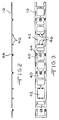
- Fig. 2 is a side elevational view of a ribbon spring according to the present invention;
- Fig. 3 is a plan view of the ribbon spring shown in Fig. 2;
- Fig. 4 is a plan view of a portion of an outer cage according to the present invention;
- Fig. 5 is a side elevational view of a portion of the outer cage shown in Fig. 4;
- Fig. 6 is a cross-sectional view taken through line 6-6 of Fig. 4;
- Fig. 7 is an exploded view of a portion of the sprag and roller one-way clutch assembly according to the present invention; and
- Fig. 8 is a perspective view of a portion of the sprag and roller one-way clutch assembly according to the present invention.
- The preferred embodiments and best mode of the present invention will now be described in detail with reference being made to the drawings. The sprag and roller one-way clutch assembly of the present invention is indicated generally in the drawings by the reference number "10".
- Referring to Figs. 1, 7 and 8, the
assembly 10 includes anouter cage 12, aninner cage 14 and aribbon spring 16. As shown in Figs. 1, 4, 5 and 6, theouter cage 12 has a generally circular configuration. Theouter cage 12 defines a plurality ofsprag openings 20 androller openings 22. As described below, thesprag openings 20 receive sprags and theroller openings 22 receive rollers. As shown in Fig. 6, theroller openings 22 have a cylindricallyshaped wall 24 for receiving a roller. Theouter cage 12 can be made from a variety of materials, with a polymer material being preferred. Fiber reinforcements provide additional strength to the polymer material. It has been found that a fiber glass reinforced nylon is especially suitable for the manufacture of theouter cage 12. This type of material allows theouter cage 12 to be resilient yet flexible enough to move with respect to the sprags and rollers. This is especially important so that theouter cage 12 can engage or "capture" the rollers. - Referring to Figs. 1 and 7, the
inner cage 14 has a generally circular configuration, which corresponds to the configuration of theouter cage 12. Theinner cage 14 defines a plurality ofsprag openings 30 androller openings 32, which correspond to the sprag androller openings outer cage 12. Each of theroller openings 32 defined by theinner cage 14 includes a cylindricallyshaped wall 34 for receiving a roller. Theinner cage 14 can be made from a variety of materials, with an unfilled polymer material being preferred. An unfilled nylon is an especially suitable material for the manufacture of theinner cage 14. Various metals can also be used to manufacture theinner cage 14. - Referring to Figs. 1, 2, 3 and 7, the
ribbon spring 16 of theassembly 10 defines a plurality ofsprag windows 40 androller windows 42. Theribbon spring 16 defines asprag tab 44 in each of thesprag windows 40. Thesprag tabs 44 maintain the sprags in proper position in theassembly 10. Theribbon spring 16 defines a plurality ofroller tabs 46 in each of theroller windows 42. In the present embodiment, there are fourroller tabs 46 in each of theroller windows 42. Theroller tabs 46 are in contact with the rollers to maintain the rollers in proper position in theassembly 10. As shown in Fig. 2, theroller tabs 46 extend inwardly from theribbon spring 16. As shown in Figs. 1 and 7, theribbon spring 16 has a generally circular configuration that corresponds to the circular configurations of the outer andinner cages ribbon spring 16 can be made from a variety of materials, with metal being preferred. - Referring to Figs. 1, 7 and 8, the
assembly 10 includes a plurality of spacedsprags 50 extending between and through thecorresponding sprag openings inner cages sprags 50 extend through thecorresponding sprag windows 40 defined by theribbon spring 16. Thesprags 50 can include a variety of shapes, with the conventional shape shown in the present drawings being preferred. Thesprags 50 can be made from a variety of materials, with metal being preferred. - Still referring to Figs. 1, 7 and 8, the
assembly 10 includes a plurality of spacedrollers 60 extending between and through the correspondingroller openings inner cages rollers 60 are in rolling engagement with the cylindrically shapedwalls roller openings rollers 60 extend through the correspondingroller windows 42 defined by theribbon spring 16. Therollers 60 are in rolling engagement with theroller tabs 46 defined by theribbon spring 16 in theroller windows 42. Each of therollers 60 has a generally cylindrical configuration as shown in the drawings. Therollers 60 can be made from a variety of materials, with metal being preferred. - It should be understood that any number of
sprags 50 can be used with any number ofrollers 60 in theassembly 10 depending on the application for the assembly. However, it has been found that an assembly having sixteensprags 50 and eightrollers 60 is preferred. As shown in Fig. 1, the eightrollers 60 are equally spaced along theassembly 10. Twosprags 50 are positioned between each pair ofrollers 60. - Still referring to Fig. 1, the
assembly 10 is positioned in thespace 74 defined by anouter race 70 and aninner race 72 of a clutch. The outer andinner races inner cages ribbon spring 16. Theinner race 72 can move in the direction indicated by the arrows in Fig. 1. When theinner race 72 moves in the direction indicated by the arrows, theassembly 10 is in a normal freewheel position. Thesprags 50 are each movable between a freewheel position in which the inner cage is free to rotate and a locked position in which the inner cage is restricted in rotation. This restriction in rotation allows the clutch to exert torque. During rotation of theinner race 72, therollers 60 also rotate. Therollers 60 act as bearings to support the outer andinner races rollers 60 control the eccentricities of the outer andinner races - As shown in Fig. 1, lubricating
oil 80 is positioned in thespace 74 defined by the outer andinner races assembly 10. Therollers 60 move or redistribute the lubricatingoil 80 from theouter race 70 to theinner race 72 as therollers 60 move in the direction indicated by the arrows in Fig. 1. This provides for even distribution of the lubricating oil between theraces assembly 10. This ensures superior lubrication of the outer andinner races - The above detailed description of the present invention is given for explanatory purposes. It will be apparent to those skilled in the art that numerous changes and modifications can be made without departing from the scope of the invention. Accordingly, the whole of the foregoing description is to be construed in an illustrative and not a limitative sense, the scope of the invention being defined solely by the appended claims.
Claims (10)
- A sprag and roller one-way clutch assembly (10), comprising:an outer cage (12) and an inner cage (14), each of said cages (12, 14) defining a plurality of corresponding sprag and roller openings (20, 30, 22, 32);a ribbon spring (16) positioned between said outer and inner cages (12, 14), said ribbon spring (16) defining a plurality of corresponding sprag and roller windows (40, 42);a plurality of spaced sprags (50) extending between and through said corresponding sprag openings (20, 30) defined by said outer and inner cages (12, 14) and through said corresponding sprag windows (40) defined by said ribbon spring (16); anda plurality of spaced rollers (60) extending between and through said corresponding roller openings (22, 32) defined by said outer and inner cages (12, 14) and through said corresponding roller windows (42) defined by said ribbon spring (16), each of said rollers (60) having a substantially cylindrical configuration.
- The invention of claim 1, wherein said outer cage (12) consists of a polymer material.
- The invention of claim 2, wherein said polymer material includes fiber reinforcements.
- The invention of claim 1, wherein said inner cage (14) consists of a polymer material.
- The invention of claim 4, wherein said polymer material is unfilled.
- The invention of claim 1, wherein each of said roller openings (22, 32) defined by said outer and inner cages (12, 14) has a wall (24, 34) having a configuration corresponding to said rollers (60).
- The invention of claim 6, wherein said roller openings (22, 32) engage said rollers (60).
- The invention of claim 1, wherein said ribbon spring (16) defines a plurality of roller tabs (46) adjacent each of said roller windows (42).
- The invention of claim 1, wherein said assembly (10) is positioned between an outer race (70) and an inner race (72) adjacent lubricating oil (80), said rollers (60) moving said oil (80) from said outer race (70) to said inner race (72) during rotation of said inner race (72).
- A sprag and roller one-way clutch assembly (10) for use with a clutch having an outer (70) and an inner race (72), comprising:a polymeric outer cage (12) and an inner cage (14), each of said cages (12, 14) defining a plurality of corresponding sprag and roller openings (20, 30, 22, 32), each of said roller openings (22, 32) having a substantially cylindrical configuration;a ribbon spring (16) positioned between said outer and inner cages (12, 14), said ribbon spring (16) defining a plurality of corresponding sprag and roller windows (40, 42), said ribbon spring (16) defining a plurality of roller tabs (46) adjacent each of said roller windows (42);a plurality of spaced sprags (50) extending between and through said corresponding sprag openings (20, 30) defined by said outer and inner cages (12, 14) and through said corresponding sprag windows (40) defined by said ribbon spring (16), each of said sprags (50) being movable between a freewheel position in which at least one of said races (70, 72) is free to rotate and a locked position in which rotation of said races (70, 72) is restricted; anda plurality of spaced substantially cylindrical rollers (60) extending between and through said corresponding roller openings (22, 32) defined by said outer and inner cages (12, 14) and through said corresponding roller windows (42) defined by said ribbon spring (16), each of said rollers (60) being in rolling engagement with said roller tabs (46) defined by said ribbon spring (16), each of said rollers (60) acting as a bearing to support said outer and inner races (70, 72) during rotation.
Applications Claiming Priority (2)
| Application Number | Priority Date | Filing Date | Title |
|---|---|---|---|
| US642644 | 1996-05-03 | ||
| US08/642,644 US5676226A (en) | 1996-05-03 | 1996-05-03 | Sprag and roller one-way clutch assembly |
Publications (1)
| Publication Number | Publication Date |
|---|---|
| EP0806584A1 true EP0806584A1 (en) | 1997-11-12 |
Family
ID=24577433
Family Applications (1)
| Application Number | Title | Priority Date | Filing Date |
|---|---|---|---|
| EP97302555A Withdrawn EP0806584A1 (en) | 1996-05-03 | 1997-04-15 | Sprag and roller one-way clutch assembly |
Country Status (5)
| Country | Link |
|---|---|
| US (1) | US5676226A (en) |
| EP (1) | EP0806584A1 (en) |
| JP (1) | JPH1054427A (en) |
| KR (1) | KR100497263B1 (en) |
| CA (1) | CA2202053C (en) |
Families Citing this family (29)
| Publication number | Priority date | Publication date | Assignee | Title |
|---|---|---|---|---|
| JP3875771B2 (en) * | 1997-08-26 | 2007-01-31 | Nskワーナー株式会社 | One way clutch |
| JPH11218144A (en) * | 1997-11-17 | 1999-08-10 | Nippon Seiko Kk | Rolling bearing with built-in one-way clutch |
| GB2372524B (en) * | 1999-09-17 | 2004-03-10 | Austoil Engineering Services L | Clamping mechanism, clutch and apparatus incorporating the same |
| US20020144575A1 (en) * | 1999-09-17 | 2002-10-10 | David Niven | Gripping or clamping mechanisms |
| JP3652207B2 (en) * | 2000-03-28 | 2005-05-25 | 日本精工株式会社 | One-way clutch built-in type rotation transmission device |
| KR100799792B1 (en) * | 2000-03-28 | 2008-01-31 | 닛뽄 세이꼬 가부시기가이샤 | Rotational transmission with built-in one-way clutch |
| US6640949B1 (en) * | 2001-03-03 | 2003-11-04 | The United States Of America As Represented By The Administrator Of The National Aeronautics And Space Administration | 1-way bearing |
| US6892868B2 (en) * | 2001-07-05 | 2005-05-17 | Koyo Seiko Co., Ltd. | One-way clutch |
| KR100460917B1 (en) * | 2002-11-14 | 2004-12-09 | 현대자동차주식회사 | One way clutch |
| WO2004053350A1 (en) * | 2002-12-10 | 2004-06-24 | Singapore Technologies Kinetics Ltd | A hybrid driving device and clutch/damper mechanism therefor and methods relating thereto |
| US7093703B2 (en) * | 2003-04-23 | 2006-08-22 | Koyo Seiko Co., Ltd. | One-way clutch integrated with a rolling bearing, and method of producing the same |
| JP2005207551A (en) * | 2003-06-06 | 2005-08-04 | Exedy Corp | Frictional resistance generating mechanism |
| KR20050055448A (en) * | 2003-12-08 | 2005-06-13 | 현대자동차주식회사 | Clutch for manual transmission |
| DE102004028669A1 (en) * | 2004-06-12 | 2005-12-29 | Ina-Schaeffler Kg | Overrunning clutch |
| JP2006292140A (en) * | 2005-04-14 | 2006-10-26 | Nsk Warner Kk | Sprag-type one-way clutch |
| KR100809826B1 (en) | 2006-06-07 | 2008-03-04 | 한국보그워너티에스 유한회사 | Sprag type one-way clutch with eccentric bearing block |
| US20130118851A1 (en) * | 2011-11-15 | 2013-05-16 | Schaeffler Technologies AG & Co. KG | Modular sprag clutch cage |
| WO2014094817A1 (en) * | 2012-12-17 | 2014-06-26 | Aktiebolaget Skf | Sprag clutch |
| WO2014179732A2 (en) * | 2013-05-02 | 2014-11-06 | Weatherford/Lamb, Inc. | Tubular handling tool |
| JP2017053453A (en) * | 2015-09-10 | 2017-03-16 | Ntn株式会社 | Sprag type one-way clutch |
| JP2019078308A (en) * | 2017-10-23 | 2019-05-23 | Nskワーナー株式会社 | One-way clutch |
| DE202019106004U1 (en) * | 2019-10-29 | 2021-02-01 | Paul Müller GmbH & Co. KG Unternehmensbeteiligungen | Freewheel element |
| DE102019218785A1 (en) * | 2019-12-03 | 2021-06-10 | Brose Antriebstechnik GmbH & Co. Kommanditgesellschaft, Berlin | Sprag freewheel unit and drive device for an electric bicycle with sprag freewheel unit |
| DE102019133857A1 (en) * | 2019-12-11 | 2021-06-17 | Bayerische Motoren Werke Aktiengesellschaft | Freewheel and freewheel pulley |
| JP2023160177A (en) | 2022-04-21 | 2023-11-02 | 株式会社椿本チエイン | cam clutch |
| DE102022109860B3 (en) * | 2022-04-25 | 2023-01-12 | Ringspann Gmbh | CAGE FREEWHEEL WITH BEARING ROLLERS |
| JP2024085864A (en) * | 2022-12-15 | 2024-06-27 | 株式会社椿本チエイン | Cam clutch unit |
| CN116328992A (en) * | 2023-04-06 | 2023-06-27 | 岚图汽车科技有限公司 | A ball rotary spraying fixture |
| JP7709064B2 (en) * | 2023-07-11 | 2025-07-16 | 株式会社椿本チエイン | Cam clutch unit |
Citations (6)
| Publication number | Priority date | Publication date | Assignee | Title |
|---|---|---|---|---|
| GB781023A (en) * | 1954-06-21 | 1957-08-14 | Borg Warner | Improvements in or relating to one-way engaging device |
| FR2280830A1 (en) * | 1974-08-02 | 1976-02-27 | Zuleger Josef | SECTOR FREEWHEEL COUPLING |
| GB2084671A (en) * | 1980-10-02 | 1982-04-15 | Skf Cie Applic Mecanique | Assembly for forming a freewheel or unidirectional clutch |
| EP0291550A1 (en) * | 1987-05-20 | 1988-11-23 | Borg-Warner Automotive GmbH | Wedging body free-wheel with a double cage |
| WO1991006784A1 (en) * | 1989-10-24 | 1991-05-16 | Rabe Juergen | Process for producing a rolling bearing cage with cast-on spring elements, and rolling bearing cage so produced |
| US5291978A (en) * | 1991-11-05 | 1994-03-08 | Koyo Seiko Co., Ltd. | One way clutch having outer and inner retainers each made of plastics |
Family Cites Families (14)
| Publication number | Priority date | Publication date | Assignee | Title |
|---|---|---|---|---|
| US3049205A (en) * | 1954-06-21 | 1962-08-14 | Borg Warner | One-way clutch and bearing |
| US3886740A (en) * | 1974-06-17 | 1975-06-03 | Gen Motors Corp | Hydrodynamic torque converter with hydraulically energized one-way roller clutch |
| US4130191A (en) * | 1977-08-17 | 1978-12-19 | Borg-Warner Corporation | Sprag clutch assembly |
| FR2458004A1 (en) * | 1979-05-28 | 1980-12-26 | Skf Cie Applic Mecanique | FREE RADIAL RECALL WHEEL |
| US4360093A (en) * | 1979-10-29 | 1982-11-23 | Tsubakimoto-Morse Co., Ltd. | One-way clutch |
| SE8406001L (en) * | 1984-11-28 | 1986-04-14 | Skf Nova Ab | DEVICE WHEEL |
| US4756395A (en) * | 1985-12-03 | 1988-07-12 | Dana Corporation | Overrunning clutch with controlled sprag action |
| JP2555332B2 (en) * | 1986-12-12 | 1996-11-20 | エヌエスケー・ワーナー 株式会社 | One way clutch ribbon spring |
| US5064037A (en) * | 1990-03-01 | 1991-11-12 | Long Jr Thomas F | One-way acting sprag clutch with centrifugal disengagement from the outer race |
| US5176232A (en) * | 1992-01-09 | 1993-01-05 | Borg-Warner Automotive Transmission & Engine Components Corporation | High-speed roller one-way clutch |
| US5183139A (en) * | 1992-01-09 | 1993-02-02 | Borg-Warner Automotive Transmission & Engine Components Corporations | Overrunning clutch having a cage design for directing lube flow |
| JP2574916Y2 (en) * | 1992-08-31 | 1998-06-18 | 光洋精工株式会社 | Spring for one-way clutch |
| US5320204A (en) * | 1993-01-26 | 1994-06-14 | Borg-Warner Automotive, Inc. | One-way clutch |
| DE4311288C1 (en) * | 1993-04-06 | 1994-11-10 | Steyr Daimler Puch Ag | Freewheel dependent on direction of rotation and having a wrap spring |
-
1996
- 1996-05-03 US US08/642,644 patent/US5676226A/en not_active Expired - Lifetime
-
1997
- 1997-04-07 CA CA002202053A patent/CA2202053C/en not_active Expired - Fee Related
- 1997-04-15 EP EP97302555A patent/EP0806584A1/en not_active Withdrawn
- 1997-04-22 JP JP9104663A patent/JPH1054427A/en active Pending
- 1997-05-02 KR KR1019970016997A patent/KR100497263B1/en not_active Expired - Lifetime
Patent Citations (6)
| Publication number | Priority date | Publication date | Assignee | Title |
|---|---|---|---|---|
| GB781023A (en) * | 1954-06-21 | 1957-08-14 | Borg Warner | Improvements in or relating to one-way engaging device |
| FR2280830A1 (en) * | 1974-08-02 | 1976-02-27 | Zuleger Josef | SECTOR FREEWHEEL COUPLING |
| GB2084671A (en) * | 1980-10-02 | 1982-04-15 | Skf Cie Applic Mecanique | Assembly for forming a freewheel or unidirectional clutch |
| EP0291550A1 (en) * | 1987-05-20 | 1988-11-23 | Borg-Warner Automotive GmbH | Wedging body free-wheel with a double cage |
| WO1991006784A1 (en) * | 1989-10-24 | 1991-05-16 | Rabe Juergen | Process for producing a rolling bearing cage with cast-on spring elements, and rolling bearing cage so produced |
| US5291978A (en) * | 1991-11-05 | 1994-03-08 | Koyo Seiko Co., Ltd. | One way clutch having outer and inner retainers each made of plastics |
Also Published As
| Publication number | Publication date |
|---|---|
| CA2202053C (en) | 2005-06-14 |
| US5676226A (en) | 1997-10-14 |
| CA2202053A1 (en) | 1997-11-03 |
| KR100497263B1 (en) | 2005-10-06 |
| JPH1054427A (en) | 1998-02-24 |
| KR970075438A (en) | 1997-12-10 |
Similar Documents
| Publication | Publication Date | Title |
|---|---|---|
| US5676226A (en) | Sprag and roller one-way clutch assembly | |
| JPH0716101Y2 (en) | Fixed structure of thrust roller bearing | |
| EP0447026B1 (en) | Radial spacer and retainer for roller one-way clutch | |
| US6092634A (en) | Compliant cage for a roller-type bi-directional one-way clutch mechanism | |
| US6109410A (en) | Ratchet one-way clutch assembly | |
| US4088211A (en) | Overrunning roller clutch with improved cage and bearing block | |
| US5176232A (en) | High-speed roller one-way clutch | |
| EP0508564A3 (en) | Outer cage for one-way sprag clutch | |
| US4549638A (en) | Roller clutch adjustable force spring mount | |
| KR100476574B1 (en) | Ratchet one-way clutch assembly | |
| US5445255A (en) | Sprag one-way clutch with inertia resistance members | |
| JP4053299B2 (en) | Interlock type linear roller bearing | |
| JPH07117105B2 (en) | Cage for large rolling bearings | |
| US3356428A (en) | Roller bearing cage | |
| US6367982B1 (en) | Cylindrical roller bearing | |
| GB2310009A (en) | Comb cage for rolling bearing | |
| US5908094A (en) | Freewheel assembly | |
| EP0651168B1 (en) | Spherical roller bearing | |
| US5070976A (en) | Sprag retainer | |
| JPH0772567B2 (en) | One-way clutch with end bearing | |
| EP0129270B1 (en) | Sealing ring for a rolling bearing | |
| EP0237243A1 (en) | One-way roller clutch accordion spring with stabilizer | |
| CA2030194A1 (en) | Clutch apparatus | |
| US5558447A (en) | Roller bearing | |
| JPS6120737B2 (en) |
Legal Events
| Date | Code | Title | Description |
|---|---|---|---|
| PUAI | Public reference made under article 153(3) epc to a published international application that has entered the european phase |
Free format text: ORIGINAL CODE: 0009012 |
|
| AK | Designated contracting states |
Kind code of ref document: A1 Designated state(s): DE FR GB |
|
| STAA | Information on the status of an ep patent application or granted ep patent |
Free format text: STATUS: THE APPLICATION HAS BEEN WITHDRAWN |
|
| 17P | Request for examination filed |
Effective date: 19980507 |
|
| 18W | Application withdrawn |
Withdrawal date: 19980515 |