EP1035265A1 - Ensemble d'attache anti-vibrations à deux degrés de liberté - Google Patents
Ensemble d'attache anti-vibrations à deux degrés de liberté Download PDFInfo
- Publication number
- EP1035265A1 EP1035265A1 EP00400633A EP00400633A EP1035265A1 EP 1035265 A1 EP1035265 A1 EP 1035265A1 EP 00400633 A EP00400633 A EP 00400633A EP 00400633 A EP00400633 A EP 00400633A EP 1035265 A1 EP1035265 A1 EP 1035265A1
- Authority
- EP
- European Patent Office
- Prior art keywords
- assembly according
- elastic block
- coupling means
- profile
- attachment
- Prior art date
- Legal status (The legal status is an assumption and is not a legal conclusion. Google has not performed a legal analysis and makes no representation as to the accuracy of the status listed.)
- Granted
Links
- 230000008878 coupling Effects 0.000 claims description 41
- 238000010168 coupling process Methods 0.000 claims description 41
- 238000005859 coupling reaction Methods 0.000 claims description 41
- 239000013013 elastic material Substances 0.000 claims description 5
- 210000000056 organ Anatomy 0.000 claims 1
- 230000000712 assembly Effects 0.000 abstract 1
- 238000000429 assembly Methods 0.000 abstract 1
- 229940082150 encore Drugs 0.000 description 3
- 238000005192 partition Methods 0.000 description 3
- 239000002184 metal Substances 0.000 description 2
- 230000002093 peripheral effect Effects 0.000 description 2
- 208000031968 Cadaver Diseases 0.000 description 1
- 239000004568 cement Substances 0.000 description 1
- 238000010276 construction Methods 0.000 description 1
- 230000000694 effects Effects 0.000 description 1
- 238000009434 installation Methods 0.000 description 1
- 238000012423 maintenance Methods 0.000 description 1
- 239000000463 material Substances 0.000 description 1
- 238000010079 rubber tapping Methods 0.000 description 1
- 238000000926 separation method Methods 0.000 description 1
Images




Classifications
-
- F—MECHANICAL ENGINEERING; LIGHTING; HEATING; WEAPONS; BLASTING
- F16—ENGINEERING ELEMENTS AND UNITS; GENERAL MEASURES FOR PRODUCING AND MAINTAINING EFFECTIVE FUNCTIONING OF MACHINES OR INSTALLATIONS; THERMAL INSULATION IN GENERAL
- F16L—PIPES; JOINTS OR FITTINGS FOR PIPES; SUPPORTS FOR PIPES, CABLES OR PROTECTIVE TUBING; MEANS FOR THERMAL INSULATION IN GENERAL
- F16L55/00—Devices or appurtenances for use in, or in connection with, pipes or pipe systems
- F16L55/02—Energy absorbers; Noise absorbers
- F16L55/033—Noise absorbers
- F16L55/035—Noise absorbers in the form of specially adapted hangers or supports
-
- E—FIXED CONSTRUCTIONS
- E04—BUILDING
- E04B—GENERAL BUILDING CONSTRUCTIONS; WALLS, e.g. PARTITIONS; ROOFS; FLOORS; CEILINGS; INSULATION OR OTHER PROTECTION OF BUILDINGS
- E04B9/00—Ceilings; Construction of ceilings, e.g. false ceilings; Ceiling construction with regard to insulation
- E04B9/18—Means for suspending the supporting construction
- E04B9/20—Means for suspending the supporting construction adjustable
-
- E—FIXED CONSTRUCTIONS
- E04—BUILDING
- E04B—GENERAL BUILDING CONSTRUCTIONS; WALLS, e.g. PARTITIONS; ROOFS; FLOORS; CEILINGS; INSULATION OR OTHER PROTECTION OF BUILDINGS
- E04B9/00—Ceilings; Construction of ceilings, e.g. false ceilings; Ceiling construction with regard to insulation
- E04B9/18—Means for suspending the supporting construction
- E04B2009/186—Means for suspending the supporting construction with arrangements for damping vibration
Definitions
- the present invention relates to an anti-vibration attachment assembly.
- the attachment assembly is then a set of anti-vibration hanger intended to suspend an element carried from an element load-bearing, such as for example a suspended ceiling with a load-bearing structure than a cement slab or a roof, or other, more generally in the construction or fitting out of premises.
- an element load-bearing such as for example a suspended ceiling with a load-bearing structure than a cement slab or a roof, or other, more generally in the construction or fitting out of premises.
- carrier and “carried” even if one does not carry the other, as can be the case when they are placed side by side, and not one above the other.
- Such an assembly generally comprises an elastic block provided with two spans at a distance from each other which each cooperate with a coupling means for coupling the assembly, on the one hand, to the load-bearing element and, on the other hand, to the element carried.
- the object of the present invention is to propose a hanger assembly of the above type which is simple, easily adjustable in two degrees of freedom, in height and angle, and whose implementation is easy, the attachment assembly practically constituting in itself an attachment of a single piece.
- an anti-vibration attachment assembly intended to connect a so-called element worn to a so-called carrier element, comprising an elastic block, consisting of at least one block of elastic material, provided with two bearing surfaces distance from each other, these scopes each cooperating with a means coupling to couple the assembly, on the one hand, to the carrier element and, on the other part, to the element carried, is characterized by the fact that one of the means coupling said first coupling means consists of a member called carrier cooperating with one of the spans of the elastic block called the first span and internally carrying a thread with which is adapted to cooperate a threaded rod can be attached to one of the supporting and carried elements, the other means said second coupling means consisting of a body having at least a portion of cylindrical rail cooperating with the other so-called bearing second bearing surface of the elastic block, said body further comprising attachment means by which it is coupled to the other of the elements carried and carrier.
- the first bearing surface of the elastic block is a flat face external it presents and into which opens a central well which crosses the elastic block, the member carrying the first coupling means being in disc shape and integral with a tube internally provided with a thread to receive the threaded rod.
- the tube carries, in the vicinity of its end opposite to that by which it is secured to the carrier member, a flange intended to immobilize the tube axially with respect to the elastic block.
- the first bearing surface of the elastic block is the directed face towards the inside of a transverse passage which comprises the elastic block and in which the carrier of the first means is introduced transversely coupling, the thread carried by said carrier member being at the right of a central well which passes through the elastic block and which is adapted to receive the rod threaded.
- the transverse passage is of general shape parallelepiped and the carrier member is a plate; alternatively, the passage transverse is generally cylindrical and the carrier member is a socket.
- the second span of the block elastic consists of two half-seconds worn placed laterally on either side of the elastic block, the body of the second coupling means having two rail portions, each cooperating half-second bearing each with a portion of rail; the body of the second coupling means includes two flanges having cylindrical edges facing one of the other each constituting a portion of rail; alternatively, the body of the second coupling means comprises two flanges having flanges frustoconical opposite one another each constituting a portion of rail.
- each edge extends at an angle greater than 180 degrees, advantageously of the order of 280 degrees.
- the body of the second coupling means comprises two flanges, the outer edges of which each constitute a portion of rail.
- each half second worn is the external face lateral ends of a support plate supported by the block elastic ; the support plate present laterally, at the right of each half second carried, at least two pins parallel to and at a distance from said half second span thanks to which the elastic block is guided and supported by the body of the second coupling means.
- each half-second carried is the external face of the lateral ends of the elastic block.
- each half second worn on one side a lateral groove formed in the elastic block.
- the elastic block is in the form of a sector; he can be of parallelepiped shape, or of cylindrical shape.
- the elastic block is in one piece; in variant, it is in two pieces.
- the body of the second coupling means is shaped general of a U whose wings are constituted by the flanges and whose soul carries the means for hooking the hanger element.
- the attachment means are arranged to cooperate with a profile, for example I-shaped and include two pairs of legs each pair of which has two legs facing each other, intended for overlap the edges of the profile wing.
- the body is also adapted to receive the soul a U-shaped attachment adapter, the wings of which are cut so as to be able to adapt to one of the U-shaped wings of an omega profile.
- the attachment means are arranged to cooperate with a wing of a profile, for example I-shaped, and include two tabs intended to overlap each edge of the profile wing, both legs being at a distance from each other at least equal to the width of the wing of the profile so that the overlap is obtained by rotation of the body relative to the profile.
- the means for attaching the body are arranged to cooperate with an omega-shaped profile and include two wings cut so that it can be adapted to one of the U-shaped wings of the profile.
- the body is in one piece; alternatively it is in two pieces.
- the present invention also relates to an elastic block, a carrier member and a body for hanger such as those of the above assembly.
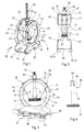
- a set of fasteners anti-vibration with two degrees of freedom includes a block of material elastic 10, a first coupling means 30 and a second coupling means 40.
- the elastic block 10 is in the general shape of a circular sector and is crossed radially by a central well 11 which opens into one face external plane 12 which limits the elastic block 10 opposite its external face cylindrical 13, which cylindrical face 13 is covered with a plate 20 metal support supported by the elastic block 10.
- the first coupling means 30 consists of a support member 31, here in the form of a disc, integral with a tube 32 provided internally with a internal thread 33.
- the second coupling means 40 consists of a body 41 having the general shape of a U whose wings each consist of a flange 42, 43 each having a circular central opening 44, 45 respectively ; each of the flanges 42, 43 is provided with a rim cylindrical 46, 47 respectively; the two flanges 46, 47 extend here generally perpendicular to the plane of the flanges 42, 43 being internally directed towards each other; they extend circumferentially over 180 degrees, in any case less than 360 degrees so that at vicinity of the connection of the flanges 42, 43 to the core 48 of the body 41 in a U there is no ledge.
- the core 48 of the U-shaped body 41 carries hooking means which here include two pairs of legs 51, 52 from a cutting of soul 48; the legs 51, 52 are offset outwardly extending parallel to the core 48; each pair 51, 52 of legs includes two legs which face each other intended to overlap the edges of the wing 81 of a profile 80, Figure 2, the wing 81 of profile 80 having its edges which extend between the legs 51, 52 and the core 48 of the body 41; profile 80 is better visible in Figure 5 where it is partially shown in perspective. Thanks in this arrangement, it is easy to mount the body 41 on such a profile 80.
- the carrier member 31 of the first coupling means 30 cooperates with a first bearing surface of the elastic block 10 formed here by the flat face outer 12 of elastic block 10.
- the body 41 of the second coupling means 40 cooperates with a second reach of the elastic block 10: more precisely, this second litter consists of two half-seconds litter placed laterally on either side of the elastic block 10 and each formed by the face external of the lateral ends 21, 22 which border the support plate 20, which covers the cylindrical external face 13 of the elastic block 10.
- the thickness measured laterally of the elastic block 10 is of the order of magnitude of the distance which separates, in this direction, the flanges 42, 43 of the body 41 so that when the elastic block 10 is introduced between the flanges 42, 43 thanks to the openings 44, 45 dimensioned in consequently, this second bearing cooperates with the internal face of the flanges 46, 47 cylindrical of said flanges 42, 43.
- a threaded rod 70 is introduced into the tube 32 of the first means coupling 30, cooperating with the thread 33 which it has.
- the attachment assembly according to the invention which has just been described, is used as follows.
- the assembly is shown in a position for which the threaded rod 70 emerges at the top of the assembly, the core of which 48 of the body 41 is in the lower part and generally perpendicular to the rod threaded 70; thus, the threaded rod can be coupled, by any suitable means, to a carrier element, the element carried here being the profile 80; by cooperation of the ranges described above, the section 70 is resiliently suspended from the carrier element; by turning the disk-shaped carrier member 31, of which the outer surface can be knurled, as shown, to facilitate this operation, we see that we can adjust the height of the profile 80 relative to the carrier element; moreover, by rotating the body 41 relative to the block elastic 10, thanks to the cylindrical rail portions 46 and 47, it is possible tilt the profile 80 at will relative to the threaded rod 70, as shown in phantom in Figure 2.
- the attachment assembly here of hanger
- the attachment assembly is compact, simple to carry out and easy to implement, thanks in particular to its two degrees of freedom, in height and angle.
- the block can be supported elastic 10 by the body 41; to do this, and as shown in the figures, the support plate 20 has laterally, in line with each half second worn 21 and 22, pins 23, here two pairs lugs, obtained by cutting and deforming the edges of the support plate 20, extending outwardly away from it so that they partially cover the cylindrical edges 46, 47 of the body 41, preferably being parallel to them: thus, the elastic block 10 is guided and supported by the body 40; for the establishment of the elastic block 10, it sufficient, after having introduced it through one of the openings 44 or 45 and placed between the flanges 42 and 43, to put it in the opposite position to that shown, pins 23 close to the core 48 of the body 41, and to do so turn about 180 degrees making sure to introduce the ends of the flanges 46 and 47 under the lugs 23. This is possible due to the fact that the ledges 46 and 47 do not extend 360 degrees but are interrupted at the vicinity of the core 48 of the body 41.
- the elastic block 10 has at its ends, longitudinal projections 14, 15 around which are folded the longitudinal edges 24, 25 of the support plate 20.
- the support plate 20 can be omitted; so according to a variant not shown, the elastic block 10 cooperates directly, by its cylindrical outer face 13, with the cylindrical edges 46, 47 of the body 41 and each half second worn is the lateral end of this face external 13.
- the block elastic 10 has on its lateral faces cylindrical grooves in which engage the cylindrical edges 46, 47 of the body 41, each half-second bearing being constituted by an internal face of a groove, the lower internal face when the hanger assembly is arranged so similar to that shown in Figures 1 to 3.
- FIG. 5 shows a variant of hanging means arranged in the soul 148 of the body 141; according to this variant, they consist of two legs 151, 152 similar to legs 51, 52 of the previous variant and also intended, each, to overlap one edge of the wing 81 of the profile 80 in the shape of an I; the two legs 151, 152 do not face each other to each other but are offset from each other by being one distance 153 at least equal to the width 82 of the wing 81 of the profile 80; thanks in this arrangement, the overlapping attachment is obtained by rotation of the body 141 relative to the profile 80; for body maintenance 141 by relative to the profile 80 in this hooking position, the legs 151, 152 are extended by returns 154, 155 secured to the core 83 of the profile 80, for example by screwing.
- the supporting or worn element is an omega 90 profile, figure 6, instead of an I-shaped section, the same body 41 or 141 can be used; so, as visible in figure 6, it is enough to associate to said body an adapter attachment type 93.
- the adapter 93 is shaped general of U whose core 94 is placed inside the body 41 on the core 48 of said body; to facilitate handling, the core 94 of the adapter 93 is held against the core 48 of the body 41 by snap-fastening, thanks to lugs 49 provided on the flanges 42, 43 of the body 41 at an appropriate height.
- the wings 95 of adapter 93 are cut to fit the sectional profile of wing 91 in U of profile 90 in omega.
- a tongue 96 is provided, the width of which is at least equal to the height of the rim 97 at right angles to the wing 91 in U of the profile 90 so that this rim 97 can be inserted into the cutout 99 and then lowered into a slot 98 that has the wings 95 of the adapter 93 and which extends perpendicular to the cutout 99 into which it opens; for this positioning operation, the tongue 96 is folded perpendicular to wing 95; then simply fold it in the plane of the wing 95, as shown in phantom in the figure, to immobilize the adapter 93 by compared to profile 90.
- the hanger assembly shown in Figure 7 includes a body 241 similar to the bodies 41 and 141 above except that the two flanges 242 and 243 are connected by two wings 295 cut out to adapt to the sectional profile of the U-shaped wing 91 of the profile 90 in the form of omega and similar to the wings 95 of the adapter 93 of FIG. 6.
- the elastic block 10 is sector-shaped; according to the variant of FIG. 8, the block elastic 100 is of generally parallelepiped shape; here the second scope of the elastic block 100 is constituted by the lateral edges, advantageously rounded, of the elastic block, which extend along the width of said block at its upper part, with respect to the figures, or, as represented by the corresponding edges 113 of a support plate 120 which covers the upper part of the elastic block 100; the support plate 120 also includes lugs 123 similar to lugs 23 previously described.
- the elastic block 120 can cooperate with any body of the second coupling means, such as bodies 41, 141 or 241 previous variants.
- Figure 9 shows a variant of elastic block made in two strictly identical parts; each half-block 201 of the elastic block 200, here of generally parallelepipedal shape, comprises an envelope 220 metal covering four sides of a block of elastic material 203, with know a large face called rear and the three faces adjacent to the face rear: one upper and two lateral.
- the envelope 220 has two lugs 223 at the upper part, similar to the pins 123 of Figure 8; on both sides laterally opposite, the envelope 220 has, on the one hand, a straight edge 204 and, on the other hand, a U-folded rim referenced 205 defining a groove open inwards arranged in the same plane as the straight edge 204 so that it is adapted to receive the straight edge 204 of the other half-block 201 when the two half-blocks 201, presented face to face head to tail first slightly offset, are then placed in coincidence, like this is illustrated in Figure 10.
- each half-block 201 has centrally, on its large face, called the front face, not covered by the envelope 220, a semi-cylindrical groove 211 extending over its entire height parallel to the right and folded edges 204 and 205 and constituting a central half-well.
- Each half-block 201 also has, in the vicinity of its part lower, a through passage 212 extending transversely by relative to the groove 211 and of generally rectangular section; both passages 212 of the half-blocks 201 are intended to receive a carrier member 231, here in the form of a rectangular plate, pierced centrally with a thread 233 for cooperation with the threaded rod 70.
- first bearing of the elastic block 200 is ensured by the upper face of passage 212, and its second bearing is constituted by the lateral edges 213 of the envelopes 220 which are similar to the edges 113 of the elastic block 100 of FIG. 8.
- the support member 231 can be made in the form of a disc with a diameter greater than the thickness of the block elastic 200 assembled so that it can be turned from the outside of the elastic block 200.
- Figure 11 shows in perspective another overall variant of attachment according to the invention.
- each half-body 340 comprises a flange 342 having a flange 346, here frustoconical, constituting the rail portion and a half-core 348 extended downward, relative to the figure, by a wall 355 extending to outward right angle to the half-core 348; wall 355 door laterally on one side a straight edge and on the other side a folded edge 356 similar to the folded edge 205 of the envelope 220 of the previous variant in so that the two half-bodies 340 are assembled in the same way as that described with regard to the two half-blocks 201 of the previous variant; to lock them in position, a key 357 is inserted into a central well constituted by the coincidence of two half-wells, each is obtained by deformation of the wall 355 and of the half-wing 348.
- the wall 355 is extended externally, downwards, by a fold 358, generally parallel to the half-core 348 and from which two legs 351 originate fixing located in the plane of the wall 355; the legs 351 allow the fixing the second coupling means 341, for example by screws self-tapping 359, with the carrier or carried element.
- the elastic block 300 is here also in two parts; each half block 301 of elastic material is of annular shape; the two half blocks 301 are crossed transversely at their center by a socket 331 constituting the carrier member and provided with a diametrical thread for receiving the threaded rod 70.
- this attachment assembly follows from the description above. We will appreciate that, thanks to the frustoconical shape ledges 346, this assembly can support heavy loads without risk spacing of the two flanges 342.
- the half-blocks 301 can cooperate directly with the flanges 346; in the variant shown, a semi-cylindrical support plate 320, is interposed.
- a key 357 locks the two half-bodies 340 in position; alternatively, the threaded rod 70 is provided long enough to be able to play this role.
- the elastic block 400 of shape general cylindrical is axially crossed by the threaded rod 70 and cooperates, on one side, with the support member 431 in the form of a washer associated with a nut 433 screwed onto the threaded rod 70 and, on the other side, with a plate support 420 stapled to the elastic block 400: for this purpose, the elastic block 400 is extended by a cylindrical collar 401, as visible in the figure 17, crossed by the rod 70 and bordered by a flange 402, the support plate 420 therefore being held axially between the external face of the block elastic 400 proper and said collar 402.
- the body 441, in general U-shape, of the second coupling means 440, has flanges 442, 443 whose outer edge itself constitutes the portion of cylindrical rail 446, 447.
- the soul 448 of the body 441 in a U carries two legs 451 which here each extend over a good part of the length of the core 448.
- Ribs 462, 463 formed transversely to the junction line of the legs 451 and the flanges 442, 443 stiffen the body 441.
- the plate support 420 has laterally lugs 423, here two pairs of lugs, obtained by cutting and folding the edges 427 of the support plate 420; these lugs 423 partially close a slot 426 formed on the edge edges 427 and in which the peripheral parts take place crown shape of the flanges 442, 443 including the rail portions 446, 447 cooperate with said lugs 423.
- the positioning of the support plate 420 is carried out by making take advantage of the flexibility of the flanges 442, 443 which, at first, are separated from each other to introduce between them the support plate 420 to the right of the central openings of the flanges 442, 443; in one second time, the support plate 420 is moved to introduce the parts peripherals of the flanges 442, 443 in said slots 426.
- Figures 13 to 15 show a variant in which the plate support 420, shown alone, without the elastic block which it supports, does not differs from the previous one only in that the shorter edges 427, extend in the plane of the plate itself.
- the body 441 represented in FIGS. 16 and 17 is similar to that Figures 12 to 15 but does not have ribs 462,463.
- the support plate 420 is entirely flat, the slots 426 and the edges 424 all being in the same plan, that of the plate itself.
- the fastening assembly has been shown in a position corresponding to use as a hanger; of course, a such an assembly can be used to connect two elements not arranged one to the above each other.
- FIG. 21 schematically illustrates such an application.
- a profile 90 with an omega section, arranged overall vertically, supports a first partition while a profile 85, to C-shaped section, arranged generally horizontally, supports a second partition;
- the elastic block 300 is of the kind of that of FIG. 11;
- the threaded rod 70 is arranged horizontally and cooperates with a socket 331 provided with a diametric thread;
- the body 541 is U-shaped: the wings of the U are of adjustable length and the core of the U, cylindrical, has a longitudinal opening in its area median, crossed by the threaded rod 70, and defining two rail portions cylindrical 546, 547; an adapter 560 makes it possible to connect the threaded rod 70 to profile 85.
Landscapes
- Engineering & Computer Science (AREA)
- Architecture (AREA)
- General Engineering & Computer Science (AREA)
- Civil Engineering (AREA)
- Physics & Mathematics (AREA)
- Electromagnetism (AREA)
- Mechanical Engineering (AREA)
- Structural Engineering (AREA)
- Springs (AREA)
- Connection Of Plates (AREA)
- Vibration Prevention Devices (AREA)
- Fittings On The Vehicle Exterior For Carrying Loads, And Devices For Holding Or Mounting Articles (AREA)
- Holders For Apparel And Elements Relating To Apparel (AREA)
Abstract
Description
- la figure 1 est une vue en perspective d'un ensemble d'attache selon l'invention, en forme d'ensemble de suspente ;
- la figure 2 est une vue selon la flèche II de la figure 1 ;
- la figure 3 est une vue selon la flèche III de la figure 1 ;
- la figure 4 est une vue représentant le tube seul de l'ensemble des figures 1 à 3 ;
- la figure 5 est analogue à la figure 1 et montre une variante de moyens d'accrochage ;
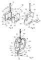
- la figure 6 est analogue à la figure 1 et montre une variante dans laquelle les moyens d'accrochage sont portés par un adaptateur ;
- la figure 7 est analogue à la figure 1 et montre une autre variante de moyens d'accrochage ;
- la figure 8 est une vue partielle analogue à la figure 2 montrant une variante de bloc élastique ;
- la figure 9 est une vue partielle éclatée montrant encore une variante ;
- la figure 10 illustre l'assemblage des deux demi-blocs de la figure 9 ;
- la figure 11 est une vue analogue à la figure 1 montrant encore une autre variante d'un ensemble selon l'invention ;
- la figure 12 est une vue en perspective analogue à la figure 1 et représentant une variante ;
- les figures 13 à 15 montrent une variante de plaque d'appui, la figure 14 étant une vue selon la flèche XIV de la figure 15 elle-même une vue selon la flèche XV de la figure 13 ;
- les figures 16 et 17 montrent une variante du corps du second moyen d'attelage, la figure 17 étant une vue selon la flèche XVII de la figure 16, le bloc élastique ayant été rajouté ;
- les figures 18 à 20 montrent encore une variante de plaque d'appui, ici entièrement plane, le bloc élastique qu'elle supporte ayant été dessiné sur la figure 19 qui est une vue latérale de la figure 18, la plaque d'appui ayant été représentée seule, vue de dessus, sur la figure 20 ;
- la figure 21 est une vue schématique éclatée en perspective montrant l'application de l'invention à la liaison de deux cloisons globalement verticales.
Claims (32)
- Ensemble d'attache anti-vibrations destiné à relier un élément dit porté à un élément dit porteur, comportant un bloc élastique (10,100,200,300, 400), constitué d'au moins un bloc de matière élastique, muni de deux portées (12,13,113) à distance l'une de l'autre, ces portées (12,13,113) coopérant chacune avec un moyen d'attelage (30,40) pour atteler l'ensemble, d'une part, à l'élément porteur et, d'autre part, à l'élément porté, caractérisé par le fait que l'un des moyens d'attelage (30) dit premier moyen d'attelage est constitué d'un organe dit porteur (31,231,331,431) coopérant avec l'une des portées (12) du bloc élastique (10,100,200,300,400) dite première portée et portant intérieurement un taraudage (33,233) avec lequel est adaptée à coopérer une tige filetée (70) attelable à l'un des éléments porteur et porté, l'autre moyen d'attelage (40) dit second moyen d'attelage étant constitué d'un corps (41,141,241,341,441,541) présentant au moins une portion de rail cylindrique (46,47,446,447,546,547) coopérant avec l'autre portée (13,113) dite seconde portée du bloc élastique (10,100,200,300), ledit corps (41,141,241,341,441,541) comportant en outre des moyens d'accrochage (51,151,351,52,152,451) par lesquels il est attelé à l'autre des éléments porté et porteur.
- Ensemble d'attache selon la revendication 1, caractérisé par le fait que la première portée (12) du bloc élastique (10) est une face plane externe qu'il présente et dans laquelle débouche un puits central (11) qui traverse le bloc élastique (10,100), l'organe porteur (31) du premier moyen d'attelage (30) étant en forme de disque et solidaire d'un tube (32) muni intérieurement d'un taraudage (33) pour recevoir la tige filetée (70).
- Ensemble d'attache selon la revendication 2, caractérisé par le fait que le tube (32) porte, au voisinage de son extrémité opposée à celle par laquelle il est solidarisé à l'organe porteur (31), une collerette (34) destinée à immobiliser axialement le tube (32) par rapport au bloc élastique (10,100).
- Ensemble d'attache selon la revendication 1, caractérisé par le fait que la première portée du bloc élastique (200,300) est la face dirigée vers l'intérieur d'un passage transversal (212) que comprend le bloc élastique (200,300) et dans lequel est introduit transversalement l'organe porteur (231,331) du premier moyen d'attelage, le taraudage (233) porté par ledit organe porteur (231,331) étant au droit d'un puits central (211) qui traverse le bloc élastique (200,300) et qui est adapté à recevoir la tige filetée (70).
- Ensemble d'attache selon la revendication 4, caractérisé par le fait que le passage transversal (212) est de forme générale parallélépipédique et l'organe porteur (231) est une plaque.
- Ensemble d'attache selon la revendication 4, caractérisé par le fait que le passage transversal est de forme générale cylindrique et l'organe porteur (331) est une douille.
- Ensemble d'attache selon l'une des revendications 1 à 6, caractérisé par le fait que la seconde portée du bloc élastique (10,100,200,300,400) est constituée de deux demi-secondes portées placées latéralement de part et d'autre du bloc élastique (10,100,200,300,400), le corps (41,141,241,341,441) du second moyen d'attelage (40) présentant deux portions de rail, chaque demi-seconde portée coopérant chacune avec une portion de rail.
- Ensemble d'attache selon la revendication 7, caractérisé par le fait que le corps (41,141,241) du second moyen d'attelage (40) comprend deux flasques (42,43,242,243) ayant des rebords cylindriques (46,47) en regard l'un de l'autre constituant chacun une portion de rail.
- Ensemble d'attache selon la revendication 7, caractérisé par le fait que le corps (341) du second moyen d'attelage comprend deux flasques (342) ayant des rebords tronconiques (346) en regard l'un de l'autre constituant chacun une portion de rail.
- Ensemble d'attache selon l'une des revendications 8 ou 9, caractérisé par le fait que chaque rebord (46,47,346) s'étend selon un angle supérieur à 180 degrés, avantageusement de l'ordre de 280 degrés.
- Ensemble d'attache selon la revendication 7, caractérisé par le fait que le corps (441) du second moyen d'attelage comprend deux flasques (442,443) dont les tranches externes constituent chacune une portion de rail.
- Ensemble d'attache selon l'une des revendications 7 à 11, caractérisé par le fait que chaque demi-seconde portée est la face externe des extrémités latérales d'une plaque d'appui (20,120,220,320,420) supportée par le bloc élastique (10,100,200,300).
- Ensemble d'attache selon la revendication 12, caractérisé par le fait que la plaque d'appui (20,120,220) présente latéralement, au droit de chaque demi-seconde portée, au moins deux ergots (23,123,223,423) parallèles à et à distance de ladite demi-seconde portée grâce auxquels le bloc élastique (10,100,200,400) est guidé et supporté par le corps (41,141,241,441) du second moyen d'attelage.
- Ensemble d'attache selon l'une des revendications 7 à 11, caractérisé par le fait que chaque demi-seconde portée est la face externe des extrémités latérales du bloc élastique (10,100,200).
- Ensemble d'attache selon l'une des revendications 7 à 11, caractérisé par le fait que chaque demi-seconde portée est une face d'une rainure latérale ménagée dans le bloc élastique.
- Ensemble d'attache selon l'une des revendications 7 à 15, caractérisé par le fait que le bloc élastique (10) est en forme de secteur.
- Ensemble d'attache selon l'une des revendications 7 à 15, caractérisé par le fait que le bloc élastique (100,200) est de forme parallélépipédique.
- Ensemble d'attache selon l'une des revendications 7 à 15, caractérisé par le fait que le bloc élastique (300) est de forme cylindrique.
- Ensemble d'attache selon l'une des revendications 7 à 18, caractérisé par le fait que le bloc élastique (10,100) est en une seule pièce.
- Ensemble d'attache selon l'une des revendications 7 à 18, caractérisé par le fait que le bloc élastique (200,300) est en deux pièces.
- Ensemble d'attache selon l'une des revendications 8 à 20, caractérisé par le fait que le corps (41,141) du second moyen d'attelage (40) est en forme générale d'un U dont les ailes sont constituées par les flasques (42,43,342) et dont l'âme (48,348) porte les moyens d'accrochage (51,52,152,154,351) de l'ensemble de suspente.
- Ensemble d'attache selon la revendication 21, caractérisé par le fait que les moyens d'accrochage sont agencés pour coopérer avec un profilé, par exemple en forme de I et comprennent deux paires de pattes (51,52), dont chaque paire comprend deux pattes se faisant face, destinées à chevaucher les bords de l'aile (81) du profilé (80).
- Ensemble d'attache selon la revendication 22, caractérisé par le fait que le corps (41) est également adapté à recevoir l'âme d'un adaptateur d'accrochage (93) en U dont les ailes (95) sont découpées en sorte de pouvoir s'adapter à l'une (91) des ailes en U d'un profilé en oméga (90).
- Ensemble d'attache selon la revendication 21, caractérisé par le fait que les moyens d'accrochage sont agencés pour coopérer avec une aile (81) d'un profilé (80), par exemple en forme de I, et comprennent deux pattes (154,155) destinées à chevaucher chacune un bord de l'aile (81) du profilé (80), les deux pattes étant à une distance (153) l'une de l'autre au moins égale à la largeur (82) de l'aile (81) du profilé (80) en sorte que le chevauchement est obtenu par rotation du corps (141) par rapport au profilé (80).
- Ensemble d'attache selon la revendication 21, caractérisé par le fait que les moyens d'accrochage du corps (241) sont agencés pour coopérer avec un profilé (90) en forme de oméga et comprennent deux ailes (295) découpées en sorte de pouvoir s'adapter à l'une (91) des ailes en U du profilé (90) .
- Ensemble d'attache selon l'une des revendications 21 à 25, caractérisé par le fait que le corps (41,141,241) est d'une seule pièce.
- Ensemble d'attache selon l'une des revendications 21 à 25, caractérisé par le fait que le corps (341) est en deux pièces (340).
- Ensemble d'attache selon la revendication 27, caractérisé par le fait que les deux pièces (340) sont identiques et emboítées l'une dans l'autre, leur position d'emboítement étant verrouillée par une clavette (357).
- Ensemble d'attache selon la revendication 27, caractérisé par le fait que les deux pièces (340) sont identiques et emboítées l'une dans l'autre, leur position d'emboítement étant verrouillée par la tige filetée (70).
- Bloc élastique pour ensemble d'attache selon l'une des revendications 1 à 29, caractérisé par le fait qu'il est en forme de secteur et est muni d'une première portée (12), constituée par une face plane externe qu'il présente, et d'une seconde portée constituée de deux demi-secondes portées placées latéralement de part et d'autre du bloc élastique (10), chacune étant la face externe des extrémités latérales d'une plaque d'appui (20) supportée par le bloc élastique (10) et présentant au moins deux ergots (23), ledit bloc élastique (10) étant traversé par un puits central (11) qui débouche dans la première portée (12).
- Organe porteur pour ensemble d'attache selon l'une des revendications 1 à 29, caractérisé par le fait qu'il est en forme de disque (31) et solidaire d'un tube (32) muni intérieurement d'un taraudage (33) adapté à recevoir la tige filetée (70).
- Corps pour ensemble d'attache selon l'une des revendications 1 à 29, caractérisé par le fait qu'il est en forme générale de U dont les ailes sont constituées par deux flasques (42) ayant des rebords cylindriques (46) en regard l'un de l'autre, et dont l'âme (48) porte les moyens d'accrochage (51,52).
Applications Claiming Priority (2)
| Application Number | Priority Date | Filing Date | Title |
|---|---|---|---|
| FR9902885A FR2790775B1 (fr) | 1999-03-09 | 1999-03-09 | Ensemble de suspente anti-vibrations a deux degres de liberte comportant un bloc elastique, un organe porteur et un corps, et bloc elastique, organe porteur et corps pour un tel ensemble |
| FR9902885 | 1999-03-09 |
Publications (2)
| Publication Number | Publication Date |
|---|---|
| EP1035265A1 true EP1035265A1 (fr) | 2000-09-13 |
| EP1035265B1 EP1035265B1 (fr) | 2005-11-09 |
Family
ID=9542973
Family Applications (1)
| Application Number | Title | Priority Date | Filing Date |
|---|---|---|---|
| EP00400633A Expired - Lifetime EP1035265B1 (fr) | 1999-03-09 | 2000-03-08 | Ensemble d'attache anti-vibrations à deux degrés de liberté |
Country Status (4)
| Country | Link |
|---|---|
| EP (1) | EP1035265B1 (fr) |
| AT (1) | ATE309425T1 (fr) |
| DE (1) | DE60023771D1 (fr) |
| FR (1) | FR2790775B1 (fr) |
Cited By (4)
| Publication number | Priority date | Publication date | Assignee | Title |
|---|---|---|---|---|
| FR2800771A1 (fr) * | 1999-11-04 | 2001-05-11 | Maiztarkoetxea S L | Dispositif de suspension elastique de profiles pour faux plafonds |
| DE102006022903A1 (de) * | 2006-05-15 | 2007-11-22 | Wobatech Ag | Mediendecke für Labors sowie Verfahren zur Montage einer solchen |
| WO2019106116A1 (fr) * | 2017-11-29 | 2019-06-06 | James Dunne | Supports de cloison d'isolation acoustique et système de support de cloison d'isolation acoustique et procédé de construction d'une cloison isolée acoustiquement |
| FR3078352A1 (fr) * | 2018-02-26 | 2019-08-30 | Accessoires Concept | Clip a rotation s'accouplant a tous elements de suspension et de fixation pour plafonds et rampants concus pour le recevoir permettant un support a geometrie variable dans le domaine du batiment |
Citations (3)
| Publication number | Priority date | Publication date | Assignee | Title |
|---|---|---|---|---|
| GB1149757A (en) * | 1965-03-29 | 1969-04-23 | Aero Motive Mfg Company | Clamp structure |
| FR2099008A5 (fr) * | 1970-07-31 | 1972-03-10 | Arichiello Jean | |
| FR2327475A1 (fr) * | 1973-12-12 | 1977-05-06 | Sacatec Caoutchouc Tech | Plot de suspension pour canalisation |
-
1999
- 1999-03-09 FR FR9902885A patent/FR2790775B1/fr not_active Expired - Fee Related
-
2000
- 2000-03-08 AT AT00400633T patent/ATE309425T1/de not_active IP Right Cessation
- 2000-03-08 EP EP00400633A patent/EP1035265B1/fr not_active Expired - Lifetime
- 2000-03-08 DE DE60023771T patent/DE60023771D1/de not_active Expired - Lifetime
Patent Citations (3)
| Publication number | Priority date | Publication date | Assignee | Title |
|---|---|---|---|---|
| GB1149757A (en) * | 1965-03-29 | 1969-04-23 | Aero Motive Mfg Company | Clamp structure |
| FR2099008A5 (fr) * | 1970-07-31 | 1972-03-10 | Arichiello Jean | |
| FR2327475A1 (fr) * | 1973-12-12 | 1977-05-06 | Sacatec Caoutchouc Tech | Plot de suspension pour canalisation |
Cited By (5)
| Publication number | Priority date | Publication date | Assignee | Title |
|---|---|---|---|---|
| FR2800771A1 (fr) * | 1999-11-04 | 2001-05-11 | Maiztarkoetxea S L | Dispositif de suspension elastique de profiles pour faux plafonds |
| DE102006022903A1 (de) * | 2006-05-15 | 2007-11-22 | Wobatech Ag | Mediendecke für Labors sowie Verfahren zur Montage einer solchen |
| EP1857604A3 (fr) * | 2006-05-15 | 2009-05-20 | Wobatech AG | Plafond suspendu pour laboratoires et son procédé de montage |
| WO2019106116A1 (fr) * | 2017-11-29 | 2019-06-06 | James Dunne | Supports de cloison d'isolation acoustique et système de support de cloison d'isolation acoustique et procédé de construction d'une cloison isolée acoustiquement |
| FR3078352A1 (fr) * | 2018-02-26 | 2019-08-30 | Accessoires Concept | Clip a rotation s'accouplant a tous elements de suspension et de fixation pour plafonds et rampants concus pour le recevoir permettant un support a geometrie variable dans le domaine du batiment |
Also Published As
| Publication number | Publication date |
|---|---|
| FR2790775A1 (fr) | 2000-09-15 |
| FR2790775B1 (fr) | 2001-06-01 |
| EP1035265B1 (fr) | 2005-11-09 |
| DE60023771D1 (de) | 2005-12-15 |
| ATE309425T1 (de) | 2005-11-15 |
Similar Documents
| Publication | Publication Date | Title |
|---|---|---|
| FR2600726A2 (fr) | Dispositif d'assemblage d'ossature de stand pour exposition temporaire. | |
| FR2929459A1 (fr) | Dispositif de fixation d'un chemin de cables en fils sur une tige filetee | |
| EP0884433B1 (fr) | Dispositif de jonction pour main courante | |
| EP0319390B1 (fr) | Suspente pour élément d'ossature, en particulier pour plafond à ossature métallique | |
| EP0494122A1 (fr) | Suspente articulée | |
| EP1035265B1 (fr) | Ensemble d'attache anti-vibrations à deux degrés de liberté | |
| EP1156172B1 (fr) | Pince pour la liaison de fourrures appartenant à des ossatures différentes | |
| EP2499712A2 (fr) | Support pour maintenir en position des objets allongés par rapport à une structure | |
| EP0223680A2 (fr) | Suspente pour faux plafond | |
| FR2971535A1 (fr) | Cloture du genre comprenant des panneaux associes a des poteaux porteurs | |
| EP0325642A1 (fr) | Dispositif de fixation ponctuelle d'elements presentant un bord, notamment de plaques sur une structure support | |
| FR2920798A1 (fr) | Plafond suspendu | |
| FR2587053A1 (fr) | Elements de construction, notamment pour la fabrication de cloisons et d'encadrements | |
| EP3351811A1 (fr) | Kit d'assemblage pour structures de support, procede d'assemblage et structures de support assemblees a l'aide de ce kit d'assemblage | |
| EP3400858B1 (fr) | Dispositif de fixation d' accessoires a un radiateur | |
| FR2810467A1 (fr) | Dispositif de montage d'un appareil electrique sur un conduit de cablage | |
| EP2873785B1 (fr) | Sabot pour garde-corps autoporté | |
| EP0555601B1 (fr) | Ensemble-support pour poste de télévision | |
| FR2907858A1 (fr) | Dispositif de garnitures de guidage pour colonnes telescopiques en particulier pour appareils elevateurs | |
| EP0541444B1 (fr) | Piètement modulaire de meuble, notamment pour meuble d'extérieur | |
| WO2025003348A1 (fr) | Ancrage pour plafond | |
| EP2846075B1 (fr) | Dispositif de coiffage de spot encastrable | |
| FR2960104A1 (fr) | Dispositif d’armement pour la fixation d’au moins un cable de telecommunication ou de transport d’energie sur un support tel qu’un poteau | |
| CH693620A5 (fr) | Support pour appareillage(s) à loger dans une boîte. | |
| EP1386304B1 (fr) | Profile et ensemble d'elements incluant un ou plusieurs de ces profiles |
Legal Events
| Date | Code | Title | Description |
|---|---|---|---|
| PUAI | Public reference made under article 153(3) epc to a published international application that has entered the european phase |
Free format text: ORIGINAL CODE: 0009012 |
|
| AK | Designated contracting states |
Kind code of ref document: A1 Designated state(s): AT BE CH CY DE DK ES FI FR GB GR IE IT LI LU MC NL PT SE |
|
| AX | Request for extension of the european patent |
Free format text: AL;LT;LV;MK;RO;SI |
|
| RIN1 | Information on inventor provided before grant (corrected) |
Inventor name: HAMELIN, YVES Inventor name: DUPONT, GERARD Inventor name: AFLALO, ERIC Inventor name: FUNTEN, MARC Inventor name: TRUQUIN, PATRICK |
|
| 17P | Request for examination filed |
Effective date: 20001116 |
|
| RAP1 | Party data changed (applicant data changed or rights of an application transferred) |
Owner name: PLACOPLATRE |
|
| AKX | Designation fees paid |
Free format text: AT BE CH CY DE DK ES FI FR GB GR IE IT LI LU MC NL PT SE |
|
| 17Q | First examination report despatched |
Effective date: 20030821 |
|
| GRAP | Despatch of communication of intention to grant a patent |
Free format text: ORIGINAL CODE: EPIDOSNIGR1 |
|
| GRAS | Grant fee paid |
Free format text: ORIGINAL CODE: EPIDOSNIGR3 |
|
| GRAA | (expected) grant |
Free format text: ORIGINAL CODE: 0009210 |
|
| AK | Designated contracting states |
Kind code of ref document: B1 Designated state(s): AT BE CH CY DE DK ES FI FR GB GR IE IT LI LU MC NL PT SE |
|
| PG25 | Lapsed in a contracting state [announced via postgrant information from national office to epo] |
Ref country code: IT Free format text: LAPSE BECAUSE OF FAILURE TO SUBMIT A TRANSLATION OF THE DESCRIPTION OR TO PAY THE FEE WITHIN THE PRESCRIBED TIME-LIMIT;WARNING: LAPSES OF ITALIAN PATENTS WITH EFFECTIVE DATE BEFORE 2007 MAY HAVE OCCURRED AT ANY TIME BEFORE 2007. THE CORRECT EFFECTIVE DATE MAY BE DIFFERENT FROM THE ONE RECORDED. Effective date: 20051109 Ref country code: GB Free format text: LAPSE BECAUSE OF FAILURE TO SUBMIT A TRANSLATION OF THE DESCRIPTION OR TO PAY THE FEE WITHIN THE PRESCRIBED TIME-LIMIT Effective date: 20051109 Ref country code: FI Free format text: LAPSE BECAUSE OF FAILURE TO SUBMIT A TRANSLATION OF THE DESCRIPTION OR TO PAY THE FEE WITHIN THE PRESCRIBED TIME-LIMIT Effective date: 20051109 Ref country code: NL Free format text: LAPSE BECAUSE OF FAILURE TO SUBMIT A TRANSLATION OF THE DESCRIPTION OR TO PAY THE FEE WITHIN THE PRESCRIBED TIME-LIMIT Effective date: 20051109 Ref country code: AT Free format text: LAPSE BECAUSE OF FAILURE TO SUBMIT A TRANSLATION OF THE DESCRIPTION OR TO PAY THE FEE WITHIN THE PRESCRIBED TIME-LIMIT Effective date: 20051109 Ref country code: IE Free format text: LAPSE BECAUSE OF FAILURE TO SUBMIT A TRANSLATION OF THE DESCRIPTION OR TO PAY THE FEE WITHIN THE PRESCRIBED TIME-LIMIT Effective date: 20051109 |
|
| REG | Reference to a national code |
Ref country code: GB Ref legal event code: FG4D Free format text: NOT ENGLISH |
|
| REG | Reference to a national code |
Ref country code: CH Ref legal event code: EP |
|
| REG | Reference to a national code |
Ref country code: IE Ref legal event code: FG4D Free format text: LANGUAGE OF EP DOCUMENT: FRENCH |
|
| REF | Corresponds to: |
Ref document number: 60023771 Country of ref document: DE Date of ref document: 20051215 Kind code of ref document: P |
|
| PG25 | Lapsed in a contracting state [announced via postgrant information from national office to epo] |
Ref country code: DK Free format text: LAPSE BECAUSE OF FAILURE TO SUBMIT A TRANSLATION OF THE DESCRIPTION OR TO PAY THE FEE WITHIN THE PRESCRIBED TIME-LIMIT Effective date: 20060209 Ref country code: SE Free format text: LAPSE BECAUSE OF FAILURE TO SUBMIT A TRANSLATION OF THE DESCRIPTION OR TO PAY THE FEE WITHIN THE PRESCRIBED TIME-LIMIT Effective date: 20060209 Ref country code: GR Free format text: LAPSE BECAUSE OF FAILURE TO SUBMIT A TRANSLATION OF THE DESCRIPTION OR TO PAY THE FEE WITHIN THE PRESCRIBED TIME-LIMIT Effective date: 20060209 |
|
| PG25 | Lapsed in a contracting state [announced via postgrant information from national office to epo] |
Ref country code: DE Free format text: LAPSE BECAUSE OF FAILURE TO SUBMIT A TRANSLATION OF THE DESCRIPTION OR TO PAY THE FEE WITHIN THE PRESCRIBED TIME-LIMIT Effective date: 20060210 |
|
| PG25 | Lapsed in a contracting state [announced via postgrant information from national office to epo] |
Ref country code: ES Free format text: LAPSE BECAUSE OF FAILURE TO SUBMIT A TRANSLATION OF THE DESCRIPTION OR TO PAY THE FEE WITHIN THE PRESCRIBED TIME-LIMIT Effective date: 20060220 |
|
| PG25 | Lapsed in a contracting state [announced via postgrant information from national office to epo] |
Ref country code: CH Free format text: LAPSE BECAUSE OF NON-PAYMENT OF DUE FEES Effective date: 20060331 Ref country code: LU Free format text: LAPSE BECAUSE OF NON-PAYMENT OF DUE FEES Effective date: 20060331 Ref country code: LI Free format text: LAPSE BECAUSE OF NON-PAYMENT OF DUE FEES Effective date: 20060331 Ref country code: MC Free format text: LAPSE BECAUSE OF NON-PAYMENT OF DUE FEES Effective date: 20060331 Ref country code: BE Free format text: LAPSE BECAUSE OF NON-PAYMENT OF DUE FEES Effective date: 20060331 |
|
| PG25 | Lapsed in a contracting state [announced via postgrant information from national office to epo] |
Ref country code: PT Free format text: LAPSE BECAUSE OF FAILURE TO SUBMIT A TRANSLATION OF THE DESCRIPTION OR TO PAY THE FEE WITHIN THE PRESCRIBED TIME-LIMIT Effective date: 20060410 |
|
| NLV1 | Nl: lapsed or annulled due to failure to fulfill the requirements of art. 29p and 29m of the patents act | ||
| GBV | Gb: ep patent (uk) treated as always having been void in accordance with gb section 77(7)/1977 [no translation filed] |
Effective date: 20051109 |
|
| REG | Reference to a national code |
Ref country code: IE Ref legal event code: FD4D |
|
| PLBE | No opposition filed within time limit |
Free format text: ORIGINAL CODE: 0009261 |
|
| STAA | Information on the status of an ep patent application or granted ep patent |
Free format text: STATUS: NO OPPOSITION FILED WITHIN TIME LIMIT |
|
| 26N | No opposition filed |
Effective date: 20060810 |
|
| REG | Reference to a national code |
Ref country code: CH Ref legal event code: PL |
|
| BERE | Be: lapsed |
Owner name: PLACOPLATRE Effective date: 20060331 |
|
| PG25 | Lapsed in a contracting state [announced via postgrant information from national office to epo] |
Ref country code: CY Free format text: LAPSE BECAUSE OF FAILURE TO SUBMIT A TRANSLATION OF THE DESCRIPTION OR TO PAY THE FEE WITHIN THE PRESCRIBED TIME-LIMIT Effective date: 20051109 |
|
| PGFP | Annual fee paid to national office [announced via postgrant information from national office to epo] |
Ref country code: FR Payment date: 20140326 Year of fee payment: 15 |
|
| REG | Reference to a national code |
Ref country code: FR Ref legal event code: ST Effective date: 20151130 |
|
| PG25 | Lapsed in a contracting state [announced via postgrant information from national office to epo] |
Ref country code: FR Free format text: LAPSE BECAUSE OF NON-PAYMENT OF DUE FEES Effective date: 20150331 |