EP1034677B1 - Method and system for determining position of mobile radio terminals - Google Patents
Method and system for determining position of mobile radio terminals Download PDFInfo
- Publication number
- EP1034677B1 EP1034677B1 EP98957287A EP98957287A EP1034677B1 EP 1034677 B1 EP1034677 B1 EP 1034677B1 EP 98957287 A EP98957287 A EP 98957287A EP 98957287 A EP98957287 A EP 98957287A EP 1034677 B1 EP1034677 B1 EP 1034677B1
- Authority
- EP
- European Patent Office
- Prior art keywords
- samples
- time
- arrival
- signal
- channel power
- Prior art date
- Legal status (The legal status is an assumption and is not a legal conclusion. Google has not performed a legal analysis and makes no representation as to the accuracy of the status listed.)
- Expired - Lifetime
Links
- 238000000034 method Methods 0.000 title claims abstract description 69
- 230000010354 integration Effects 0.000 claims abstract description 18
- 238000012545 processing Methods 0.000 claims abstract description 8
- 239000006185 dispersion Substances 0.000 claims abstract description 5
- 238000010586 diagram Methods 0.000 claims description 23
- 238000005562 fading Methods 0.000 claims description 4
- 239000011159 matrix material Substances 0.000 claims description 2
- 230000000295 complement effect Effects 0.000 claims 3
- 238000007620 mathematical function Methods 0.000 claims 1
- 238000005259 measurement Methods 0.000 description 29
- 238000012549 training Methods 0.000 description 12
- 230000008569 process Effects 0.000 description 11
- 238000004891 communication Methods 0.000 description 10
- 230000008901 benefit Effects 0.000 description 6
- 230000001413 cellular effect Effects 0.000 description 6
- 230000004044 response Effects 0.000 description 6
- 230000000694 effects Effects 0.000 description 4
- 238000013459 approach Methods 0.000 description 3
- 230000005540 biological transmission Effects 0.000 description 3
- 230000001186 cumulative effect Effects 0.000 description 2
- 230000005484 gravity Effects 0.000 description 2
- 230000003044 adaptive effect Effects 0.000 description 1
- 238000004364 calculation method Methods 0.000 description 1
- 230000003111 delayed effect Effects 0.000 description 1
- 230000001419 dependent effect Effects 0.000 description 1
- 230000008030 elimination Effects 0.000 description 1
- 238000003379 elimination reaction Methods 0.000 description 1
- 238000005516 engineering process Methods 0.000 description 1
- 238000001914 filtration Methods 0.000 description 1
- 230000006872 improvement Effects 0.000 description 1
- 238000007726 management method Methods 0.000 description 1
- 238000010295 mobile communication Methods 0.000 description 1
- 238000012986 modification Methods 0.000 description 1
- 230000004048 modification Effects 0.000 description 1
- 230000008707 rearrangement Effects 0.000 description 1
- 239000007787 solid Substances 0.000 description 1
- 238000001228 spectrum Methods 0.000 description 1
- 238000006467 substitution reaction Methods 0.000 description 1
Images


Classifications
-
- H—ELECTRICITY
- H04—ELECTRIC COMMUNICATION TECHNIQUE
- H04W—WIRELESS COMMUNICATION NETWORKS
- H04W64/00—Locating users or terminals or network equipment for network management purposes, e.g. mobility management
-
- G—PHYSICS
- G01—MEASURING; TESTING
- G01S—RADIO DIRECTION-FINDING; RADIO NAVIGATION; DETERMINING DISTANCE OR VELOCITY BY USE OF RADIO WAVES; LOCATING OR PRESENCE-DETECTING BY USE OF THE REFLECTION OR RERADIATION OF RADIO WAVES; ANALOGOUS ARRANGEMENTS USING OTHER WAVES
- G01S11/00—Systems for determining distance or velocity not using reflection or reradiation
- G01S11/02—Systems for determining distance or velocity not using reflection or reradiation using radio waves
- G01S11/08—Systems for determining distance or velocity not using reflection or reradiation using radio waves using synchronised clocks
Definitions
- the present invention relates in general to the mobile radio communications field and, in particular, to a method and system for use in determining the geographical position of a mobile radio terminal.
- the system has a pair of receiving stations, one at a known position and another on a roving object; a position determining processor; and means for passing a link signal, from each of the receiving stations to the position determining processor, the link signal containing information about the signals received at the receiving station from the transmission sources.
- Each of the receiving stations is arranged to receive the signals from the respective transmission sources substantially simultaneously.
- the position determining processor is arranged to compare the information received from the one receiving station with the information received at the other receiving station, and to determine the time delay between the respective signals received at both receiving stations in order to determine the position of the roving object.
- US patent US 5,534,876 describes a multilateration location system includes a locatable unit and any number of known-position locators.
- a time of arrival detector determines instants in time when a location signal transmitted by the locatable unit arrives at various known-position locators.
- a pre-estimation process determines whether the difference in arrival times is less than or equal to a maximum propagation duration for the locator pair. The maximum propagation duration is based upon the distance between the locators in the locator pair. If the difference is greater than the maximum propagation duration, the difference is omitted from the data set processed by a multilateration calculation process.
- a post estimation filtering process screens out location estimates that are too distant from a predicted position.
- US patent US 5,327,144 describes a cellular telephone location system for automatically recording the location of one or more mobile cellular telephones comprises three or more cell site systems.
- Each cell site system is located at a cell site of a cellular telephone system.
- Each cell site system includes an antenna that may be mounted on the same tower or building as the antenna employed by the cellular telephone system and equipment that may be housed in the equipment enclosure of the corresponding cell site.
- the cell site systems are coupled via T1 communication links to a central site.
- the central site may be collocated with the cellular telephone system's MTSO.
- the central site is further coupled to a database, which may be remotely located from the central site and made available to subscribers.
- US patent US 5,526,357 describes a multilaterating two-way message delivery system for mobile resource management provides efficient two-way radio data communication for multitudes of portable transponders using a single frequency in half-duplex communication.
- the system includes at least one transponder device which transmits and receives data using a radio frequency communication link, and an array of at least three base stations which communicate with the transponder device using the radio frequency communication link.
- the radio frequency communication link employed by each base station and the transponder device is designed to provide muitilateration information and to deliver message data simultaneously.
- a control arrangement is coupled to the array of base stations to coordinate the communication between the base stations and the transponder devices. Time-division multiplex and spread spectrum technology is employed by the system for communication efficiency and minimizing the effect of multipath interference.
- European patent application EP 0 318 685 describes a method and apparatus for phase-coherently demodulating a multipath-impaired time division multiple access QPSK data timeslot is disclosed.
- a quadrature separator generates multipath-impaired intermediate signals which, during a predetermined synchronizing sequence for the timeslot, are applied to a pair of synchronizing correlators to generate quadrature multipath profiles. These profiles then are used to modify subsequently received QPSK timeslot signals at the separator outputs to coherently construct multipath compensated I and Q channel data.
- the CME 20 System which is a Global System for Mobile Communications (GSM) implementation manufactured by Telefonaktiebolaget LM Ericsson, sends uplink messages with a Timing Advance (TA) to compensate for the radio signal propagation delay caused by the distance between the radio base station (BS) and the MS.
- GSM Global System for Mobile Communications
- TA Timing Advance
- the TA value is determined by a procedure of selecting the smallest TA value from a number of measurements made by the BS on several access bursts that have been transmitted by the MS. For TA value determinations, this procedure solves the radio signal multipath propagation problem (i.e., when the signal propagates along a line of sight path and also along one or more reflected paths). This procedure is hereinafter referred to as the "minimum time" method.
- a method for determining, in a radio environment with time dispersion, the distance between a radio transmitter and a radio receiver according to appended independent claim 1 a method for performing, in a radio environment with time dispersion and noise, a determination of an earliest time-of-arrival for a known received signal transmitted repetitively as M samples from a remote transmitter, said M samples subject to fading such that a time-of-arrival varies between at least two of said M samples according to appended independent claim 12, and a system for use in determining the distance between a mobile station and a base station in a mobile network according to appended independent claim 17.
- Preferred embodiments are defined in the appended dependent claims.
- a problem addressed by an embodiment of the present invention is how to process a number of identical digital signals transmitted from a radio transmitter(TX), which are subject to noise and multipath propagation when received in a radio receiver (RX), in order to more accurately determine the distance between the TX and RX than what is possible using the above-described "minimum time” method.
- Another problem addressed by an embodiment of the present invention is how to process the above-described digital signals if the signal parameter being determined in the RX is the TOA.
- Still another problem addressed by an embodiment of the present invention is how to process the above-described digital signals if the signal parameter being determined in the RX is the TOA, and there are TOA and DOA measurements being made in a BS.
- an object of an embodiment of the present invention to provide a method and apparatus to more accurately determine the distance between an RX and TX, by processing radio signals that have been subject to noise and multipath propagation, wherein the radio signals are being transmitted repeatedly from the same TX and received in anRX.
- a method and apparatus for improving time measurement accuracy which includes transmitting "M” samples of the same signal from a TX, receiving the "M” signal samples along with multipath components and noise, for each of the received "M” samples, determining in the RX an estimated channel power profile (CPPi), selecting “N” out of the "M” received samples, performing incoherent integration of the CPPi for the "N” samples, which results in an integrated signal, ICPP (Ni), determining if the signal-to-noise quality of the ICPP(Ni) is greater than or equal to a predetermined threshold value, and if not, improving the signal-to-noise quality of ICPP(Ni) as required, by redoing the incoherent integration with successively one additional received sample CPPi until the signal-to-noise quality of the ICPP(Ni) is greater than or equal to the predetermined threshold value, determining the TOA (i), including the case of determining TOA(i
- An important technical advantage of an embodiment of the present invention is that the method for improving the quality of the signals, which requires the addition of many signals (incoherent integration), is performed in such a way that also allows the minimum TOA to be determined as in the "minimum time" approach described above.
- Another important technical advantage of an embodiment of the present invention is that the elimination of noise thus provided allows more remote BSs to take part in determining the position of a MS, which not only improves the accuracy of each measurement made, but also improves the accuracy overall because of the increased number of BSs that can participate in the position determination process.
- FIGUREs 1-7 of the drawings like numerals being used for like and corresponding parts of the various drawings.
- the present invention provides a method for making time measurements which can be used in determining the geographical position of a mobile radio terminal.
- the time measurements involved can be TOA measurements or Time Difference of Arrival (TDOA) measurements.
- TDOA Time Difference of Arrival
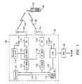
- FIGURE 1 is a schematic block diagram of a radio BS that can be used to perform measurements for determining the TOA of signals, in accordance with a preferred embodiment of the present invention.
- the BS 100 can be connected for communication with a wire-bound network (not explicitly shown) via a mobile services switching center (MSC) 125.
- MSC mobile services switching center
- the BS 100 performs TOA measurements for a mobile radio terminal (MS) 130 over a radio connection, of which the two uplink paths 101, 102 are shown that provide diversity.
- MS mobile radio terminal
- each antenna 103 and 104 Associated with each antenna 103 and 104 is a respective receiver 111a and 111b, radio frequency (RF) demodulator 112a and 112b, and intermediate frequency (IF) demodulator 113a and 113b.
- a received frequency synthesizer 114 is connected to each of the RF demodulators 112a and 112b and control unit 115. The received frequency synthesizer 114 enables reception of particular radio channels using these connections.
- Demodulated signals from the IF demodulators 113a and 113b are coupled to an equalizer 135 over respective connections 116 and 117.
- the equalizer is also connected to other components in the BS 100.
- the demodulated signals from the IF demodulators 113a and 113b are also coupled to a modified-RX (ModRX) 118.
- the ModRX 118 functions to measure the TOA of the signals received from the MS 130, and reports the results of these measurements to the MSC 125 via a connection to the control unit 115.
- the processing of the TOA measurements is performed by the processor 119 in the ModRX 118.
- the processing of the TOA measurements can be performed by a processor in control unit 115, or in the wire-bound network (e.g., in the MSC 125).
- the equalizer 135 combines the two demodulated signals on connections 116 and 117, in order to take advantage of both the incoming line-of-sight and reflected radio energy.
- the ModRX 118 processes these two demodulated signals separately, because signal fading is a desired effect when measuring TOA. In other words, the fading eliminates reflected beams for some received bursts, and thus provides only the desired line-of-sight signals.
- FIGUREs 2A-2E illustrate a series of wave-forms associated with a method for determining a sample TOA(i), which can be implemented in accordance with the preferred embodiment of the present invention.
- the wave-forms shown in FIGURE 2A represent one burst of the received signal on connection 116 (or 117), which contains variable data 1 and data 2, as well as a training sequence (known in advance) in the middle of the burst.
- the solid wave-form represents a direct (line-of-sight) received signal
- the dotted wave-form represents a received reflection of the burst (thus slightly delayed in time).
- FIGURE 2B illustrate the theoretical responses of a correlation between the incoming direct and reflected bursts of the signal on connection 116 (or 117), and the known training sequence available in the ModRX 118 for determining TOA.
- the combined correlation response (“Channel Impulse Response” or CIR) of these bursts as processed in the ModRX 118, is shown in FIGURE 2C .
- the suffix "i" indicates a particular received burst.
- the CIRi wave-form shown in FIGURE 2C is a complex value comprising amplitude and phase.
- the central part of the CIRi is given by a limited number of samples (e.g., 5), but a complete signal as shown in FIGURE 2C is reconstructed by the processor 119 using a conventional interpolation technique.
- the wave-form shown in FIGURE 2D illustrates the squared absolute value of the CIRi, which is referred to as the "estimated channel power profile" or CPPi.
- the integrated signal ICPP(Ni) has a higher peak value, h, for the desired signal, and a bias value, b, for the undesired noise, but with a spread sigma for the noise that is not amplified to the same extent by the integration.
- the bias value, b is eliminated during processing, and the quality "Q" of the ICPP(Ni) is defined as h/sigma.
- a suffix, Ni, assigned to the Integrated Channel Power Profile ICPP(Ni) indicates that a certain selection "i" of N bursts has been integrated.
- a TOA(i) value is associated with the ICPP(Ni) and is entered as one of 100 points, for example, in the diagram shown in FIGURE 3 .
- FIGURE 3 is a diagram that can be used to derive the estimated minimum time of arrival (TOAe) based on 70 bursts, in accordance with an exemplary embodiment of the present invention.
- FIGURE 3 discloses a diagram that can be used to plot TOA(i) versus frequency of occurrence, it is shown as a diagram for illustrative purposes only and is not intended to so limit the present invention.
- the diagram of FIGURE 3 can be implemented, for example, as a multi-dimensional matrix or array, with the rows (or columns) including each TOA(i), and the columns (or rows) including each occurrence.
- An alternative representation is given in FIGURE 5 . which shows a cumulative distribution curve for the same 70 bursts.
- the present invention preferably uses M (e.g., 70) received bursts containing at least a part that has identical known contents of bits in all received bursts (e.g., a training sequence).
- M e.g., 70
- received bursts containing at least a part that has identical known contents of bits in all received bursts (e.g., a training sequence).
- a different embodiment can use (e.g., 70) received bursts containing different (non-identical) information, but information still known to the receiver, which enables the processor to produce CIRi by correlating each burst with its known contents.
- the noise is reduced to a preselected level by "adding" (e.g., incoherent integration of the CPPi) a required number of N bursts which are randomly selected from among the M received bursts, and determining the TOA(i) for this sum, ICPP(Ni), of N bursts.
- This first procedure is repeated a plurality (e.g., 100) times, which for this example, results in 100 values of TOA(i) which are entered into the diagram show in FIGURE 3 .
- the primary advantage of this first procedure is that the random selections, Ni, will sometimes comprise bursts that contain mostly (or only) bursts received on the shortest path (line-of-sight path).
- the minimum TOAe is read in the diagram shown in FIGURE 3 .
- the shortest values of TOA(i) are excluded because they may be due to noise and multipath effects displacing peaks.
- Empirical information shows that a suitable reading for TOAe is where 5% of the occurring TOA(i) are earlier than the TOAe, and 95% of the occurring TOA(i) are later than the TOAe.
- FIGURE 4 is a flow diagram that illustrates an exemplary method 400 that can be used to implement the present invention.
- M bursts of the received signal at connection 116 (or 117) that contain a known bit sequence are measured by ModRX 118.
- these bursts can be access bursts sent on the uplink from the MS 130 as a response to an intra-cell handover order, or a handover order back to the pertinent (old) traffic channel, with the order coming from a serving BS (e.g., 100) in a GSM network.
- a serving BS e.g., 100
- the received channel impulse responses, CIRi (as shown in FIGURE 2C ), which are each associated with one particular burst and contain complex information, are each processed to form an estimated channel power profile, CPPi (as shown in FIGURE 2D ) equal to the squared absolute value of the CIRi. Consequently, there will be M values of CPPi.
- a check is made to determine whether the noise has been reduced enough for the derived ICPP(Ni) to have a minimum quality defined by the ratio h/sigma (compare FIGURE 2E ). If the h/sigma ratio is less than a predetermined threshold, the derived ICPP(Ni) has to be improved by repeating the steps 403-405 using one additional CPPi randomly selected from among the not yet selected CPPi.
- the minimum quality has been reached, and the resulting TOA(i) (as shown in FIGURE 2E ) is entered into the diagram shown in FIGURE 3 . The flow then continues to step 408.
- step 408 the question is answered about whether or not the predetermined number of TOAi values has been reached. If not, the steps 403-407 are repeated as described above, until the required predetermined number of TOAi values has been reached.
- the lowest TOA(i) in the diagram of FIGURE 3 is selected, because this value of TOA represents the TOA of the burst as received on the shortest path (line-of-sight path).
- the selection is performed according to the description for FIGURE 3 or 5 above, thereby rejecting the influence of noise.
- TDOA is measured instead of TOA.
- the procedure is the same as the procedure described above for TOA, except that time measurements are made relative to another signal rather than relative to a time reference. If TDOA measurements are performed, the cross-correlation of two received signals can be performed. As such, the TDOA estimate can be the highest peak of the cross-correlation output.
- the above-described inventive incoherent integration approach can also be used.
- two base stations should be involved, in order to have two signals to perform the TDOA measurement.
- the cross-correlation output can be substituted for the CIR
- the cross-correlation power profile can be substituted for the CPP (where the CPP represents the squared absolute value of the cross-correlation output).
- a spatial signature can be estimated from, for example, the received signal from a directional-or narrow-beam antenna (e.g., an adaptive antenna or fixed lobe antenna.
- the DOA estimate can be the highest peak of the estimated spatial signature.
- the spatial signature can be substituted for the CIR
- the spatial signal power profile can be substituted for the CPP (where the CPP represents the squared absolute value of the spatial signature).
- the line-of-sight (LOS) signal component corresponds to the "center of gravity" of the ICPP (i.e., the LOS component does not correspond to the lower part of the correlation output, such as in the TOA measurement case). Consequently, there would be little or no advantage in performing incoherent integration with less than the total number, M, of the received bursts. Therefore, in these cases, all bursts are used in the incoherent integration process, and the TDOA and DOA estimates are the "center of gravity" of the ICPP.
- an antenna array is used in a BS for measuring beams from different directions separately. Subsequently, the line-of-sight beam is selected for the TOA measurements (shortest TOAi).
- the occurrences of TOA(i) are weighted by their quality (i.e., by their h/sigma value), which is an indication of the noise involved. Consequently, remote BSs receiving weak signals are given less influence over a position determination process.
- FIGURE 6 is a flow diagram that illustrates a first auxiliary method, for rejecting interference in accordance with the present invention.
- This method teaches how to overcome disturbances from other mobile terminals (e.g., whose position is not being determined). For example, in the GSM, there are eight different training sequences used which have a certain correlation to each other, and can cause disturbances to the measurements performed for a mobile terminal whose position is being determined.
- the channel impulse responses, CIRj are estimated for all possible interferer training sequences on all M received bursts.
- the corresponding channel power profiles, CPPj are formed, by taking the squared absolute value of the CIRj.
- the average carrier-to-interference ratio, C/I is estimated for each such interferer training sequence, while treating the "C" part as the power of the interferer of interest and the "I” part as the power of other signals.
- a determination is made about whether the disturbance is to be rejected (i.e., subtracted) from the received bursts, which is the case if the C/I exceeds a first threshold value, T1.
- those training sequences that meet the condition of step 604 are convoluted (symbolized by a "*") with the CIRj, and subtracted from the received bursts.
- FIGURE 7 is a flow diagram that illustrates a second auxiliary method, for detecting the measurement region in the time domain, in accordance with the present invention.
- this method is particularly useful in cases of high noise compared to the signal of interest.
- This second auxiliary method comprises incoherently integrating all M bursts received, which results in a relatively wide pulse that emerges from the noise, and indicates the approximate time when the training sequence of the measured mobile terminal (whose position is being determined) is to be found.
- the channel power profiles, CPPi, of the received carrier are formed for all M bursts.
- the incoherent integration of all the CPPi is performed, and the highest peak corresponds to the location of the training sequence.
- the C/I is estimated, while treating the "C” part as the power of the carrier, and the "I” part as the power of other signals.
- a determination is made about whether the result from steps 701-702 is acceptable (C/I>T2), or the noise is strong enough such that additional steps have to be taken for an acceptable result. If, at step 704, the value of C/I is above the threshold T2. the result from steps 701-702 is accepted.
- the bursts with high influence from noise are weighted down as follows.
- the bursts with high energy contents are discriminated by assigning them a low weight factor, Wi', and the bursts with low energy contents are assigned a high weight factor for Wi'.
- the highest peak of this sum corresponds to the location of the training sequence.
- the principle of assigning weights to the received bursts depending on the C/I can also be applied to the processing of measured bursts in order to determine a time of arrival, TOAe.
- the training sequence can be used to estimate the power of the signal as represented by FIGURE 2D , and the power of the signal plus noise as represented by FIGURE 2A .
- weights W" can be assigned to each CPPi (i.e., W" CPPi in FIGURE 2D ), based on these estimated signal power and signal plus noise power, before forming the integrated signal, ICPP(Ni), and the square root of this signal, as depicted in FIGURE 2E .
Abstract
Description
- The present invention relates in general to the mobile radio communications field and, in particular, to a method and system for use in determining the geographical position of a mobile radio terminal.
- Commonly-assigned
U.S. Patent Application US 5,592,969 to Hagerman et al ., describes a method for determining the position of a mobile radio terminal (hereinafter mobile station or MS), which makes use of uplink Time of Arrival (TOA) and Direction of Arrival (DOA) measurements. Slight mention is made in that disclosure about repeating the same uplink signal a number of times, in order to improve the accuracy of the TOA determinations. However, the disclosure does not provide any details about how this improvement can be achieved. - Commonly-assigned
U.S. Patent US 6,064,888 , which has been filed on the same day as the present application, discloses a method and apparatus for providing a "prime" uplink signal from a MS whose position is to be determined. The present invention is related by subject matter to the above-described Patent Applications and teaches how to process a repeated uplink signal, such as, for example, the "prime" uplink signal from a MS whose position is to be determined. - International patent application
WO97/11384 - US patent
US 5,534,876 describes a multilateration location system includes a locatable unit and any number of known-position locators. A time of arrival detector determines instants in time when a location signal transmitted by the locatable unit arrives at various known-position locators.
For each combination of two known-position locators that receive the location signal, a pre-estimation process determines whether the difference in arrival times is less than or equal to a maximum propagation duration for the locator pair. The maximum propagation duration is based upon the distance between the locators in the locator pair. If the difference is greater than the maximum propagation duration, the difference is omitted from the data set processed by a multilateration calculation process. A post estimation filtering process screens out location estimates that are too distant from a predicted position. - US patent
US 5,327,144 describes a cellular telephone location system for automatically recording the location of one or more mobile cellular telephones comprises three or more cell site systems. Each cell site system is located at a cell site of a cellular telephone system. Each cell site system includes an antenna that may be mounted on the same tower or building as the antenna employed by the cellular telephone system and equipment that may be housed in the equipment enclosure of the corresponding cell site. The cell site systems are coupled via T1 communication links to a central site. The central site may be collocated with the cellular telephone system's MTSO. The central site is further coupled to a database, which may be remotely located from the central site and made available to subscribers. - US patent
US 5,526,357 describes a multilaterating two-way message delivery system for mobile resource management provides efficient two-way radio data communication for multitudes of portable transponders using a single frequency in half-duplex communication. The system includes at least one transponder device which transmits and receives data using a radio frequency communication link, and an array of at least three base stations which communicate with the transponder device using the radio frequency communication link. The radio frequency communication link employed by each base station and the transponder device is designed to provide muitilateration information and to deliver message data simultaneously. Further, a control arrangement is coupled to the array of base stations to coordinate the communication between the base stations and the transponder devices. Time-division multiplex and spread spectrum technology is employed by the system for communication efficiency and minimizing the effect of multipath interference. - European patent application
EP 0 318 685 describes a method and apparatus for phase-coherently demodulating a multipath-impaired time division multiple access QPSK data timeslot is disclosed. A quadrature separator generates multipath-impaired intermediate signals which, during a predetermined synchronizing sequence for the timeslot, are applied to a pair of synchronizing correlators to generate quadrature multipath profiles. These profiles then are used to modify subsequently received QPSK timeslot signals at the separator outputs to coherently construct multipath compensated I and Q channel data. - The CME 20 System, which is a Global System for Mobile Communications (GSM) implementation manufactured by Telefonaktiebolaget LM Ericsson, sends uplink messages with a Timing Advance (TA) to compensate for the radio signal propagation delay caused by the distance between the radio base station (BS) and the MS. The TA value is determined by a procedure of selecting the smallest TA value from a number of measurements made by the BS on several access bursts that have been transmitted by the MS. For TA value determinations, this procedure solves the radio signal multipath propagation problem (i.e., when the signal propagates along a line of sight path and also along one or more reflected paths). This procedure is hereinafter referred to as the "minimum time" method.
- According to the present invention, there is provided a method for determining, in a radio environment with time dispersion, the distance between a radio transmitter and a radio receiver according to appended
independent claim 1, a method for performing, in a radio environment with time dispersion and noise, a determination of an earliest time-of-arrival for a known received signal transmitted repetitively as M samples from a remote transmitter, said M samples subject to fading such that a time-of-arrival varies between at least two of said M samples according to appended independent claim 12, and a system for use in determining the distance between a mobile station and a base station in a mobile network according to appended independent claim 17. Preferred embodiments are defined in the appended dependent claims. - For a better understanding of the invention and to show how the same may be carried into effect, reference will now be made, by way of example, to the accompanying drawings, in which:
-
FIGURE 1 is a schematic block diagram of a radio BS that can be used to perform measurements for determining TOA, in accordance with a preferred embodiment of the present invention; -
FIGUREs 2A-2E illustrate a series of wave-forms associated with a method for determining a sample TOA(i), which can be implemented in accordance with the preferred embodiment of the present invention; -
FIGURE 3 is a diagram that can be used to derive an estimated minimum Time of Arrival or TOAe based on seventy bursts from a TX, in accordance with an exemplary embodiment of the present invention; -
FIGURE 4 is a flow diagram that can be used to implement an exemplary embodiment of the present invention; -
FIGURE 5 is a diagram of an alternative representation for the diagram ofFIGURE 3 , and which shows a cumulative distribution curve for the same bursts; -
FIGURE 6 is a flow diagram that illustrates a first auxiliary method, for rejecting interference in accordance with the present invention; and -
FIGURE 7 is a flow diagram that illustrates a second auxiliary method, for detecting the measurement region in the time domain, in accordance with the present invention. - A problem addressed by an embodiment of the present invention is how to process a number of identical digital signals transmitted from a radio transmitter(TX), which are subject to noise and multipath propagation when received in a radio receiver (RX), in order to more accurately determine the distance between the TX and RX than what is possible using the above-described "minimum time" method.
- Another problem addressed by an embodiment of the present invention is how to process the above-described digital signals if the signal parameter being determined in the RX is the TOA.
- Still another problem addressed by an embodiment of the present invention is how to process the above-described digital signals if the signal parameter being determined in the RX is the TOA, and there are TOA and DOA measurements being made in a BS.
- It is, therefore, an object of an embodiment of the present invention to provide a method and apparatus to more accurately determine the distance between an RX and TX, by processing radio signals that have been subject to noise and multipath propagation, wherein the radio signals are being transmitted repeatedly from the same TX and received in anRX.
- It is another object of an embodiment of the present invention to provide a method and apparatus in accordance with the above-described object, whereby the signal parameter being processed is TOA.
- It is yet another object of an embodiment of the present invention to provide a method and apparatus in accordance with the above-described objects, whereby the signal parameters being processed are TOA, TDOA and DOA.
- The foregoing and other objects are achieved by a method and apparatus for improving time measurement accuracy, which includes transmitting "M" samples of the same signal from a TX, receiving the "M" signal samples along with multipath components and noise, for each of the received "M" samples, determining in the RX an estimated channel power profile (CPPi), selecting "N" out of the "M" received samples, performing incoherent integration of the CPPi for the "N" samples, which results in an integrated signal, ICPP (Ni), determining if the signal-to-noise quality of the ICPP(Ni) is greater than or equal to a predetermined threshold value, and if not, improving the signal-to-noise quality of ICPP(Ni) as required, by redoing the incoherent integration with successively one additional received sample CPPi until the signal-to-noise quality of the ICPP(Ni) is greater than or equal to the predetermined threshold value, determining the TOA (i), including the case of determining TOA(i) from the maximum signal amplitude, and entering that TOA(i) value into a diagram that shows a frequency of occurrence as a function of TOA (i), repeating the whole procedure "X" times by selecting a new combination of "N" out of "M" samples, which results in "X" additional points in the frequency of occurrence diagram, and reading the minimum value TOA (min) as the time value having "z" of all occurrences with higher TOA(i) values 0.7.
- An important technical advantage of an embodiment of the present invention is that the method for improving the quality of the signals, which requires the addition of many signals (incoherent integration), is performed in such a way that also allows the minimum TOA to be determined as in the "minimum time" approach described above.
- Another important technical advantage of an embodiment of the present invention is that the elimination of noise thus provided allows more remote BSs to take part in determining the position of a MS, which not only improves the accuracy of each measurement made, but also improves the accuracy overall because of the increased number of BSs that can participate in the position determination process.
- The preferred embodiment of the present invention and its advantages are best understood by referring to
FIGUREs 1-7 of the drawings, like numerals being used for like and corresponding parts of the various drawings. - Essentially, the present invention provides a method for making time measurements which can be used in determining the geographical position of a mobile radio terminal. As such, the time measurements involved can be TOA measurements or Time Difference of Arrival (TDOA) measurements. The following description discloses an embodiment of the invention wherein TOA measurements are preferably used.
- Specifically,
FIGURE 1 is a schematic block diagram of a radio BS that can be used to perform measurements for determining the TOA of signals, in accordance with a preferred embodiment of the present invention. As shown, theBS 100 can be connected for communication with a wire-bound network (not explicitly shown) via a mobile services switching center (MSC) 125. As shown, theBS 100 performs TOA measurements for a mobile radio terminal (MS) 130 over a radio connection, of which the twouplink paths antenna respective receiver 111a and 111b, radio frequency (RF)demodulator 112a and 112b, and intermediate frequency (IF)demodulator 113a and 113b. A receivedfrequency synthesizer 114 is connected to each of theRF demodulators 112a and 112b andcontrol unit 115. The receivedfrequency synthesizer 114 enables reception of particular radio channels using these connections. Demodulated signals from theIF demodulators 113a and 113b are coupled to anequalizer 135 overrespective connections 116 and 117. Although not explicitly shown, the equalizer is also connected to other components in theBS 100. - The demodulated signals from the IF demodulators 113a and 113b are also coupled to a modified-RX (ModRX) 118. The
ModRX 118, the function and operation of which are described in the above-mentionedU.S. Patent Application Serial No. 08/894,466 to Hagerman et al ., functions to measure the TOA of the signals received from theMS 130, and reports the results of these measurements to theMSC 125 via a connection to thecontrol unit 115. Preferably, the processing of the TOA measurements is performed by theprocessor 119 in theModRX 118. Alternatively, the processing of the TOA measurements can be performed by a processor incontrol unit 115, or in the wire-bound network (e.g., in the MSC 125). Theequalizer 135 combines the two demodulated signals onconnections 116 and 117, in order to take advantage of both the incoming line-of-sight and reflected radio energy. On the other hand, theModRX 118 processes these two demodulated signals separately, because signal fading is a desired effect when measuring TOA. In other words, the fading eliminates reflected beams for some received bursts, and thus provides only the desired line-of-sight signals. -
FIGUREs 2A-2E illustrate a series of wave-forms associated with a method for determining a sample TOA(i), which can be implemented in accordance with the preferred embodiment of the present invention. The wave-forms shown inFIGURE 2A represent one burst of the received signal on connection 116 (or 117), which containsvariable data 1 anddata 2, as well as a training sequence (known in advance) in the middle of the burst. The solid wave-form represents a direct (line-of-sight) received signal, and the dotted wave-form represents a received reflection of the burst (thus slightly delayed in time). - The wave-forms shown in
FIGURE 2B illustrate the theoretical responses of a correlation between the incoming direct and reflected bursts of the signal on connection 116 (or 117), and the known training sequence available in theModRX 118 for determining TOA. The combined correlation response ("Channel Impulse Response" or CIR) of these bursts as processed in theModRX 118, is shown inFIGURE 2C . The suffix "i" indicates a particular received burst. - The CIRi wave-form shown in
FIGURE 2C is a complex value comprising amplitude and phase. The central part of the CIRi is given by a limited number of samples (e.g., 5), but a complete signal as shown inFIGURE 2C is reconstructed by theprocessor 119 using a conventional interpolation technique. The wave-form shown inFIGURE 2D illustrates the squared absolute value of the CIRi, which is referred to as the "estimated channel power profile" or CPPi. The wave-form depicted for the CPPi is optimistic, and in actual cases often contains a large noise component. Consequently, N out of M (e.g., M=70) CPPi are integrated into a signal ICPP(Ni), as shown inFIGURE 2E . - The integrated signal ICPP(Ni) has a higher peak value, h, for the desired signal, and a bias value, b, for the undesired noise, but with a spread sigma for the noise that is not amplified to the same extent by the integration. The bias value, b, is eliminated during processing, and the quality "Q" of the ICPP(Ni) is defined as h/sigma. A suffix, Ni, assigned to the Integrated Channel Power Profile ICPP(Ni) indicates that a certain selection "i" of N bursts has been integrated. A TOA(i) value is associated with the ICPP(Ni) and is entered as one of 100 points, for example, in the diagram shown in
FIGURE 3 . -
FIGURE 3 is a diagram that can be used to derive the estimated minimum time of arrival (TOAe) based on 70 bursts, in accordance with an exemplary embodiment of the present invention. AlthoughFIGURE 3 discloses a diagram that can be used to plot TOA(i) versus frequency of occurrence, it is shown as a diagram for illustrative purposes only and is not intended to so limit the present invention. In an automated processing environment, the diagram ofFIGURE 3 can be implemented, for example, as a multi-dimensional matrix or array, with the rows (or columns) including each TOA(i), and the columns (or rows) including each occurrence. An alternative representation is given inFIGURE 5 . which shows a cumulative distribution curve for the same 70 bursts. - The present invention preferably uses M (e.g., 70) received bursts containing at least a part that has identical known contents of bits in all received bursts (e.g., a training sequence). However, note that a different embodiment can use (e.g., 70) received bursts containing different (non-identical) information, but information still known to the receiver, which enables the processor to produce CIRi by correlating each burst with its known contents.
- Using a first procedure, the noise is reduced to a preselected level by "adding" (e.g., incoherent integration of the CPPi) a required number of N bursts which are randomly selected from among the M received bursts, and determining the TOA(i) for this sum, ICPP(Ni), of N bursts. This first procedure is repeated a plurality (e.g., 100) times, which for this example, results in 100 values of TOA(i) which are entered into the diagram show in
FIGURE 3 . The primary advantage of this first procedure is that the random selections, Ni, will sometimes comprise bursts that contain mostly (or only) bursts received on the shortest path (line-of-sight path). Using a second procedure, the minimum TOAe is read in the diagram shown inFIGURE 3 . However, the shortest values of TOA(i) are excluded because they may be due to noise and multipath effects displacing peaks. Empirical information shows that a suitable reading for TOAe is where 5% of the occurring TOA(i) are earlier than the TOAe, and 95% of the occurring TOA(i) are later than the TOAe. -
FIGURE 4 is a flow diagram that illustrates anexemplary method 400 that can be used to implement the present invention. Atstep 401, M bursts of the received signal at connection 116 (or 117) that contain a known bit sequence are measured byModRX 118. For example, these bursts can be access bursts sent on the uplink from theMS 130 as a response to an intra-cell handover order, or a handover order back to the pertinent (old) traffic channel, with the order coming from a serving BS (e.g., 100) in a GSM network. If these access bursts are not answered by theBS 100, up to 70 bursts will be transmitted by theMS 130 before a time-out occurs and places the MS back on the previously used (old) traffic channel. The demodulated signals onconnections 116 and 117 both include the received access bursts, or together 2 x 70 = 140 bursts maximum, each of which can be treated as an independent burst with respect to the method of the present invention. - At
step 402, the received channel impulse responses, CIRi (as shown inFIGURE 2C ), which are each associated with one particular burst and contain complex information, are each processed to form an estimated channel power profile, CPPi (as shown inFIGURE 2D ) equal to the squared absolute value of the CIRi. Consequently, there will be M values of CPPi. Atstep 403, theprocessor 119 randomly selects N out of the M values (wave-forms) of the CPPi starting with N=10, for example. - At
step 404, an incoherent integration of the N=10 selected wave-forms CPPi results in one integrated channel power profile ICPP(Ni), as shown inFIGURE 2E . Atstep 405, a check is made to determine whether the noise has been reduced enough for the derived ICPP(Ni) to have a minimum quality defined by the ratio h/sigma (compareFIGURE 2E ). If the h/sigma ratio is less than a predetermined threshold, the derived ICPP(Ni) has to be improved by repeating the steps 403-405 using one additional CPPi randomly selected from among the not yet selected CPPi. Atstep 407, the minimum quality has been reached, and the resulting TOA(i) (as shown inFIGURE 2E ) is entered into the diagram shown inFIGURE 3 . The flow then continues to step 408. - At
step 408, the question is answered about whether or not the predetermined number of TOAi values has been reached. If not, the steps 403-407 are repeated as described above, until the required predetermined number of TOAi values has been reached. - If so, at
step 409, the lowest TOA(i) in the diagram ofFIGURE 3 is selected, because this value of TOA represents the TOA of the burst as received on the shortest path (line-of-sight path). However, the selection is performed according to the description forFIGURE 3 or 5 above, thereby rejecting the influence of noise. - In another embodiment of the present invention, TDOA is measured instead of TOA. For the TDOA measurements, the procedure is the same as the procedure described above for TOA, except that time measurements are made relative to another signal rather than relative to a time reference. If TDOA measurements are performed, the cross-correlation of two received signals can be performed. As such, the TDOA estimate can be the highest peak of the cross-correlation output.
- Also, if TDOA measurements are performed, the above-described inventive incoherent integration approach can also be used. However, two base stations should be involved, in order to have two signals to perform the TDOA measurement. As such, the cross-correlation output can be substituted for the CIR, and the cross-correlation power profile can be substituted for the CPP (where the CPP represents the squared absolute value of the cross-correlation output).
- In another embodiment, if DOA measurements are performed, a spatial signature can be estimated from, for example, the received signal from a directional-or narrow-beam antenna (e.g., an adaptive antenna or fixed lobe antenna. As such, the DOA estimate can be the highest peak of the estimated spatial signature.
- The above-described inventive incoherent integration approach can also be used if DOA measurements are performed. As such, the spatial signature can be substituted for the CIR, and the spatial signal power profile can be substituted for the CPP (where the CPP represents the squared absolute value of the spatial signature).
- In both the TDOA and DOA measurement cases, the line-of-sight (LOS) signal component corresponds to the "center of gravity" of the ICPP (i.e., the LOS component does not correspond to the lower part of the correlation output, such as in the TOA measurement case). Consequently, there would be little or no advantage in performing incoherent integration with less than the total number, M, of the received bursts. Therefore, in these cases, all bursts are used in the incoherent integration process, and the TDOA and DOA estimates are the "center of gravity" of the ICPP.
- In yet another embodiment of the present invention, an antenna array is used in a BS for measuring beams from different directions separately. Subsequently, the line-of-sight beam is selected for the TOA measurements (shortest TOAi).
- In still another embodiment of the present invention, the occurrences of TOA(i) are weighted by their quality (i.e., by their h/sigma value), which is an indication of the noise involved. Consequently, remote BSs receiving weak signals are given less influence over a position determination process.
-
FIGURE 6 is a flow diagram that illustrates a first auxiliary method, for rejecting interference in accordance with the present invention. This method teaches how to overcome disturbances from other mobile terminals (e.g., whose position is not being determined). For example, in the GSM, there are eight different training sequences used which have a certain correlation to each other, and can cause disturbances to the measurements performed for a mobile terminal whose position is being determined. - At
step 601 of the method, the channel impulse responses, CIRj, are estimated for all possible interferer training sequences on all M received bursts. Atstep 602, the corresponding channel power profiles, CPPj, are formed, by taking the squared absolute value of the CIRj. Atstep 603, the average carrier-to-interference ratio, C/I, is estimated for each such interferer training sequence, while treating the "C" part as the power of the interferer of interest and the "I" part as the power of other signals. Atstep 604, a determination is made about whether the disturbance is to be rejected (i.e., subtracted) from the received bursts, which is the case if the C/I exceeds a first threshold value, T1. Atstep 605, those training sequences that meet the condition ofstep 604 are convoluted (symbolized by a "*") with the CIRj, and subtracted from the received bursts. -
FIGURE 7 is a flow diagram that illustrates a second auxiliary method, for detecting the measurement region in the time domain, in accordance with the present invention. For example, this method is particularly useful in cases of high noise compared to the signal of interest. As such, before searching for correlation peaks (as shown and described above with respect toFIGURE 2B ), there can be a problem with determining the approximate time when the training sequences are found among the noise. This second auxiliary method comprises incoherently integrating all M bursts received, which results in a relatively wide pulse that emerges from the noise, and indicates the approximate time when the training sequence of the measured mobile terminal (whose position is being determined) is to be found. - At
step 701 of the method, the channel power profiles, CPPi, of the received carrier are formed for all M bursts. Atstep 702, the incoherent integration of all the CPPi is performed, and the highest peak corresponds to the location of the training sequence. Atstep 703, the C/I is estimated, while treating the "C" part as the power of the carrier, and the "I" part as the power of other signals. Atstep 704, a determination is made about whether the result from steps 701-702 is acceptable (C/I>T2), or the noise is strong enough such that additional steps have to be taken for an acceptable result. If, atstep 704, the value of C/I is above the threshold T2. the result from steps 701-702 is accepted. Otherwise, the bursts with high influence from noise are weighted down as follows. Atstep 705, the bursts with high energy contents (which are likely due to noise) are discriminated by assigning them a low weight factor, Wi', and the bursts with low energy contents are assigned a high weight factor for Wi'. Atstep 706, a sum of all M weighted bursts is formed in accordance with the formula:
- The highest peak of this sum corresponds to the location of the training sequence.
- The principle of assigning weights to the received bursts depending on the C/I can also be applied to the processing of measured bursts in order to determine a time of arrival, TOAe. The training sequence can be used to estimate the power of the signal as represented by
FIGURE 2D , and the power of the signal plus noise as represented byFIGURE 2A . Then, weights W" can be assigned to each CPPi (i.e., W" CPPi inFIGURE 2D ), based on these estimated signal power and signal plus noise power, before forming the integrated signal, ICPP(Ni), and the square root of this signal, as depicted inFIGURE 2E . - Although a preferred embodiment of the method and apparatus of the present invention has been illustrated in the accompanying Drawings and described in the foregoing Detailed Description, it will be understood that the invention is not limited to the embodiment disclosed, but is capable of numerous rearrangements, modifications and substitutions without departing from the invention as set forth and defined by the following claims. In particular, the methods described and claimed herein for uplink applications can be used alternatively for downlink applications.
Claims (17)
- A method for determining, in a radio environment with time dispersion, the distance between a radio transmitter (MS; 130) and a radio receiver (BS;100), comprising the steps of:transmitting from said radio transmitter M samples (101;102) of a signal;receiving in said receiver said M samples together with multipath components and noise;determining an estimated channel power profile, CPPi, for each of said M samples;selecting a first set of N samples from said M samples;performing integration for said estimated channel power profiles for said first set of N samples to form a first integrated signal, ICCP (Ni);if a quality level of said first integrated signal with respect to signal to noise is less than a predetermined threshold, and until a quality level of said first integrated signal with respect to signal to noise is greater than or equal to said predetermined threshold, repeating:selecting another sample from said M samples; andperforming integration for said estimated channel power profiles for said first set of N samples and each said another sample to form a second integrated signal as said first integrated signal;determining a time-of-arrival, TOAi, of a maximum level of said first integrated signal having a quality level with respect to signal to noise that is greater than or equal to said predetermined threshold;entering said time-of-arrival into a time-of-arrival versus frequency of occurrence array;repeating all of said selecting through said entering steps a predetermined number of times; anddetermining a minimum value estimated time-of-arrival from said array.
- The method of Claim 1, wherein the step of determining a minimum value estimated time-of-arrival from said array comprises reading out from said array a time value having a first predetermined number of all occurrences being higher time-of-arrival values and a second predetermined number, which is a complement of said first predetermined number, of all occurrences being lower time-of-arrival values.
- The method of Claim 2, wherein said first predetermined number is greater than 70%, and said second predetermined number is 100% minus said first predetermined number in percent.
- The method of Claim 1, wherein the receiving step comprises receiving said M samples separately in two independent radio receivers (103;104) to form two times said M samples.
- The method of Claim 1, wherein said array comprises a matrix.
- The method of Claim 1, wherein a manual version of said entering step comprises entering said time-of-arrival into a time-of-arrival versus frequency of occurrence diagram.
- The method of Claim 1, wherein:the radio transmitter and radio receiver are a mobile station (MS; 130) and a base station (BS; 100) in a mobile network, respectively;at least one other sample is selected with said another sample; andsaid performing integration for said estimated channel power profiles, CPPi, for said first set of N samples and said another sample performs integration for said estimated channel power profiles for said first set of N samples, said another sample and said at least one other sample.
- The method of Claim 7, wherein said performing integration steps comprise incoherent integration.
- The method of Claim 7, wherein said minimum value estimated time-of-arrival represents a shortest distance between said mobile station and said base station.
- The method of Claim 7, wherein the step of determining a minimum value estimated time-of-arrival comprises reading out from said array a time value having a first number of all occurrences being higher time-of-arrival values, and a complement of said first number of all occurrences being lower time-of-arrival values.
- The method of Claim 10, wherein said first number is greater than 0.7, and said complement of said first number is 1 minus said first number.
- A method for performing, in a radio environment with time dispersion and noise, a determination of an earliest time-of-arrival for a known received signal transmitted repetitively as M samples from a remote transmitter, said M samples subject to fading such that a time-of-arrival varies between at least two of said M samples, comprising the steps of :selecting from among said M samples a first set of samples;forming a mathematical function from said first set of samples to improve a signal-to-noise quality without destroying time-of-arrival information;repeating said selecting and forming steps for additional sets of samples in addition to said first set of samples;determining a time-of-arrival for each of said first set and said additional sets of samples; andstatistically processing each said time-of-arrival obtained from said determining step to obtain an estimate of said earliest time-of-arrival.
- The method of Claim 12, wherein said first set of samples and said additional sets of samples comprise an equal number of N samples.
- The method of Claim 12, wherein said first set of samples and said additional sets of samples comprise different numbers of samples.
- The method of Claim 12, wherein a number of samples used in said first set of samples and said additional sets of samples is selected to obtain a desired signal-to-noise quality for each of said first set of samples and said additional sets of samples.
- The method of Claim 12, wherein a number of samples used in said first set of samples and said additional sets of samples is selected to obtain a desired signal-to-noise quality defined by h/sigma.
- A system for use in determining the distance between a mobile station (MS; 130) and a base station (BS;100) in a mobile network, comprising:a mobile transmitter (130) arranged to transmit a first plurality of signal samples;a base station receiver (100) arranged to receive said first plurality of signal samples; anda processor (119) coupled to said base station receiver, said processor being arranged to:form an estimated channel power profile value, CPPi, for each of said first plurality of signal samples;select a second plurality of samples from said estimated channel power profile values;integrate said estimated channel power profile values for said second plurality of samples to form a first integrated channel power profile, ICCP(Ni);if a quality level of said first integrated channel power profile is less than a predetermined threshold value, and until a quality level of said first integrated channel power profile is greater than or equal to said predetermined threshold value, repeat:select at least one additional sample from said estimated channel power profile values; andintegrate said estimated channel power profiles for said second plurality of samples and each said at least one additional sample to form a second integrated channel power profile as said first integrated channel power profile;determine a time-of-arrival, TOAi, for a maximum signal amplitude of said first integrated channel power profile having a quality level greater than or equal to said predetermined threshold value; andenter said time-of-arrival into a time-of-arrival versus frequency of occurrence array;repeat the select a second plurality of samples operation through the enter operation a predetermined number of times; anddetermine a minimum time-of-arrival from said array.
Applications Claiming Priority (3)
| Application Number | Priority Date | Filing Date | Title |
|---|---|---|---|
| US978960 | 1997-11-26 | ||
| US08/978,960 US6009334A (en) | 1997-11-26 | 1997-11-26 | Method and system for determining position of mobile radio terminals |
| PCT/SE1998/002112 WO1999027738A1 (en) | 1997-11-26 | 1998-11-20 | Method and system for determining position of mobile radio terminals |
Publications (2)
| Publication Number | Publication Date |
|---|---|
| EP1034677A1 EP1034677A1 (en) | 2000-09-13 |
| EP1034677B1 true EP1034677B1 (en) | 2008-12-03 |
Family
ID=25526569
Family Applications (1)
| Application Number | Title | Priority Date | Filing Date |
|---|---|---|---|
| EP98957287A Expired - Lifetime EP1034677B1 (en) | 1997-11-26 | 1998-11-20 | Method and system for determining position of mobile radio terminals |
Country Status (9)
| Country | Link |
|---|---|
| US (1) | US6009334A (en) |
| EP (1) | EP1034677B1 (en) |
| JP (1) | JP4237399B2 (en) |
| KR (1) | KR100624516B1 (en) |
| CN (1) | CN1123269C (en) |
| AU (1) | AU755746B2 (en) |
| CA (1) | CA2311890C (en) |
| DE (1) | DE69840301D1 (en) |
| WO (1) | WO1999027738A1 (en) |
Cited By (1)
| Publication number | Priority date | Publication date | Assignee | Title |
|---|---|---|---|---|
| CN112166624A (en) * | 2018-05-31 | 2021-01-01 | 高通股份有限公司 | Identifying beams of interest for position estimation |
Families Citing this family (78)
| Publication number | Priority date | Publication date | Assignee | Title |
|---|---|---|---|---|
| US6381463B1 (en) * | 1995-05-04 | 2002-04-30 | Interwave Communications International, Ltd. | Method and apparatus for providing intelligent cellular handoff |
| US7903029B2 (en) | 1996-09-09 | 2011-03-08 | Tracbeam Llc | Wireless location routing applications and architecture therefor |
| US7714778B2 (en) | 1997-08-20 | 2010-05-11 | Tracbeam Llc | Wireless location gateway and applications therefor |
| US9134398B2 (en) | 1996-09-09 | 2015-09-15 | Tracbeam Llc | Wireless location using network centric location estimators |
| US7764231B1 (en) | 1996-09-09 | 2010-07-27 | Tracbeam Llc | Wireless location using multiple mobile station location techniques |
| US6249252B1 (en) | 1996-09-09 | 2001-06-19 | Tracbeam Llc | Wireless location using multiple location estimators |
| US6236365B1 (en) | 1996-09-09 | 2001-05-22 | Tracbeam, Llc | Location of a mobile station using a plurality of commercial wireless infrastructures |
| US6154657A (en) * | 1997-10-21 | 2000-11-28 | Telefonaktiebolaget Lm Ericsson | Smart subdivision of base station candidates for position location accuracy |
| US6259894B1 (en) * | 1997-12-04 | 2001-07-10 | Lucent Technologies Inc. | Method for improved line-of-sight signal detection using RF model parameters |
| US6272350B1 (en) | 1997-12-04 | 2001-08-07 | Lucent Technologies Inc. | Method for improved line of sight signal detection using time/frequency analysis |
| US6175811B1 (en) | 1997-12-04 | 2001-01-16 | Lucent Technologies Inc. | Method for frequency environment modeling and characterization |
| US6414634B1 (en) | 1997-12-04 | 2002-07-02 | Lucent Technologies Inc. | Detecting the geographical location of wireless units |
| US6243587B1 (en) * | 1997-12-10 | 2001-06-05 | Ericsson Inc. | Method and system for determining position of a mobile transmitter |
| US6289211B1 (en) * | 1998-03-26 | 2001-09-11 | Erksson Inc | Method for determining the position of a mobile station |
| US6522644B2 (en) * | 1998-06-25 | 2003-02-18 | Telefonaktiebolaget Lm Ericsson (Publ) | Method for decorrelating background interference in a time-synchronized mobile communications system |
| US8135413B2 (en) | 1998-11-24 | 2012-03-13 | Tracbeam Llc | Platform and applications for wireless location and other complex services |
| JP2000199784A (en) * | 1999-01-06 | 2000-07-18 | Nec Corp | Desired wave incoming direction estimation method |
| GB9900340D0 (en) * | 1999-01-09 | 1999-02-24 | Motorola Ltd | A method of and system for estimating a time of arrival of a radio signal |
| US6833859B1 (en) * | 1999-02-01 | 2004-12-21 | Comsonics, Inc. | Method of locating radio frequency leaks in a CATV system |
| FI107675B (en) * | 1999-07-05 | 2001-09-14 | Nokia Networks Oy | Method for identifying information directed to the user in a communication system and a communication system |
| US6529708B1 (en) * | 1999-07-16 | 2003-03-04 | Telefonaktiebolaget Lm Ericsson (Publ) | Efficient determination of time of arrival of radio communication bursts |
| US6329948B1 (en) * | 1999-08-12 | 2001-12-11 | Ngk Insulators, Ltd. | Method of determining position of wireless communication terminal |
| WO2001018560A1 (en) * | 1999-09-02 | 2001-03-15 | Nokia Corporation | Distance estimation between transmitter and receiver |
| GB9920918D0 (en) * | 1999-09-03 | 1999-11-10 | Nokia Telecommunications Oy | Distance estimation in a communication system |
| US6256486B1 (en) * | 1999-09-09 | 2001-07-03 | Nortel Networks Limited | Method and apparatus for measuring co-channel interference |
| EP1286735A1 (en) | 1999-09-24 | 2003-03-05 | Dennis Jay Dupray | Geographically constrained network services |
| US6963546B2 (en) * | 2000-03-15 | 2005-11-08 | Interdigital Technology Corp. | Multi-user detection using an adaptive combination of joint detection and successive interface cancellation |
| US6687507B2 (en) * | 2000-05-03 | 2004-02-03 | Telefonaktiebolaget Lm Ericsson (Publ) | Time of arrival estimation for edge/GSM |
| US10641861B2 (en) | 2000-06-02 | 2020-05-05 | Dennis J. Dupray | Services and applications for a communications network |
| US10684350B2 (en) | 2000-06-02 | 2020-06-16 | Tracbeam Llc | Services and applications for a communications network |
| US9875492B2 (en) | 2001-05-22 | 2018-01-23 | Dennis J. Dupray | Real estate transaction system |
| US7358899B1 (en) | 2000-08-31 | 2008-04-15 | Nokia Corporation | Distance estimation in a communication system |
| US6408246B1 (en) * | 2000-10-18 | 2002-06-18 | Xircom Wireless, Inc. | Remote terminal location algorithm |
| US6683569B1 (en) * | 2001-01-22 | 2004-01-27 | Electronic System Products, Inc. | Non-linear technique for mitigating correlation timing errors due to multipath signals |
| WO2002082848A1 (en) * | 2001-04-04 | 2002-10-17 | Siemens Aktiengesellschaft | Method for improving the accuracy of position determination in a digital mobile radio network |
| DE10116798C2 (en) * | 2001-04-04 | 2003-03-06 | Siemens Ag | Method for improving the accuracy of position determination in a digital mobile radio network |
| US8082096B2 (en) | 2001-05-22 | 2011-12-20 | Tracbeam Llc | Wireless location routing applications and architecture therefor |
| US6505122B1 (en) * | 2001-06-25 | 2003-01-07 | Qualcomm, Incorporated | Method and apparatus for providing accurate position estimates in instances of severe dilution of precision |
| US20030114170A1 (en) * | 2001-12-14 | 2003-06-19 | Rick Roland R. | Position determination system that uses a cellular communication system |
| CN1307426C (en) * | 2002-07-23 | 2007-03-28 | 华为技术有限公司 | Angle evaluating method for restraining multi-path influence |
| US6889052B2 (en) * | 2002-08-30 | 2005-05-03 | Motorola, Inc. | Method and apparatus for generating time of arrival estimates for use in determining a location |
| DE102004059946B4 (en) | 2004-12-13 | 2008-10-02 | Fraunhofer-Gesellschaft zur Förderung der angewandten Forschung e.V. | Apparatus and method for determining a correlation maximum |
| DE102004059980A1 (en) | 2004-12-13 | 2006-06-14 | Fraunhofer-Gesellschaft zur Förderung der angewandten Forschung e.V. | Mixer for mixing a signal and method for mixing a signal |
| DE102004059941A1 (en) | 2004-12-13 | 2006-06-14 | Fraunhofer-Gesellschaft zur Förderung der angewandten Forschung e.V. | Apparatus and method for determining a time of arrival of a receive sequence |
| DE102004059957A1 (en) * | 2004-12-13 | 2006-06-14 | Fraunhofer-Gesellschaft zur Förderung der angewandten Forschung e.V. | Synchronization device and device for generating a synchronization signal |
| DE102004059958B4 (en) * | 2004-12-13 | 2007-10-04 | Fraunhofer-Gesellschaft zur Förderung der angewandten Forschung e.V. | Apparatus and method for determining a correlation value |
| DE102004059940A1 (en) * | 2004-12-13 | 2006-06-14 | Fraunhofer-Gesellschaft zur Förderung der angewandten Forschung e.V. | A signal converter for converting a start signal into an end signal and a method for converting a start signal into an end signal |
| KR100776682B1 (en) * | 2005-07-19 | 2007-11-16 | 한국전자통신연구원 | High Resolution Ranging Apparatus and Method using UWB |
| US7526048B2 (en) * | 2005-08-11 | 2009-04-28 | Mitsubishi Electric Research Laboratories, Inc. | Energy threshold selection for UWB TOA estimation |
| US7653004B2 (en) * | 2005-11-30 | 2010-01-26 | Motorola, Inc. | Method and system for improving time of arrival (TOA) measurements in a wireless communication network |
| US9021539B2 (en) | 2006-08-07 | 2015-04-28 | Trilithic, Inc. | Leakage location methods |
| US20080033698A1 (en) * | 2006-08-07 | 2008-02-07 | Trilithic, Inc. | Leakage location methods |
| CN101795486B (en) * | 2006-11-02 | 2014-07-09 | 西安优势物联网科技有限公司 | Wireless micropower network positioning system and positioning method thereof |
| US20080167808A1 (en) * | 2007-01-05 | 2008-07-10 | Harris James E | Method for Displaying Leakage Location and Leakage Magnitude |
| JP4623027B2 (en) * | 2007-03-06 | 2011-02-02 | 三菱電機株式会社 | Ranging device, positioning device, ranging method and positioning method |
| KR101042751B1 (en) * | 2008-02-20 | 2011-06-20 | 삼성전자주식회사 | Apparatus and method for measure distance in wireless environment |
| US20090300534A1 (en) * | 2008-05-30 | 2009-12-03 | Trilithic, Inc. | Apparatus and method for displaying network status |
| US8249622B2 (en) * | 2008-11-26 | 2012-08-21 | Andrew, Llc | System and method for multiple range estimation location |
| US8160609B2 (en) | 2008-11-26 | 2012-04-17 | Andrew Llc | System and method for multiple range estimation location |
| US20100290395A1 (en) * | 2009-04-15 | 2010-11-18 | Research In Motion Ltd | Sensor-based wireless communication systems using compressive sampling |
| US8787186B2 (en) | 2008-12-12 | 2014-07-22 | Blackberry Limited | Mobility in a distributed antenna system |
| US8644244B2 (en) * | 2008-12-12 | 2014-02-04 | Research In Motion Limited | Sensor-based wireless communication systems using compressive sampling |
| CN101848414B (en) * | 2009-03-24 | 2013-04-17 | 电信科学技术研究院 | Method for determining signal transmission time delay and method for positioning mobile station |
| US8456530B2 (en) | 2009-08-18 | 2013-06-04 | Arcom Digital, Llc | Methods and apparatus for detecting and locating leakage of digital signals |
| US8650605B2 (en) | 2012-04-26 | 2014-02-11 | Arcom Digital, Llc | Low-cost leakage detector for a digital HFC network |
| US8340683B2 (en) * | 2009-09-21 | 2012-12-25 | Andrew, Llc | System and method for a high throughput GSM location solution |
| US8588808B2 (en) | 2010-05-24 | 2013-11-19 | Nice-Systems Ltd. | Method and system for estimation of mobile station velocity in a cellular system based on geographical data |
| US8131312B2 (en) | 2010-05-24 | 2012-03-06 | Nice Systems Ltd. | Method and system for construction of radio environment model |
| US8200244B2 (en) | 2010-05-24 | 2012-06-12 | Nice Systems Ltd. | Method and system for mobile station location |
| US9538493B2 (en) | 2010-08-23 | 2017-01-03 | Finetrak, Llc | Locating a mobile station and applications therefor |
| FR2989546B1 (en) * | 2012-04-13 | 2014-05-16 | Thales Sa | METHOD FOR DETERMINING THE TIME OF PROPAGATION OF A COMMUNICATION SIGNAL BETWEEN A GROUND TRANSMITTER AND A GROUND MOBILE RECEIVER |
| CN103716264B (en) * | 2013-12-27 | 2017-01-11 | 南京信息工程大学 | Statistics channel computing method based on asymmetric spatial structure and non-uniform scatterers |
| WO2016074185A1 (en) * | 2014-11-13 | 2016-05-19 | Qualcomm Incorporated | Standalone carrier sense adaptive transmission (csat) in unlicensed spectrum |
| EP3432021B1 (en) * | 2016-03-16 | 2022-12-21 | Alps Alpine Co., Ltd. | Position detection system |
| EP3510706A1 (en) * | 2016-09-09 | 2019-07-17 | Sony Corporation | Communication devices and methods for rf-based communication and position determination |
| CN109725288A (en) * | 2017-10-31 | 2019-05-07 | 香港中文大学深圳研究院 | A kind of localization method based on arrival time and angle of arrival |
| WO2021006793A1 (en) * | 2019-07-09 | 2021-01-14 | Telefonaktiebolaget Lm Ericsson (Publ) | Optimized first-path detection using beamforming for positioning |
| CN114325559B (en) * | 2021-11-23 | 2023-03-28 | 电子科技大学 | Array arrangement method of co-prime planar array for two-dimensional DOA estimation |
Family Cites Families (9)
| Publication number | Priority date | Publication date | Assignee | Title |
|---|---|---|---|---|
| CA1122686A (en) * | 1977-05-31 | 1982-04-27 | David W. Wind | Locating device |
| US4488593A (en) * | 1982-09-10 | 1984-12-18 | D. Mulock-Bentley And Associates (Proprietary) Limited | Heat exchanger |
| US4829543A (en) * | 1987-12-04 | 1989-05-09 | Motorola, Inc. | Phase-coherent TDMA quadrature receiver for multipath fading channels |
| US5365516A (en) * | 1991-08-16 | 1994-11-15 | Pinpoint Communications, Inc. | Communication system and method for determining the location of a transponder unit |
| US5327144A (en) * | 1993-05-07 | 1994-07-05 | Associated Rt, Inc. | Cellular telephone location system |
| US5534876A (en) * | 1994-03-10 | 1996-07-09 | Motorola, Inc. | Multipath tolerant location system and method therefor |
| US5512908A (en) * | 1994-07-08 | 1996-04-30 | Lockheed Sanders, Inc. | Apparatus and method for locating cellular telephones |
| US5687196A (en) * | 1994-09-30 | 1997-11-11 | Harris Corporation | Range and bearing tracking system with multipath rejection |
| GB9519087D0 (en) * | 1995-09-19 | 1995-11-22 | Cursor Positioning Sys Ltd | Navigation and tracking system |
-
1997
- 1997-11-26 US US08/978,960 patent/US6009334A/en not_active Expired - Lifetime
-
1998
- 1998-11-20 CN CN98811526A patent/CN1123269C/en not_active Expired - Lifetime
- 1998-11-20 WO PCT/SE1998/002112 patent/WO1999027738A1/en active IP Right Grant
- 1998-11-20 KR KR1020007005313A patent/KR100624516B1/en not_active IP Right Cessation
- 1998-11-20 DE DE69840301T patent/DE69840301D1/en not_active Expired - Lifetime
- 1998-11-20 CA CA002311890A patent/CA2311890C/en not_active Expired - Lifetime
- 1998-11-20 EP EP98957287A patent/EP1034677B1/en not_active Expired - Lifetime
- 1998-11-20 AU AU13578/99A patent/AU755746B2/en not_active Expired
- 1998-11-20 JP JP2000522748A patent/JP4237399B2/en not_active Expired - Lifetime
Cited By (2)
| Publication number | Priority date | Publication date | Assignee | Title |
|---|---|---|---|---|
| CN112166624A (en) * | 2018-05-31 | 2021-01-01 | 高通股份有限公司 | Identifying beams of interest for position estimation |
| EP3804384B1 (en) * | 2018-05-31 | 2022-11-02 | Qualcomm Incorporated | Identifying beams of interest for position estimation |
Also Published As
| Publication number | Publication date |
|---|---|
| JP2001524790A (en) | 2001-12-04 |
| AU755746B2 (en) | 2002-12-19 |
| KR100624516B1 (en) | 2006-09-19 |
| KR20010032126A (en) | 2001-04-16 |
| CA2311890A1 (en) | 1999-06-03 |
| CN1123269C (en) | 2003-10-01 |
| EP1034677A1 (en) | 2000-09-13 |
| DE69840301D1 (en) | 2009-01-15 |
| CA2311890C (en) | 2005-04-26 |
| CN1279871A (en) | 2001-01-10 |
| WO1999027738A1 (en) | 1999-06-03 |
| JP4237399B2 (en) | 2009-03-11 |
| AU1357899A (en) | 1999-06-15 |
| US6009334A (en) | 1999-12-28 |
Similar Documents
| Publication | Publication Date | Title |
|---|---|---|
| EP1034677B1 (en) | Method and system for determining position of mobile radio terminals | |
| US6658258B1 (en) | Method and apparatus for estimating the location of a mobile terminal | |
| EP0746932B1 (en) | Wireless direct sequence spread spectrum digital cellular telephone system | |
| US5734639A (en) | Wireless direct sequence spread spectrum digital cellular telephone system | |
| AU700456B2 (en) | Code acquisition in a cdma communication system using multiple walsh channels | |
| US7321645B2 (en) | Method and arrangement for detecting a random access channel preamble using multiple antenna reception in a communication system | |
| FI103248B (en) | Determination of the position of a terminal equipment in a radio system | |
| KR20130127449A (en) | Detection and selection of a reference signal for network-based wireless location | |
| RU2220505C2 (en) | Frequency-timing method, mobile station, and base station for mobile station in radio communication system | |
| GB2380881A (en) | Estimating the angle of arrival at a mobile terminal | |
| US6490315B2 (en) | Code synchronization method and receiver | |
| EP1170880A1 (en) | Radio base station device and radio communication method | |
| JP4514953B2 (en) | System and apparatus for determining frequency and timing uncertainty in access channel acquisition of a spread spectrum communication system | |
| EP1103156A1 (en) | Improvements in downlink observed time difference measurements | |
| Messier et al. | Locating an IS-95 mobile using its signal | |
| GB2368240A (en) | Independent mobile determination of position in a cellular network | |
| WO2013192230A1 (en) | Radio signals for a wireless location system | |
| Hepsaydir et al. | Performance analysis of mobile positioning using existing CDMA network | |
| CA2202621C (en) | Code acquisition in a cdma communication system using multiple walsh channels | |
| AU673042C (en) | Wireless direct sequence spread spectrum digital cellular telephone system | |
| KR20050070181A (en) | Terminal position measuring device of the base-station of the umts using a single cell and controlling method therefore |
Legal Events
| Date | Code | Title | Description |
|---|---|---|---|
| PUAI | Public reference made under article 153(3) epc to a published international application that has entered the european phase |
Free format text: ORIGINAL CODE: 0009012 |
|
| 17P | Request for examination filed |
Effective date: 20000502 |
|
| AK | Designated contracting states |
Kind code of ref document: A1 Designated state(s): DE GB IT |
|
| RIN1 | Information on inventor provided before grant (corrected) |
Inventor name: LUNDQVIST, PATRIK Inventor name: FISCHER, SVEN Inventor name: GRUBECK, HANS |
|
| RAP1 | Party data changed (applicant data changed or rights of an application transferred) |
Owner name: TELEFONAKTIEBOLAGET LM ERICSSON (PUBL) |
|
| 17Q | First examination report despatched |
Effective date: 20061103 |
|
| GRAP | Despatch of communication of intention to grant a patent |
Free format text: ORIGINAL CODE: EPIDOSNIGR1 |
|
| GRAS | Grant fee paid |
Free format text: ORIGINAL CODE: EPIDOSNIGR3 |
|
| GRAS | Grant fee paid |
Free format text: ORIGINAL CODE: EPIDOSNIGR3 |
|
| GRAA | (expected) grant |
Free format text: ORIGINAL CODE: 0009210 |
|
| AK | Designated contracting states |
Kind code of ref document: B1 Designated state(s): DE GB IT |
|
| REG | Reference to a national code |
Ref country code: GB Ref legal event code: FG4D |
|
| REF | Corresponds to: |
Ref document number: 69840301 Country of ref document: DE Date of ref document: 20090115 Kind code of ref document: P |
|
| PLBE | No opposition filed within time limit |
Free format text: ORIGINAL CODE: 0009261 |
|
| STAA | Information on the status of an ep patent application or granted ep patent |
Free format text: STATUS: NO OPPOSITION FILED WITHIN TIME LIMIT |
|
| 26N | No opposition filed |
Effective date: 20090904 |
|
| PGFP | Annual fee paid to national office [announced via postgrant information from national office to epo] |
Ref country code: DE Payment date: 20171129 Year of fee payment: 20 |
|
| PGFP | Annual fee paid to national office [announced via postgrant information from national office to epo] |
Ref country code: GB Payment date: 20171127 Year of fee payment: 20 Ref country code: IT Payment date: 20171123 Year of fee payment: 20 |
|
| REG | Reference to a national code |
Ref country code: DE Ref legal event code: R071 Ref document number: 69840301 Country of ref document: DE |
|
| REG | Reference to a national code |
Ref country code: GB Ref legal event code: PE20 Expiry date: 20181119 |
|
| PG25 | Lapsed in a contracting state [announced via postgrant information from national office to epo] |
Ref country code: GB Free format text: LAPSE BECAUSE OF EXPIRATION OF PROTECTION Effective date: 20181119 |