EP1034540B1 - A method for storing audio-centered information using higher level audio files and lower level audio item indicating files, a device for reading and/or storing such information and a record carrier - Google Patents
A method for storing audio-centered information using higher level audio files and lower level audio item indicating files, a device for reading and/or storing such information and a record carrier Download PDFInfo
- Publication number
- EP1034540B1 EP1034540B1 EP99921084A EP99921084A EP1034540B1 EP 1034540 B1 EP1034540 B1 EP 1034540B1 EP 99921084 A EP99921084 A EP 99921084A EP 99921084 A EP99921084 A EP 99921084A EP 1034540 B1 EP1034540 B1 EP 1034540B1
- Authority
- EP
- European Patent Office
- Prior art keywords
- audio
- toc
- track
- files
- information
- Prior art date
- Legal status (The legal status is an assumption and is not a legal conclusion. Google has not performed a legal analysis and makes no representation as to the accuracy of the status listed.)
- Expired - Lifetime
Links
Images


Classifications
-
- G—PHYSICS
- G11—INFORMATION STORAGE
- G11B—INFORMATION STORAGE BASED ON RELATIVE MOVEMENT BETWEEN RECORD CARRIER AND TRANSDUCER
- G11B27/00—Editing; Indexing; Addressing; Timing or synchronising; Monitoring; Measuring tape travel
- G11B27/10—Indexing; Addressing; Timing or synchronising; Measuring tape travel
- G11B27/19—Indexing; Addressing; Timing or synchronising; Measuring tape travel by using information detectable on the record carrier
- G11B27/28—Indexing; Addressing; Timing or synchronising; Measuring tape travel by using information detectable on the record carrier by using information signals recorded by the same method as the main recording
- G11B27/30—Indexing; Addressing; Timing or synchronising; Measuring tape travel by using information detectable on the record carrier by using information signals recorded by the same method as the main recording on the same track as the main recording
- G11B27/309—Table of contents
-
- G—PHYSICS
- G11—INFORMATION STORAGE
- G11B—INFORMATION STORAGE BASED ON RELATIVE MOVEMENT BETWEEN RECORD CARRIER AND TRANSDUCER
- G11B27/00—Editing; Indexing; Addressing; Timing or synchronising; Monitoring; Measuring tape travel
- G11B27/02—Editing, e.g. varying the order of information signals recorded on, or reproduced from, record carriers
- G11B27/031—Electronic editing of digitised analogue information signals, e.g. audio or video signals
- G11B27/034—Electronic editing of digitised analogue information signals, e.g. audio or video signals on discs
-
- G—PHYSICS
- G11—INFORMATION STORAGE
- G11B—INFORMATION STORAGE BASED ON RELATIVE MOVEMENT BETWEEN RECORD CARRIER AND TRANSDUCER
- G11B27/00—Editing; Indexing; Addressing; Timing or synchronising; Monitoring; Measuring tape travel
- G11B27/10—Indexing; Addressing; Timing or synchronising; Measuring tape travel
- G11B27/102—Programmed access in sequence to addressed parts of tracks of operating record carriers
- G11B27/105—Programmed access in sequence to addressed parts of tracks of operating record carriers of operating discs
-
- G—PHYSICS
- G11—INFORMATION STORAGE
- G11B—INFORMATION STORAGE BASED ON RELATIVE MOVEMENT BETWEEN RECORD CARRIER AND TRANSDUCER
- G11B27/00—Editing; Indexing; Addressing; Timing or synchronising; Monitoring; Measuring tape travel
- G11B27/10—Indexing; Addressing; Timing or synchronising; Measuring tape travel
- G11B27/19—Indexing; Addressing; Timing or synchronising; Measuring tape travel by using information detectable on the record carrier
- G11B27/28—Indexing; Addressing; Timing or synchronising; Measuring tape travel by using information detectable on the record carrier by using information signals recorded by the same method as the main recording
- G11B27/30—Indexing; Addressing; Timing or synchronising; Measuring tape travel by using information detectable on the record carrier by using information signals recorded by the same method as the main recording on the same track as the main recording
- G11B27/3027—Indexing; Addressing; Timing or synchronising; Measuring tape travel by using information detectable on the record carrier by using information signals recorded by the same method as the main recording on the same track as the main recording used signal is digitally coded
- G11B27/3036—Time code signal
-
- G—PHYSICS
- G11—INFORMATION STORAGE
- G11B—INFORMATION STORAGE BASED ON RELATIVE MOVEMENT BETWEEN RECORD CARRIER AND TRANSDUCER
- G11B27/00—Editing; Indexing; Addressing; Timing or synchronising; Monitoring; Measuring tape travel
- G11B27/10—Indexing; Addressing; Timing or synchronising; Measuring tape travel
- G11B27/19—Indexing; Addressing; Timing or synchronising; Measuring tape travel by using information detectable on the record carrier
- G11B27/28—Indexing; Addressing; Timing or synchronising; Measuring tape travel by using information detectable on the record carrier by using information signals recorded by the same method as the main recording
- G11B27/32—Indexing; Addressing; Timing or synchronising; Measuring tape travel by using information detectable on the record carrier by using information signals recorded by the same method as the main recording on separate auxiliary tracks of the same or an auxiliary record carrier
- G11B27/327—Table of contents
- G11B27/329—Table of contents on a disc [VTOC]
-
- G—PHYSICS
- G11—INFORMATION STORAGE
- G11B—INFORMATION STORAGE BASED ON RELATIVE MOVEMENT BETWEEN RECORD CARRIER AND TRANSDUCER
- G11B20/00—Signal processing not specific to the method of recording or reproducing; Circuits therefor
- G11B20/10—Digital recording or reproducing
- G11B20/10527—Audio or video recording; Data buffering arrangements
- G11B2020/10537—Audio or video recording
- G11B2020/10592—Audio or video recording specifically adapted for recording or reproducing multichannel signals
-
- G—PHYSICS
- G11—INFORMATION STORAGE
- G11B—INFORMATION STORAGE BASED ON RELATIVE MOVEMENT BETWEEN RECORD CARRIER AND TRANSDUCER
- G11B2220/00—Record carriers by type
- G11B2220/20—Disc-shaped record carriers
- G11B2220/21—Disc-shaped record carriers characterised in that the disc is of read-only, rewritable, or recordable type
- G11B2220/215—Recordable discs
- G11B2220/216—Rewritable discs
-
- G—PHYSICS
- G11—INFORMATION STORAGE
- G11B—INFORMATION STORAGE BASED ON RELATIVE MOVEMENT BETWEEN RECORD CARRIER AND TRANSDUCER
- G11B2220/00—Record carriers by type
- G11B2220/20—Disc-shaped record carriers
- G11B2220/21—Disc-shaped record carriers characterised in that the disc is of read-only, rewritable, or recordable type
- G11B2220/215—Recordable discs
- G11B2220/218—Write-once discs
-
- G—PHYSICS
- G11—INFORMATION STORAGE
- G11B—INFORMATION STORAGE BASED ON RELATIVE MOVEMENT BETWEEN RECORD CARRIER AND TRANSDUCER
- G11B2220/00—Record carriers by type
- G11B2220/20—Disc-shaped record carriers
- G11B2220/25—Disc-shaped record carriers characterised in that the disc is based on a specific recording technology
- G11B2220/2537—Optical discs
- G11B2220/2545—CDs
-
- G—PHYSICS
- G11—INFORMATION STORAGE
- G11B—INFORMATION STORAGE BASED ON RELATIVE MOVEMENT BETWEEN RECORD CARRIER AND TRANSDUCER
- G11B2220/00—Record carriers by type
- G11B2220/20—Disc-shaped record carriers
- G11B2220/25—Disc-shaped record carriers characterised in that the disc is based on a specific recording technology
- G11B2220/2537—Optical discs
- G11B2220/2562—DVDs [digital versatile discs]; Digital video discs; MMCDs; HDCDs
- G11B2220/2575—DVD-RAMs
Definitions
- the invention relates to a method as recited in the preamble of Claim 1.
- Digital audio storage on unitary media such as disc or tape has become widespread. If the audio is sub-divided into multiple sub-items, a Table-of-Contents (TOC) will allow accessing the information in a relatively fast manner.
- TOC specifies at least what has been stored and where it has been stored, for facilitating access in a home-type player.
- Such audio signals may be used in an environment of personal computers and the like, applying various extended features. An audio provider may wish to have the information readily accessible on platforms of various levels of complexity.
- the European Patent Application EP 676 761 A1 discloses a method for management of recorded information on a recording medium.
- Management of a first area (Extent Area) is carried out in first allocation units (Allocation Blocks) by using first management information (Volume Space Bitmap) and management of a second area (Volume Management Area) is carried out in second allocation units (Management Blocks) by using second management information (Management Table).
- the allocation units of both first and second areas area caused to be subject to independent management.
- there is only one type of management information available for a same area there is only one type of management information available for a same area.
- the invention is characterized according to the characterizing part of Claim 1. Through the latter's file structure, the pauses between audio tracks are also incorporated. A computer accessing single tracks may do this now by not only addressing the audio proper via the track files, but alternatively via the comprehensive file.
- the invention is also related to a disk like storage medium of the optically readable type and to a device for reading such a medium. Further advantageous aspects of the invention are recited in dependent Claims.
- Fig. 1a shows a disc-shaped record carrier 11 with central hole 10 and physical track 19 arranged in a spiral pattern of turns to form substantially parallel structures on an information layer.
- the carrier may be an optical disc with a recordable or a prerecorded information layer.
- CD-R, CD-RW, and DVD-RAM are recordable; audio CD is prerecorded.
- Prerecorded discs can be manufactured by first recording a master disc and later pressing copies.
- Physical Track 19 is indicated by a pre-embossed physical structure.
- the physical track may have pregroove 14 to allow a read/write head to follow it while scanning.
- the information is recorded on the information layer by optically detectable marks along the physical track, e.g. pits and lands.
- Fig. 1b is a cross-section along the line b-b of a recordable carrier 11, wherein transparent substrate 15 carries recording layer 16 and protective layer 17.
- Pregroove 14 may be effected as an indentation, an elevation, or as a material property deviating from its surroundings.
- the audio information on the carrier has been subdivided into items that often have a duration of a few minutes, e.g. songs of an album or movements of a symphony; hereinafter, these will be called (logical) tracks, in contradistinction to the physical track of Figure 1.
- the carrier will often contain access information for identifying the items, such as a Table Of Contents (TOC) included in a file system like ISO 9660 for CD-ROM.
- the access information may include playing time, start address and song title for each item.
- the audio information is recorded in digital representation after analog to digital conversion.
- A/D conversion are PCM 16-bit per sample at 44.1 kHz known from CD audio and 1 bit Sigma Delta modulation at a high oversampling rate e.g. 64 x Fs called Bitstream.
- the latter, high quality, method allows to choose between high quality decoding and low quality decoding.
- Reference therefor is had to the publications 'A digital decimating filter for analog-to-digital conversion of hi-fi audio signals', by J.J. van der Kam, document D5 infra, and 'A higher order topology for interpolative modulators for oversampling A/D converters', by Kirk C.H. Chao et al, document D6.
- digital audio may be compressed to variable bitrate audio data for recording.
- the compressed audio data will be read from the carrier at such a speed, that after decompression substantially the original timescale is restored when reproducing the audio information continuously.
- the compressed data must be retrieved from the carrier at a speed dependent on the varying bitrate.
- the data is retrieved from the record carrier at so-called transfer speed, i.e. the speed of transferring data bytes from the carrier to a de-compressor.
- the record carrier may have a constant spatial data density to give the highest data storage density. In such system the transfer speed is proportional to the relative linear speed between the medium and the read/write head.
- Figure 2 shows a playback device for reading carrier 11 of the type shown in Figure 1.
- the device has drive means 21 for rotating carrier 11 and read head 22 for scanning the physical track.
- Positioning means effect 25 coarse radial positioning of read head 22.
- the read head comprises a known optical system with a radiation source for generating beam 24 that is guided through optical elements and focused on spot 23 on an information layer.
- the read head further comprises a focusing actuator for moving the focus of the radiation 24 along the optical axis of the beam and a tracking actuator for fine positioning of spot 23 in a radial direction on the centre of the physical track.
- This actuator may comprise coils to move an optical element or may be arranged to change the angle of a reflecting element.
- the radiation reflected by the information layer is detected by a known detector in the read head 22, e.g. a four-quadrant diode, to generate a read signal and further detector signals, including tracking error and focusing error signals for the tracking and focusing actuators, respectively.
- the read signal is processed by reading means 27 that may comprise a channel demodulator and an error corrector.
- the retrieved data is sent to data selection means 28 to select the compressed audio data to feed buffer 29.
- the selection is based on data type indicators also recorded on the carrier, e.g. headers in a framed format.
- From buffer 29, the compressed audio data are sent to de-compressor 31 as signal 30. This signal may also be outputted to an external de-compressor.
- De-compressor 31 from the compressed audio data reproduces the original audio information on output 32.
- the de-compressor may be located in a stand-alone high quality audio digital to analog convertor 33 in Figure 2.
- the buffer may be located before the data selection means.
- Buffer 29 may be positioned in a separate housing or may be combined with a buffer in the decompressor.
- the device furthermore has control unit 20 for receiving control commands from a user or from a host computer not shown, and via control lines 26 is connected to drive means 21, positioning means 25, reading means 27 and data selection means 28, and possibly also to buffer 29 for filling level control.
- the control unit 20 may comprise digital control circuitry.
- audio compression and de-compression After digitizing, audio may be compressed by analyzing the correlation in the signal, and producing parameters for fragments of a specified size. During de-compression the inverse process is used to reconstruct the original signal. If the original digitized signal is reconstructed exactly, the (de)-compression is loss-less, whereas lossy (de)-compression will not reproduce some details of the original signal that however are substantially undetectable to the human ear or eye. Most known systems for audio and video, such as MPEG, use lossy compression, but loss-less compression is used for computer data. Examples of audio (de)-compression may be found in D2, D3 and D4 hereinafter.
- Data selection means 28 will retrieve from the data read control information indicating the transfer speed profile, and further will discard any stuffing data, that had been added during recording according to the speed profile.
- positioning means 25 will position the reading head on the portion of the track containing the TOC. The starting address and the speed profile for that item will then be retrieved from the TOC via the data selection means 28.
- the contents of the TOC are read only once and stored in a memory when the disc is inserted in the apparatus.
- the drive means 21 will rotate the record carrier at the speed indicated by the speed profile. The required rotation rate may be denoted as such in the speed profile for setting the drive means.
- the speed profile may comprise a bitrate
- the rotation rate can be calculated from the radial position of the item as based on the starting address, because the record carrier density parameters, like track pitch and bit length, are predetermined and known to the playback device, usually from a standard.
- the rotation rate can be derived from the bitrate and said radial position.
- the transfer speed is coupled to the reproduction speed of the D/A converter, i.e. to the bitrate after decompression.
- the apparatus may thereto comprise a reference frequency source to control the decompressor and the rotation rate may be set in dependence of reference frequency and speed profile.
- the rotation rate may also be adjusted using the average filling level of the buffer 29, e.g. decreasing the rotation rate if the buffer is more than 50% full on average.
- Fig. 3 shows a recording device for writing information on a carrier 11 of a type that is (re)writable.
- marks representing the information are formed on the record carrier.
- the marks may be in any optically readable form, e.g. in the form of areas whose reflection coefficient differs from their surroundings, through recording in materials such as dye, alloy or phase change, or as areas with a different magnetization direction from their surroundings.
- Writing and reading information for recording on optical disks and usable rules for formatting, error correcting and channel coding are well-known, e.g. from the CD system.
- Marks may be formed through a spot 23 generated on the recording layer via a beam 24 of electromagnetic laser radiation.
- the recording device comprises similar basic elements as described with reference to Figure 2, i.e.
- control unit 20 drive means 21 and positioning means 25, but it has a distinctive write head 39.
- Audio information is presented on the input of compression means 35, which may be placed in a separate housing. Suitable compression has been described in D2, D3 and D4.
- the variable bitrate compressed audio on the output of compression means 35 is sent to buffer 36. From buffer 36 the data is sent to combining means 37 for adding stuffing data and further control data.
- the total data stream is passed to writing means 38 for recording.
- Write head 39 is fed by writing means 38 that may comprise a formatter, an error encoder and a channel modulator.
- the data presented to the input of writing means 38 are distributed over logical and physical sectors according to formatting and encoding rules and converted into a write signal for the write head 39.
- Unit 20 is arranged to control buffer 36, data combination means 37 and writing means 38 via control lines 26 and for executing the positioning procedure as described above for the reading apparatus.
- the recording apparatus may also allow reading by having the features of a playback apparatus and a combined write/read head.
- Figure 4 shows a file system for use with the invention, for which in principle various different options are feasible.
- the storage medium should be based on the UDF or on the ISO 9660 file system. In an alternative case no file system would be present, and all relevant sector spaces should be kept empty.
- Audio Files located in SubDirectory SCD_AUDIO Figure 4 shows the hierarchy to be based on ROOT file 50 pointing to various subaltern files 52, 54, 56, 67. The structure of mutually identical MASTER.TOCs 52 will be discussed hereinafter. Furthermore, there is a 2C_AUDIO file 54. This points to mutually identical Area TOCs 2C_AREA1/2.TOC 58, 59, in parallel therewith to the various stereo tracks TRACKn.2CH 60, and also to Area file 2C_TAREA.2CH 61. Further, there is MC_AUDIO file 56.
- the tracks may be accessed either via the associated TOCs, or via a file system that has TOC and sub-TOCS as directories.
- the files 60, 64 each refer only to the audio of the associated tracks, but files 61, 65 point to the pause intervals of the associated tracks as well, as will be disclosed with reference to Figure 6 hereinafter.
- file item 67 may indicate stored pictorial information.
- Figure 5 shows an exemplary storage arrangement for use with the invention, which has been shown as a single serial representation.
- Item 120 is a Lead-in that is used for mutually synchronizing a reader and the driving of the medium.
- File System 122 represents what has been disclosed with respect to Figure 4.
- MASTER TOC item 124 may be configured along standard procedures and pertains to subsequent items Stereo Area 126, and Multi-channel Audio Item 128, and if necessary also to Extra Data Item 130. The lengths of these three areas need not be standardized, because various different amounts of information may be present. With respect to the audio areas, the audio track areas proper, as well as the associated SUB_TOCs are included.
- the contents of items 126, 128, 130 may be defined according to conventional standards that by themselves do not constitute part of the invention.
- the two audio areas may have the same structure, and contain the same kinds of information, apart from having distinguishing definitions for the various channels.
- the audio may be plain coded or loss-less coded. All kinds of audio may be multiplexed with supplementary data, such as Compact Disc Text.
- Item 130 represents Extra Data Information that may be defined in a conventional standard.
- Lead-Out Information 132 is in particular used for search operations. Its tracks do not contain other information than track numbers and addresses. The number of lead-out tracks may cover a ring of some 0.5 to 1 millimeter wide. According to the above, the stored information may be accessed either via the file system as laid down in item 122 or via the TOC structure laid down in item 124.
- Any of the single or plural Master TOCs 124 will starts at respective uniformly standardized offset position from the start of the Lead-in area, such as byte number 500 for the first Master TOC.
- a Master-TOC measures only one standard-size sector and primarily contains pointers to the various Sub-TOCs or Area-TOCs to be disclosed hereinafter.
- a preferred syntax of the Master-TOC is as follows:
- items 126 and 128 will contain Sub-TOCS or Area-TOCs for the Stereo and Multi-Channel Audio intervals, respectively.
- a preferred syntax of a Sub-TOC is as follows:
- a Track_List_1 contains:
- a Track_List_2 contains:
- Figure 6 gives a detailed track organization, in particular, regarding the two categories of files 60, 64, versus 61, 65.
- the storage area contains four audio tracks 140, 142, 144, 146.
- Each track contains an amount A of audio information that may be of non-uniform lengths.
- each pair of successive audio intervals is separated by a pause interval, labeled P.
- the lengths of the pauses have been set by a developer of the record carrier, and may have been chosen with reference to the particular character of the foregoing track and/or the next-following track. The lengths may depend on various considerations, such as the respective loudnesses, beat frequencies, correspondence or differences in character, composer, and style, and need not be uniform for a particular carrier.
- a zero-length pause is feasible in principle.
- the last track will generally not have a succeeding pause interval.
- the storage area of the tracks A and the pause intervals P contains a Time_Code.
- the Time_Code starts with zero at the start of the pause interval P.
- the Time_Code increments in steps of 1/75 seconds to the end of the storage are 148.
- a time unit of 1/75 second is called a frame.
- the Time_Code is encoded in multiplexed frames. All tracks A as well as all pause intervals P in the storage area 148 are consecutively numbered starting with one.
Abstract
Description
- The invention relates to a method as recited in the preamble of Claim 1. Digital audio storage on unitary media such as disc or tape has become widespread. If the audio is sub-divided into multiple sub-items, a Table-of-Contents (TOC) will allow accessing the information in a relatively fast manner. Generally, a TOC specifies at least what has been stored and where it has been stored, for facilitating access in a home-type player. Such audio signals may be used in an environment of personal computers and the like, applying various extended features. An audio provider may wish to have the information readily accessible on platforms of various levels of complexity.
- "The European Patent Application EP 676 761 A1 discloses a method for management of recorded information on a recording medium. Management of a first area (Extent Area) is carried out in first allocation units (Allocation Blocks) by using first management information (Volume Space Bitmap) and management of a second area (Volume Management Area) is carried out in second allocation units (Management Blocks) by using second management information (Management Table). The allocation units of both first and second areas area caused to be subject to independent management. However, there is only one type of management information available for a same area".
- In consequence, amongst other things, it is an object of the present invention to allow various types of efficient audio management that provides compatible accessibility to players as well as to PC's. Now therefore, according to one of its aspects the invention is characterized according to the characterizing part of Claim 1. Through the latter's file structure, the pauses between audio tracks are also incorporated. A computer accessing single tracks may do this now by not only addressing the audio proper via the track files, but alternatively via the comprehensive file. The invention is also related to a disk like storage medium of the optically readable type and to a device for reading such a medium. Further advantageous aspects of the invention are recited in dependent Claims.
- These and further aspects and advantages of the invention will be discussed more in detail hereinafter with reference to the disclosure of preferred embodiments, and in particular with reference to the appended Figures that show:
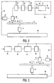
- Figures 1a, 1b, a record carrier;
- Figure 2, a playback device;
- Figure 3, a recording device;
- Figure 4, a file system for use with the invention;
- Figure 5, a storage arrangement for the invention;
- Figure 6, a detailed track organization.
- Fig. 1a shows a disc-
shaped record carrier 11 withcentral hole 10 andphysical track 19 arranged in a spiral pattern of turns to form substantially parallel structures on an information layer. The carrier may be an optical disc with a recordable or a prerecorded information layer. CD-R, CD-RW, and DVD-RAM are recordable; audio CD is prerecorded. Prerecorded discs can be manufactured by first recording a master disc and later pressing copies.Physical Track 19 is indicated by a pre-embossed physical structure. The physical track may have pregroove 14 to allow a read/write head to follow it while scanning. The information is recorded on the information layer by optically detectable marks along the physical track, e.g. pits and lands. - Fig. 1b is a cross-section along the line b-b of a
recordable carrier 11, whereintransparent substrate 15 carriesrecording layer 16 andprotective layer 17. Pregroove 14 may be effected as an indentation, an elevation, or as a material property deviating from its surroundings. - For user convenience, the audio information on the carrier has been subdivided into items that often have a duration of a few minutes, e.g. songs of an album or movements of a symphony; hereinafter, these will be called (logical) tracks, in contradistinction to the physical track of Figure 1. The carrier will often contain access information for identifying the items, such as a Table Of Contents (TOC) included in a file system like ISO 9660 for CD-ROM. The access information may include playing time, start address and song title for each item.
- The audio information is recorded in digital representation after analog to digital conversion. Examples of A/D conversion are PCM 16-bit per sample at 44.1 kHz known from CD audio and 1 bit Sigma Delta modulation at a high oversampling rate e.g. 64 x Fs called Bitstream. The latter, high quality, method allows to choose between high quality decoding and low quality decoding. Reference therefor is had to the publications 'A digital decimating filter for analog-to-digital conversion of hi-fi audio signals', by J.J. van der Kam, document D5 infra, and 'A higher order topology for interpolative modulators for oversampling A/D converters', by Kirk C.H. Chao et al, document D6. After A/D conversion, digital audio may be compressed to variable bitrate audio data for recording. The compressed audio data will be read from the carrier at such a speed, that after decompression substantially the original timescale is restored when reproducing the audio information continuously. Hence the compressed data must be retrieved from the carrier at a speed dependent on the varying bitrate. The data is retrieved from the record carrier at so-called transfer speed, i.e. the speed of transferring data bytes from the carrier to a de-compressor. The record carrier may have a constant spatial data density to give the highest data storage density. In such system the transfer speed is proportional to the relative linear speed between the medium and the read/write head.
- Figure 2 shows a playback device for
reading carrier 11 of the type shown in Figure 1. The device has drive means 21 for rotatingcarrier 11 and readhead 22 for scanning the physical track. Positioning meanseffect 25 coarse radial positioning of readhead 22. The read head comprises a known optical system with a radiation source for generatingbeam 24 that is guided through optical elements and focused onspot 23 on an information layer. The read head further comprises a focusing actuator for moving the focus of theradiation 24 along the optical axis of the beam and a tracking actuator for fine positioning ofspot 23 in a radial direction on the centre of the physical track. This actuator may comprise coils to move an optical element or may be arranged to change the angle of a reflecting element. The radiation reflected by the information layer is detected by a known detector in theread head 22, e.g. a four-quadrant diode, to generate a read signal and further detector signals, including tracking error and focusing error signals for the tracking and focusing actuators, respectively. To retrieve the data, the read signal is processed byreading means 27 that may comprise a channel demodulator and an error corrector. The retrieved data is sent to data selection means 28 to select the compressed audio data to feedbuffer 29. The selection is based on data type indicators also recorded on the carrier, e.g. headers in a framed format. Frombuffer 29, the compressed audio data are sent to de-compressor 31 assignal 30. This signal may also be outputted to an external de-compressor. De-compressor 31 from the compressed audio data reproduces the original audio information onoutput 32. The de-compressor may be located in a stand-alone high quality audio digital toanalog convertor 33 in Figure 2. Alternatively, the buffer may be located before the data selection means.Buffer 29 may be positioned in a separate housing or may be combined with a buffer in the decompressor. The device furthermore hascontrol unit 20 for receiving control commands from a user or from a host computer not shown, and viacontrol lines 26 is connected to drive means 21, positioning means 25, reading means 27 and data selection means 28, and possibly also to buffer 29 for filling level control. To this end, thecontrol unit 20 may comprise digital control circuitry. - The art of audio compression and de-compression is known. After digitizing, audio may be compressed by analyzing the correlation in the signal, and producing parameters for fragments of a specified size. During de-compression the inverse process is used to reconstruct the original signal. If the original digitized signal is reconstructed exactly, the (de)-compression is loss-less, whereas lossy (de)-compression will not reproduce some details of the original signal that however are substantially undetectable to the human ear or eye. Most known systems for audio and video, such as MPEG, use lossy compression, but loss-less compression is used for computer data. Examples of audio (de)-compression may be found in D2, D3 and D4 hereinafter.
- Data selection means 28 will retrieve from the data read control information indicating the transfer speed profile, and further will discard any stuffing data, that had been added during recording according to the speed profile. When
control unit 20 must reproduce an audio item from the carrier, positioning means 25 will position the reading head on the portion of the track containing the TOC. The starting address and the speed profile for that item will then be retrieved from the TOC via the data selection means 28. Alternatively, the contents of the TOC are read only once and stored in a memory when the disc is inserted in the apparatus. For reproducing the item, the drive means 21 will rotate the record carrier at the speed indicated by the speed profile. The required rotation rate may be denoted as such in the speed profile for setting the drive means. Alternatively the speed profile may comprise a bitrate, and then the rotation rate can be calculated from the radial position of the item as based on the starting address, because the record carrier density parameters, like track pitch and bit length, are predetermined and known to the playback device, usually from a standard. Next, the rotation rate can be derived from the bitrate and said radial position. - To provide continuous reproduction without buffer underflow or overflow, the transfer speed is coupled to the reproduction speed of the D/A converter, i.e. to the bitrate after decompression. The apparatus may thereto comprise a reference frequency source to control the decompressor and the rotation rate may be set in dependence of reference frequency and speed profile. The rotation rate may also be adjusted using the average filling level of the
buffer 29, e.g. decreasing the rotation rate if the buffer is more than 50% full on average. - Fig. 3 shows a recording device for writing information on a
carrier 11 of a type that is (re)writable. During writing, marks representing the information are formed on the record carrier. The marks may be in any optically readable form, e.g. in the form of areas whose reflection coefficient differs from their surroundings, through recording in materials such as dye, alloy or phase change, or as areas with a different magnetization direction from their surroundings. Writing and reading information for recording on optical disks and usable rules for formatting, error correcting and channel coding, are well-known, e.g. from the CD system. Marks may be formed through aspot 23 generated on the recording layer via abeam 24 of electromagnetic laser radiation. The recording device comprises similar basic elements as described with reference to Figure 2, i.e.control unit 20, drive means 21 and positioning means 25, but it has adistinctive write head 39. Audio information is presented on the input of compression means 35, which may be placed in a separate housing. Suitable compression has been described in D2, D3 and D4. The variable bitrate compressed audio on the output of compression means 35 is sent to buffer 36. Frombuffer 36 the data is sent to combiningmeans 37 for adding stuffing data and further control data. The total data stream is passed to writing means 38 for recording. Writehead 39 is fed by writingmeans 38 that may comprise a formatter, an error encoder and a channel modulator. The data presented to the input of writing means 38 are distributed over logical and physical sectors according to formatting and encoding rules and converted into a write signal for thewrite head 39.Unit 20 is arranged to controlbuffer 36, data combination means 37 and writing means 38 viacontrol lines 26 and for executing the positioning procedure as described above for the reading apparatus. The recording apparatus may also allow reading by having the features of a playback apparatus and a combined write/read head. - Figure 4 shows a file system for use with the invention, for which in principle various different options are feasible. Preferably, the storage medium should be based on the UDF or on the ISO 9660 file system. In an alternative case no file system would be present, and all relevant sector spaces should be kept empty.
- If a file system is present however, all audio will be stored in Audio Files located in SubDirectory SCD_AUDIO. Figure 4 shows the hierarchy to be based on
ROOT file 50 pointing to varioussubaltern files identical MASTER.TOCs 52 will be discussed hereinafter. Furthermore, there is a2C_AUDIO file 54. This points to mutually identical Area TOCs 2C_AREA1/2.TOC tracks TRACKn.2CH 60, and also to Area file2C_TAREA.2CH 61. Further, there isMC_AUDIO file 56. This points to mutually identicalTOCs MC.TOC tracks TRACKn.MCH 64, and also to Area fileMC_TAREA.MCH 65. In consequence, the tracks may be accessed either via the associated TOCs, or via a file system that has TOC and sub-TOCS as directories. Thefiles file item 67 may indicate stored pictorial information. - Figure 5 shows an exemplary storage arrangement for use with the invention, which has been shown as a single serial representation. Along the horizontal axis, the following items are evident.
Item 120 is a Lead-in that is used for mutually synchronizing a reader and the driving of the medium.File System 122 represents what has been disclosed with respect to Figure 4.MASTER TOC item 124 may be configured along standard procedures and pertains to subsequentitems Stereo Area 126, andMulti-channel Audio Item 128, and if necessary also toExtra Data Item 130. The lengths of these three areas need not be standardized, because various different amounts of information may be present. With respect to the audio areas, the audio track areas proper, as well as the associated SUB_TOCs are included. Apart from the disclosure hereinafter, the contents ofitems -
Item 130 represents Extra Data Information that may be defined in a conventional standard. Lead-Out Information 132 is in particular used for search operations. Its tracks do not contain other information than track numbers and addresses. The number of lead-out tracks may cover a ring of some 0.5 to 1 millimeter wide. According to the above, the stored information may be accessed either via the file system as laid down initem 122 or via the TOC structure laid down initem 124. - Any of the single or
plural Master TOCs 124 will starts at respective uniformly standardized offset position from the start of the Lead-in area, such as byte number 500 for the first Master TOC. In the embodiment, a Master-TOC measures only one standard-size sector and primarily contains pointers to the various Sub-TOCs or Area-TOCs to be disclosed hereinafter. A preferred syntax of the Master-TOC is as follows: - 1. A 16-byte Signature identifies a Master-TOC, such as by "SACD Master TOC ". The signature contains three space characters; the apostrophes are not part of the definition.
- 2. A 2-byte Spec_version indicates the version number of the format used in the disc.
- 3. A 14-byte Space has been reserved, such as for alignment stuffing.
- 4. A 4-byte integer 2CH-start_address contains the logical address of the first sector of the stereo area.
- 5. A 4-byte integer 2CH-end_address contains the logical address of the last sector of the stereo area.
- 6. A 4-byte integer MC-start_address contains the logical address of the first sector of the Multi channel area.
- 7. A 4-byte integer MC-end_address contains the logical address of the last sector of the Multi channel area.
- 8. A 4-byte integer Extra_data_start_address contains the logical address of the first sector of the Extra Data area.
- 9. A 4-byte integer Extra_data_end_address contains the logical address of the last sector of the Extra Data area.
- The information for the above totals 56 bytes. Extra features may be added to the Master-TOC. If a certain area is absent, the associated start and end addresses have value zero.
- Next,
items - 1. A 16-byte Signature identifies the Sub-TOC in question such as by "SACD stereo TOC " for a stereo audio area and "SACD MC TOC " for a Multi Channel audio area, the number of bytes being attained by adding trailing space characters.
- 2. A 2-byte Spec_version indicates the version number of the format used in the disc.
- 3. A 4-byte Sub_TOC_length indicates the number of bytes present in the actual TOC.
- 4. A 10-byte Space may be reserved for alignment stuffing.
- 5. A variable size set of /* Disc Parameters */ may be given, such as a Name of an Album() and a Name of a Catalogue().
- 6. A 4-byte disc_play_time indicates the total linear playing time of the disc expressed as a time code.
- 7. A 4-byte disc_name_pointer indicates the offset in bytes from the start of the Sub_TOC in question to the start of the disc_name() field. If this value is 0, it indicates that the disc_name() field is absent.
- 8. A 4-byte disc_date_pointer indicates the offset in bytes from the start of the Sub_TOC in question to the start of the disc_date() field. If this value is 0, it indicates that the disc_date() field is absent.
- 9. A 4-byte disc_copyright_pointer indicates the offset in bytes from the start of the Sub_TOC in question to the start of the disc_copyright() field. This value may be 0, to indicate that the disc_copyright() field is absent.
- 10. A 4-byte disc_publisher _pointer indicates the offset in bytes from the start of the Sub_TOC in question to the start of the disc_publisher() field. This value may be 0 to indicate that the disc_publisher() field is absent.
- 11. A variable size Track_List() may for each one of a plurality of audio tracks contain offset information to the start of the TOC in question, plus various further items that may be interesting to a listener, such as the name of track.
- A Track_List_1 contains:
- 12. An 8-byte Track_List_1_Signature identifying the sector with Track_List_1.
- 13. A 4-byte Track_Start_Address (tno) for all audio tracks with tracknumber tno in the current Audio Area containing the logical address of the first sector of the track.
- 14. A 4-byte Track_length (tno) for all audio tracks with tracknumber tno in the current Audio Area containing the length in sectors of the track.
- A Track_List_2 contains:
- 15. An 8-byte Track_List_2_Signature identifying the sector with Track_List_2.
- 16. A Track_Start_Time_Code (tno) for all audio tracks with tracknumber tno giving the start Time_Code of the track.
- 17. A Track_Time_Length (tno) for all audio tracks with tracknumber tno giving the playing time of the track.
- Figure 6 gives a detailed track organization, in particular, regarding the two categories of
files audio tracks - For each track A, the start location length and other information is given in the Area-TOC of the Audio Area where the track belongs to. The storage area of the tracks A and the pause intervals P, as represented in Figure 6 by
indication 148, contains a Time_Code. The Time_Code starts with zero at the start of the pause interval P. The Time_Code increments in steps of 1/75 seconds to the end of the storage are 148. A time unit of 1/75 second is called a frame. The Time_Code is encoded in multiplexed frames. All tracks A as well as all pause intervals P in thestorage area 148 are consecutively numbered starting with one. - Now, for accessing only a single separated track, such as for computer processing, or playing in an arbitrary order, usually only the audio proper will be relevant. In such situation, reproduction may forego the pauses or set them in an independent manner. In consequence, files 60, 64 in Figure 4 will exclusively point to the associated track audio parts taken in isolation. Such has in Figure 6 been represented by
indication 148, that covers exclusively audio. On the other hand, another mode of use is to play the area sector-by-sector. This may in principle be done without reference to any file system at all. The inventors have however recognized that for reasons of consistence, a file system would be appropriate, but should not overlook pauses for esthetic or other perceptive arguments. Therefore, a separate file has been assigned to the area as a whole, inclusive of the pauses, which has been symbolized by theadditional indication 150, and included initems -
- (D1) Research Disclosure No. 36411, August 1994, p. 412-413.
- (D2) PCT/IB97/01156 (PHN 16.452), 1 bit ADC and lossless compression of audio
- (D3) PCT/EB97/01303 (PHN 16.405), Audio compressor
- (D4) EP-A 402,973 (PHN 13.241), Audio compression
- (D5) J.J. van der Kam 'A digital decimating filter for analog-to-digital conversion of hi-fi audio signals', Philips Techn. Rev. 42, No 6/7, April 1986, pp. 230-8.
- (D6) Kirk C.H. Chao et al, 'A higher order topology for interpolative modulators for oversampling A/D converters', IEEE Tr. on Circuits and Systems,
Vol 37, No 3, March 1990, pp. 309-18.
Claims (7)
- A method for storing audio information on a disc like storage medium (11) of the optically readable type through a Table-of-Contents (TOC) mechanism for therein specifying an actual location of various audio tracks(140,142,144,146) on said medium (11),
the Table-of-Contents (TOC) (2C_AREA1.TOC...., MC_AREA1.TOC...) comprising a list of entries (Track_List_1, Track_List_2) with a start time (Track_Start_Time_Code) and / or a start address (Track_Start_Address) of each audio track (tno),
being characterized by assigning in addition to the TOC mechanism furthermore a multi-level file-based access mechanism to the audio information comprising at a higher level
audio files (54,56) assigned to a particular audio area (126,128) pointing to files (58 ... 65)) at a next-lower level, comprising
files (60,64) that point separately to areas where exclusively the audio tracks (A) are located,
one or more files (58,59,62,63) that point to areas where associated entries of the Table-of-Contents (TOC) are located, and
a comprehensive file (61, 65) that points to the area where audio tracks (A) as well as interposed pause intervals (P) between the latter audio tracks (A) are located. - A method as claimed in claim 1, wherein the pause intervals contain time-information (Time-Code) starting with zero at the start of the pause interval P.
- A method as claimed in claim 2, whilst furthermore providing separate said comprehensive files (61,65) with respect to two-channel audio and with respect to multi-channel audio, respectively.
- A disc like storage medium (11) of the optically readable type, comprising audio information (140, 142, 144, 146) and a Table-of-Content (TOC) (2C_AREA1.TOC...., MC_AREA1.TOC...) for therein specifying an actual location of various audio tracks (140,142,144,146) on said medium (11),
the Table-of-Contents (TOC) comprising a list of entries (Track_List_1, Track_List_2) with a start time (Track_Start_Time_Code) and / or a start address (Track_Start_Address) of each audio track (tno),
characterized in that,
said medium (11) is provided with a multi-level file-based access mechanism to the audio information, comprising at a higher level,
audio files (54,56) assigned to a particular audio area (126,128) pointing to files (58...65) at a next-lower level, comprising
files (60,64) that point separately to areas where exclusively the audio tracks (A) are located,
one or more files (58,59,62,63) that point to areas where associated entries of the Table-of-Contents (TOC) are located, and
a comprehensive file (61, 65) that points to the area where audio tracks (A) as well as interposed pause intervals (P) between the latter audio tracks (A) are located. - A disc like storage medium as claimed in claim 4, wherein the pause intervals contain time-information (Time-Code) starting with zero at the start of the pause interval P.
- A disc like storage medium as claimed in claim 5, comprising separate comprehensive files (61,65) with respect to two-channel audio and with respect to multi-channel audio, respectively.
- A reading device for reading information in a disc like storage medium (11) as claimed in claim 4, comprising
optical access means (22,25), disc drive means (21) for driving the disc track along said optical access means (22,25) for retrieving a read signal from the disc, reading means (27) for processing the read signal and control means (20) for controlling said means (21,22,25,27), characterized in that,
the control means (20) are adapted to determine the sizes of the pauses (P) from the comprehensive file (61,65) and said associated entries of the Table-of-Contents (2C_AREA.TOC, MC_AREA.TOC).
Priority Applications (1)
| Application Number | Priority Date | Filing Date | Title |
|---|---|---|---|
| EP99921084A EP1034540B1 (en) | 1998-06-10 | 1999-06-03 | A method for storing audio-centered information using higher level audio files and lower level audio item indicating files, a device for reading and/or storing such information and a record carrier |
Applications Claiming Priority (6)
| Application Number | Priority Date | Filing Date | Title |
|---|---|---|---|
| EP98201939 | 1998-06-10 | ||
| EP98201939 | 1998-06-10 | ||
| EP99200777 | 1999-03-15 | ||
| EP99200777 | 1999-03-15 | ||
| EP99921084A EP1034540B1 (en) | 1998-06-10 | 1999-06-03 | A method for storing audio-centered information using higher level audio files and lower level audio item indicating files, a device for reading and/or storing such information and a record carrier |
| PCT/IB1999/001018 WO1999065034A2 (en) | 1998-06-10 | 1999-06-03 | A method for storing audio-centered information using higher level audio files and lower level audio item indicating files, a device for reading and/or storing such information and a record carrier |
Publications (2)
| Publication Number | Publication Date |
|---|---|
| EP1034540A2 EP1034540A2 (en) | 2000-09-13 |
| EP1034540B1 true EP1034540B1 (en) | 2007-02-28 |
Family
ID=26150422
Family Applications (1)
| Application Number | Title | Priority Date | Filing Date |
|---|---|---|---|
| EP99921084A Expired - Lifetime EP1034540B1 (en) | 1998-06-10 | 1999-06-03 | A method for storing audio-centered information using higher level audio files and lower level audio item indicating files, a device for reading and/or storing such information and a record carrier |
Country Status (15)
| Country | Link |
|---|---|
| US (1) | US6633515B1 (en) |
| EP (1) | EP1034540B1 (en) |
| JP (1) | JP3918038B2 (en) |
| KR (1) | KR100701255B1 (en) |
| CN (1) | CN1275235A (en) |
| AT (1) | ATE355593T1 (en) |
| AU (1) | AU3843099A (en) |
| BG (1) | BG63926B1 (en) |
| BR (1) | BR9906497A (en) |
| DE (1) | DE69935308T2 (en) |
| IL (1) | IL134434A0 (en) |
| MY (1) | MY133145A (en) |
| PL (1) | PL338952A1 (en) |
| TW (1) | TW439055B (en) |
| WO (1) | WO1999065034A2 (en) |
Families Citing this family (9)
| Publication number | Priority date | Publication date | Assignee | Title |
|---|---|---|---|---|
| TR199901788T1 (en) * | 1997-11-29 | 2000-05-22 | Koninklijke Philips Electronics N.V. | Storing audio-centric information with a table of contents (TOC) mechanism as well as a file-based access mechanism via a ROOT filing containing the highest TOC filing A method and device for and a unitary storage medium containing this information. |
| JPH11259980A (en) * | 1998-03-09 | 1999-09-24 | Pioneer Electron Corp | Information recording device |
| KR100601598B1 (en) * | 1998-06-15 | 2006-07-14 | 삼성전자주식회사 | Recording medium storing write protection information and write protecting method |
| US6901038B2 (en) * | 2000-06-02 | 2005-05-31 | Samsung Electronics Co., Ltd. | Audio recording medium, methods of recording data on and reproducing data from the recording medium, and recording and reproducing apparatuses therefor |
| US7114028B1 (en) * | 2002-05-21 | 2006-09-26 | Sonic Solutions | Method of automatically formatting and pseudo-mounting a removable media |
| JP4228288B2 (en) * | 2003-06-11 | 2009-02-25 | ソニー株式会社 | Recording control apparatus and method, program, and data recording method |
| US7765104B2 (en) * | 2005-08-30 | 2010-07-27 | Lg Electronics Inc. | Slot position coding of residual signals of spatial audio coding application |
| JPWO2007049743A1 (en) * | 2005-10-27 | 2009-04-30 | パイオニア株式会社 | Information recording medium, information recording apparatus and method, and computer program |
| CN109766215B (en) * | 2018-12-06 | 2022-03-25 | 合肥联宝信息技术有限公司 | Data processing method and device |
Family Cites Families (14)
| Publication number | Priority date | Publication date | Assignee | Title |
|---|---|---|---|---|
| NL9000338A (en) | 1989-06-02 | 1991-01-02 | Koninkl Philips Electronics Nv | DIGITAL TRANSMISSION SYSTEM, TRANSMITTER AND RECEIVER FOR USE IN THE TRANSMISSION SYSTEM AND RECORD CARRIED OUT WITH THE TRANSMITTER IN THE FORM OF A RECORDING DEVICE. |
| US5280468A (en) * | 1989-11-16 | 1994-01-18 | Olympus Optical Co., Ltd. | Optical recording medium |
| JP2822525B2 (en) * | 1990-01-12 | 1998-11-11 | ソニー株式会社 | Recording medium reproducing apparatus, reproducing method and search method |
| JPH04186447A (en) * | 1990-11-21 | 1992-07-03 | Canon Inc | Directory management system |
| DE69429651T2 (en) * | 1993-10-18 | 2002-09-19 | Sony Corp | INFORMATION MANAGEMENT PROCEDURE, DATA RECORDING CARRIERS AND PROCEDURES, INFORMATION RECOVERY PROCEDURE AND DEVICE |
| JP3693742B2 (en) * | 1996-03-13 | 2005-09-07 | 株式会社リコー | Information recording medium |
| JP3707137B2 (en) * | 1996-07-04 | 2005-10-19 | ソニー株式会社 | Recording medium and playback device |
| WO1998007149A1 (en) * | 1996-08-14 | 1998-02-19 | Sony Corporation | Device and method for reproducing data on disk |
| US6269338B1 (en) | 1996-10-10 | 2001-07-31 | U.S. Philips Corporation | Data compression and expansion of an audio signal |
| WO1998020488A2 (en) | 1996-11-07 | 1998-05-14 | Philips Electronics N.V. | Data processing of a bitstream signal |
| ID22712A (en) * | 1997-11-29 | 1999-12-09 | Koninkl Philips Electronics Nv | METHOD OF CENTRALIZED AUDIO, PIRANTI STORAGE METHOD USING THE MECHANISM AND THE UNITER STORAGE MEDIA CONTAINING THE MECHANISM |
| TR199901788T1 (en) * | 1997-11-29 | 2000-05-22 | Koninklijke Philips Electronics N.V. | Storing audio-centric information with a table of contents (TOC) mechanism as well as a file-based access mechanism via a ROOT filing containing the highest TOC filing A method and device for and a unitary storage medium containing this information. |
| US6370090B1 (en) * | 1998-06-10 | 2002-04-09 | U.S. Philips Corporation | Method, device, and information structure for storing audio-centered information with a multi-level table-of-contents (toc) mechanism and doubling of area-tocs, a device for use with such mechanism and a unitary storage medium having such mechanism |
| JP4388701B2 (en) * | 1998-11-16 | 2009-12-24 | コーニンクレッカ フィリップス エレクトロニクス エヌ ヴィ | Method and apparatus for recording real-time information |
-
1999
- 1999-06-03 JP JP2000553958A patent/JP3918038B2/en not_active Expired - Lifetime
- 1999-06-03 AT AT99921084T patent/ATE355593T1/en not_active IP Right Cessation
- 1999-06-03 PL PL99338952A patent/PL338952A1/en unknown
- 1999-06-03 DE DE69935308T patent/DE69935308T2/en not_active Expired - Lifetime
- 1999-06-03 CN CN99801326A patent/CN1275235A/en active Pending
- 1999-06-03 KR KR1020007001316A patent/KR100701255B1/en not_active IP Right Cessation
- 1999-06-03 BR BR9906497-9A patent/BR9906497A/en not_active Application Discontinuation
- 1999-06-03 IL IL13443499A patent/IL134434A0/en unknown
- 1999-06-03 AU AU38430/99A patent/AU3843099A/en not_active Abandoned
- 1999-06-03 EP EP99921084A patent/EP1034540B1/en not_active Expired - Lifetime
- 1999-06-03 WO PCT/IB1999/001018 patent/WO1999065034A2/en active IP Right Grant
- 1999-06-08 MY MYPI99002326A patent/MY133145A/en unknown
- 1999-06-08 US US09/328,023 patent/US6633515B1/en not_active Expired - Lifetime
- 1999-07-20 TW TW088112303A patent/TW439055B/en not_active IP Right Cessation
-
2000
- 2000-02-09 BG BG104145A patent/BG63926B1/en unknown
Also Published As
| Publication number | Publication date |
|---|---|
| TW439055B (en) | 2001-06-07 |
| JP2002518774A (en) | 2002-06-25 |
| DE69935308D1 (en) | 2007-04-12 |
| PL338952A1 (en) | 2000-12-04 |
| DE69935308T2 (en) | 2007-10-31 |
| EP1034540A2 (en) | 2000-09-13 |
| MY133145A (en) | 2007-10-31 |
| AU3843099A (en) | 1999-12-30 |
| BG63926B1 (en) | 2003-06-30 |
| KR20010022719A (en) | 2001-03-26 |
| BR9906497A (en) | 2000-09-26 |
| CN1275235A (en) | 2000-11-29 |
| WO1999065034A2 (en) | 1999-12-16 |
| US6633515B1 (en) | 2003-10-14 |
| KR100701255B1 (en) | 2007-03-29 |
| ATE355593T1 (en) | 2006-03-15 |
| IL134434A0 (en) | 2001-04-30 |
| JP3918038B2 (en) | 2007-05-23 |
| WO1999065034A3 (en) | 2000-04-20 |
| BG104145A (en) | 2000-06-30 |
Similar Documents
| Publication | Publication Date | Title |
|---|---|---|
| US8427910B2 (en) | Storing audio-centered information with a multi-level table-of-contents (TOC) mechanism having redundant sub-TOCs | |
| US7649813B2 (en) | Accessing audio-centered information using a multilevel table-of-contents mechanism and directory structures | |
| EP1034540B1 (en) | A method for storing audio-centered information using higher level audio files and lower level audio item indicating files, a device for reading and/or storing such information and a record carrier | |
| US8531923B2 (en) | Method for storing audio-centered information with a multi-level table-of-contents (TOC) mechanism with one master-TOC and sub-TOCs for various audio formats, a device for use with such mechanism and a unitary storage medium containing such mechanism | |
| US6661762B1 (en) | Method and device for interfacing variable-rate sampled digital audio information to a string of uniform-sized blocks, and a unitary medium so produced by a write-interfacing | |
| MXPA00001333A (en) | A method for storing audio-centered information using higher level audio files and lower level audio item indicating files, a device for reading and/or storing such information and a record carrier |
Legal Events
| Date | Code | Title | Description |
|---|---|---|---|
| PUAI | Public reference made under article 153(3) epc to a published international application that has entered the european phase |
Free format text: ORIGINAL CODE: 0009012 |
|
| 17P | Request for examination filed |
Effective date: 20000310 |
|
| AK | Designated contracting states |
Kind code of ref document: A2 Designated state(s): AT BE DE DK ES FR GB GR IE IT NL PT SE |
|
| 17Q | First examination report despatched |
Effective date: 20040311 |
|
| GRAP | Despatch of communication of intention to grant a patent |
Free format text: ORIGINAL CODE: EPIDOSNIGR1 |
|
| GRAS | Grant fee paid |
Free format text: ORIGINAL CODE: EPIDOSNIGR3 |
|
| GRAA | (expected) grant |
Free format text: ORIGINAL CODE: 0009210 |
|
| AK | Designated contracting states |
Kind code of ref document: B1 Designated state(s): AT BE DE DK ES FR GB GR IE IT NL PT SE |
|
| PG25 | Lapsed in a contracting state [announced via postgrant information from national office to epo] |
Ref country code: NL Free format text: LAPSE BECAUSE OF FAILURE TO SUBMIT A TRANSLATION OF THE DESCRIPTION OR TO PAY THE FEE WITHIN THE PRESCRIBED TIME-LIMIT Effective date: 20070228 Ref country code: DK Free format text: LAPSE BECAUSE OF FAILURE TO SUBMIT A TRANSLATION OF THE DESCRIPTION OR TO PAY THE FEE WITHIN THE PRESCRIBED TIME-LIMIT Effective date: 20070228 Ref country code: BE Free format text: LAPSE BECAUSE OF FAILURE TO SUBMIT A TRANSLATION OF THE DESCRIPTION OR TO PAY THE FEE WITHIN THE PRESCRIBED TIME-LIMIT Effective date: 20070228 Ref country code: AT Free format text: LAPSE BECAUSE OF FAILURE TO SUBMIT A TRANSLATION OF THE DESCRIPTION OR TO PAY THE FEE WITHIN THE PRESCRIBED TIME-LIMIT Effective date: 20070228 |
|
| REG | Reference to a national code |
Ref country code: GB Ref legal event code: FG4D |
|
| REF | Corresponds to: |
Ref document number: 69935308 Country of ref document: DE Date of ref document: 20070412 Kind code of ref document: P |
|
| REG | Reference to a national code |
Ref country code: IE Ref legal event code: FG4D |
|
| PG25 | Lapsed in a contracting state [announced via postgrant information from national office to epo] |
Ref country code: SE Free format text: LAPSE BECAUSE OF FAILURE TO SUBMIT A TRANSLATION OF THE DESCRIPTION OR TO PAY THE FEE WITHIN THE PRESCRIBED TIME-LIMIT Effective date: 20070531 |
|
| PG25 | Lapsed in a contracting state [announced via postgrant information from national office to epo] |
Ref country code: ES Free format text: LAPSE BECAUSE OF FAILURE TO SUBMIT A TRANSLATION OF THE DESCRIPTION OR TO PAY THE FEE WITHIN THE PRESCRIBED TIME-LIMIT Effective date: 20070608 |
|
| PG25 | Lapsed in a contracting state [announced via postgrant information from national office to epo] |
Ref country code: PT Free format text: LAPSE BECAUSE OF FAILURE TO SUBMIT A TRANSLATION OF THE DESCRIPTION OR TO PAY THE FEE WITHIN THE PRESCRIBED TIME-LIMIT Effective date: 20070730 |
|
| NLV1 | Nl: lapsed or annulled due to failure to fulfill the requirements of art. 29p and 29m of the patents act | ||
| ET | Fr: translation filed | ||
| PLBE | No opposition filed within time limit |
Free format text: ORIGINAL CODE: 0009261 |
|
| STAA | Information on the status of an ep patent application or granted ep patent |
Free format text: STATUS: NO OPPOSITION FILED WITHIN TIME LIMIT |
|
| 26N | No opposition filed |
Effective date: 20071129 |
|
| PG25 | Lapsed in a contracting state [announced via postgrant information from national office to epo] |
Ref country code: IT Free format text: LAPSE BECAUSE OF FAILURE TO SUBMIT A TRANSLATION OF THE DESCRIPTION OR TO PAY THE FEE WITHIN THE PRESCRIBED TIME-LIMIT Effective date: 20070228 Ref country code: GR Free format text: LAPSE BECAUSE OF FAILURE TO SUBMIT A TRANSLATION OF THE DESCRIPTION OR TO PAY THE FEE WITHIN THE PRESCRIBED TIME-LIMIT Effective date: 20070529 |
|
| PG25 | Lapsed in a contracting state [announced via postgrant information from national office to epo] |
Ref country code: IE Free format text: LAPSE BECAUSE OF NON-PAYMENT OF DUE FEES Effective date: 20070605 |
|
| REG | Reference to a national code |
Ref country code: DE Ref legal event code: R082 Ref document number: 69935308 Country of ref document: DE Representative=s name: MEISSNER BOLTE PATENTANWAELTE RECHTSANWAELTE P, DE Effective date: 20140327 Ref country code: DE Ref legal event code: R082 Ref document number: 69935308 Country of ref document: DE Representative=s name: MEISSNER, BOLTE & PARTNER GBR, DE Effective date: 20140327 Ref country code: DE Ref legal event code: R081 Ref document number: 69935308 Country of ref document: DE Owner name: KONINKLIJKE PHILIPS N.V., NL Free format text: FORMER OWNERS: KONINKLIJKE PHILIPS ELECTRONICS N.V., EINDHOVEN, NL; PHILIPS AB, STOCKHOLM, SE Effective date: 20140327 Ref country code: DE Ref legal event code: R081 Ref document number: 69935308 Country of ref document: DE Owner name: PHILIPS AB, SE Free format text: FORMER OWNERS: KONINKLIJKE PHILIPS ELECTRONICS N.V., EINDHOVEN, NL; PHILIPS AB, STOCKHOLM, SE Effective date: 20140327 Ref country code: DE Ref legal event code: R081 Ref document number: 69935308 Country of ref document: DE Owner name: PHILIPS AB, SE Free format text: FORMER OWNER: KONINKLIJKE PHILIPS ELECTRONICS, PHILIPS AB, , SE Effective date: 20140327 Ref country code: DE Ref legal event code: R081 Ref document number: 69935308 Country of ref document: DE Owner name: KONINKLIJKE PHILIPS N.V., NL Free format text: FORMER OWNER: KONINKLIJKE PHILIPS ELECTRONICS, PHILIPS AB, , SE Effective date: 20140327 |
|
| REG | Reference to a national code |
Ref country code: FR Ref legal event code: CD Owner name: KONINKLIJKE PHILIPS N.V., NL Effective date: 20141126 Ref country code: FR Ref legal event code: CA Effective date: 20141126 |
|
| REG | Reference to a national code |
Ref country code: FR Ref legal event code: PLFP Year of fee payment: 18 |
|
| REG | Reference to a national code |
Ref country code: FR Ref legal event code: PLFP Year of fee payment: 19 |
|
| REG | Reference to a national code |
Ref country code: FR Ref legal event code: PLFP Year of fee payment: 20 |
|
| PGFP | Annual fee paid to national office [announced via postgrant information from national office to epo] |
Ref country code: FR Payment date: 20180629 Year of fee payment: 20 |
|
| PGFP | Annual fee paid to national office [announced via postgrant information from national office to epo] |
Ref country code: GB Payment date: 20180629 Year of fee payment: 20 Ref country code: DE Payment date: 20180831 Year of fee payment: 20 |
|
| REG | Reference to a national code |
Ref country code: DE Ref legal event code: R071 Ref document number: 69935308 Country of ref document: DE |
|
| REG | Reference to a national code |
Ref country code: GB Ref legal event code: PE20 Expiry date: 20190602 |
|
| PG25 | Lapsed in a contracting state [announced via postgrant information from national office to epo] |
Ref country code: GB Free format text: LAPSE BECAUSE OF EXPIRATION OF PROTECTION Effective date: 20190602 |