EP1033875A2 - Recording and reproducing apparatus - Google Patents
Recording and reproducing apparatus Download PDFInfo
- Publication number
- EP1033875A2 EP1033875A2 EP00301377A EP00301377A EP1033875A2 EP 1033875 A2 EP1033875 A2 EP 1033875A2 EP 00301377 A EP00301377 A EP 00301377A EP 00301377 A EP00301377 A EP 00301377A EP 1033875 A2 EP1033875 A2 EP 1033875A2
- Authority
- EP
- European Patent Office
- Prior art keywords
- data
- packet
- recording
- packets
- train
- Prior art date
- Legal status (The legal status is an assumption and is not a legal conclusion. Google has not performed a legal analysis and makes no representation as to the accuracy of the status listed.)
- Withdrawn
Links
- 230000005540 biological transmission Effects 0.000 claims abstract description 54
- 238000000034 method Methods 0.000 claims description 32
- 238000001514 detection method Methods 0.000 claims description 8
- 238000013500 data storage Methods 0.000 description 70
- 238000007726 management method Methods 0.000 description 28
- 230000015654 memory Effects 0.000 description 25
- 230000008569 process Effects 0.000 description 15
- 238000010586 diagram Methods 0.000 description 14
- 230000006870 function Effects 0.000 description 7
- 230000007306 turnover Effects 0.000 description 6
- 239000004065 semiconductor Substances 0.000 description 4
- 230000008859 change Effects 0.000 description 3
- 101001073193 Homo sapiens Pescadillo homolog Proteins 0.000 description 2
- 102100035816 Pescadillo homolog Human genes 0.000 description 2
- 230000003287 optical effect Effects 0.000 description 2
- 230000002035 prolonged effect Effects 0.000 description 2
- 230000004044 response Effects 0.000 description 2
- 101100244387 Candida albicans (strain SC5314 / ATCC MYA-2876) PMT6 gene Proteins 0.000 description 1
- 101100294638 Neosartorya fumigata (strain ATCC MYA-4609 / Af293 / CBS 101355 / FGSC A1100) NRPS8 gene Proteins 0.000 description 1
- 101150036326 PMT2 gene Proteins 0.000 description 1
- 101150024216 PMT3 gene Proteins 0.000 description 1
- 101100241858 Saccharomyces cerevisiae (strain ATCC 204508 / S288c) OAC1 gene Proteins 0.000 description 1
- 101100043108 Schizosaccharomyces pombe (strain 972 / ATCC 24843) spb1 gene Proteins 0.000 description 1
- 238000006243 chemical reaction Methods 0.000 description 1
- 101150092906 pmt1 gene Proteins 0.000 description 1
Images


Classifications
-
- G—PHYSICS
- G11—INFORMATION STORAGE
- G11B—INFORMATION STORAGE BASED ON RELATIVE MOVEMENT BETWEEN RECORD CARRIER AND TRANSDUCER
- G11B27/00—Editing; Indexing; Addressing; Timing or synchronising; Monitoring; Measuring tape travel
- G11B27/10—Indexing; Addressing; Timing or synchronising; Measuring tape travel
- G11B27/102—Programmed access in sequence to addressed parts of tracks of operating record carriers
- G11B27/105—Programmed access in sequence to addressed parts of tracks of operating record carriers of operating discs
-
- G—PHYSICS
- G11—INFORMATION STORAGE
- G11B—INFORMATION STORAGE BASED ON RELATIVE MOVEMENT BETWEEN RECORD CARRIER AND TRANSDUCER
- G11B27/00—Editing; Indexing; Addressing; Timing or synchronising; Monitoring; Measuring tape travel
- G11B27/10—Indexing; Addressing; Timing or synchronising; Measuring tape travel
- G11B27/11—Indexing; Addressing; Timing or synchronising; Measuring tape travel by using information not detectable on the record carrier
-
- G—PHYSICS
- G11—INFORMATION STORAGE
- G11B—INFORMATION STORAGE BASED ON RELATIVE MOVEMENT BETWEEN RECORD CARRIER AND TRANSDUCER
- G11B27/00—Editing; Indexing; Addressing; Timing or synchronising; Monitoring; Measuring tape travel
- G11B27/10—Indexing; Addressing; Timing or synchronising; Measuring tape travel
- G11B27/19—Indexing; Addressing; Timing or synchronising; Measuring tape travel by using information detectable on the record carrier
- G11B27/28—Indexing; Addressing; Timing or synchronising; Measuring tape travel by using information detectable on the record carrier by using information signals recorded by the same method as the main recording
- G11B27/32—Indexing; Addressing; Timing or synchronising; Measuring tape travel by using information detectable on the record carrier by using information signals recorded by the same method as the main recording on separate auxiliary tracks of the same or an auxiliary record carrier
- G11B27/327—Table of contents
- G11B27/329—Table of contents on a disc [VTOC]
-
- G—PHYSICS
- G11—INFORMATION STORAGE
- G11B—INFORMATION STORAGE BASED ON RELATIVE MOVEMENT BETWEEN RECORD CARRIER AND TRANSDUCER
- G11B27/00—Editing; Indexing; Addressing; Timing or synchronising; Monitoring; Measuring tape travel
- G11B27/10—Indexing; Addressing; Timing or synchronising; Measuring tape travel
- G11B27/34—Indicating arrangements
-
- H—ELECTRICITY
- H04—ELECTRIC COMMUNICATION TECHNIQUE
- H04N—PICTORIAL COMMUNICATION, e.g. TELEVISION
- H04N9/00—Details of colour television systems
- H04N9/79—Processing of colour television signals in connection with recording
- H04N9/80—Transformation of the television signal for recording, e.g. modulation, frequency changing; Inverse transformation for playback
- H04N9/804—Transformation of the television signal for recording, e.g. modulation, frequency changing; Inverse transformation for playback involving pulse code modulation of the colour picture signal components
- H04N9/8042—Transformation of the television signal for recording, e.g. modulation, frequency changing; Inverse transformation for playback involving pulse code modulation of the colour picture signal components involving data reduction
-
- G—PHYSICS
- G11—INFORMATION STORAGE
- G11B—INFORMATION STORAGE BASED ON RELATIVE MOVEMENT BETWEEN RECORD CARRIER AND TRANSDUCER
- G11B2220/00—Record carriers by type
- G11B2220/20—Disc-shaped record carriers
-
- G—PHYSICS
- G11—INFORMATION STORAGE
- G11B—INFORMATION STORAGE BASED ON RELATIVE MOVEMENT BETWEEN RECORD CARRIER AND TRANSDUCER
- G11B2220/00—Record carriers by type
- G11B2220/20—Disc-shaped record carriers
- G11B2220/25—Disc-shaped record carriers characterised in that the disc is based on a specific recording technology
- G11B2220/2525—Magneto-optical [MO] discs
-
- G—PHYSICS
- G11—INFORMATION STORAGE
- G11B—INFORMATION STORAGE BASED ON RELATIVE MOVEMENT BETWEEN RECORD CARRIER AND TRANSDUCER
- G11B2220/00—Record carriers by type
- G11B2220/60—Solid state media
- G11B2220/61—Solid state media wherein solid state memory is used for storing A/V content
-
- G—PHYSICS
- G11—INFORMATION STORAGE
- G11B—INFORMATION STORAGE BASED ON RELATIVE MOVEMENT BETWEEN RECORD CARRIER AND TRANSDUCER
- G11B2220/00—Record carriers by type
- G11B2220/60—Solid state media
- G11B2220/65—Solid state media wherein solid state memory is used for storing indexing information or metadata
-
- H—ELECTRICITY
- H04—ELECTRIC COMMUNICATION TECHNIQUE
- H04N—PICTORIAL COMMUNICATION, e.g. TELEVISION
- H04N9/00—Details of colour television systems
- H04N9/79—Processing of colour television signals in connection with recording
- H04N9/80—Transformation of the television signal for recording, e.g. modulation, frequency changing; Inverse transformation for playback
- H04N9/82—Transformation of the television signal for recording, e.g. modulation, frequency changing; Inverse transformation for playback the individual colour picture signal components being recorded simultaneously only
- H04N9/8205—Transformation of the television signal for recording, e.g. modulation, frequency changing; Inverse transformation for playback the individual colour picture signal components being recorded simultaneously only involving the multiplexing of an additional signal and the colour video signal
Definitions
- the present invention relates to a recording and reproducing apparatus, and more particularly to an apparatus for recording and reproducing television signals of a plurality of multiplexed programs each constituted of a plurality of packets.
- Digital television (hereinafter described as digital TV) broadcasting for broadcasting television signals as digital signals has been proposed recently, and in Japan, it is realized already as CS (Communication Satellite) broadcasting.
- Fig. 16 is a block diagram showing an apparatus for receiving digital TV broadcasting signals and recording and reproducing them.
- a digital TV signal received by a tuner 1601 is input via an input line 161 to an SW circuit 1603 and a data control circuit 1615.
- the data control circuit 1615 counts and stores a bit rate of the received data, and controls a data storage 1617 via a control line 1621-9 to store the received data via an input line 170.
- the data storage 1617 may be a hard disk, a large capacity semiconductor memory, an optical recording device, a magnetic recording device or the like.
- the received data While the received data is recorded, the received data may be divided, decoded and output. Namely, the received data input to the SW circuit 1603 via the input line 161 is selected by the SW circuit 1603 and input to a demultiplexer 1605 via an input line 162.
- the demultiplexer 1605 picks up only the data of a designated program in accordance with an ID in the received data, and divides it into a video data train and an audio data train.
- Video data is input via a video data line 163 to a video decoding unit 1607, and audio PES packet data is input via an audio PES data line 164 to an audio decoding unit 1609.
- the video decoding unit 1607 decodes the input video data train in a manner corresponding to the encoding executed when the data was transmitted, and outputs the decoded data to a video control unit 1611.
- the video control unit 1611 converts the decoded video data into a format suitable for external apparatus which is not shown, and outputs it via an output line 167.
- the audio decoding unit 1609 decodes the input audio data train in a manner corresponding to the encoding executed when the data was transmitted, and outputs the decoded data to an audio control unit 1613.
- the audio control unit 1613 converts the decoded audio data into a format suitable for an unrepresented external apparatus, and outputs it via an output line 168.
- the data control unit 1615 controls the data storage 1617 via the control line 1621 or the like to read the recorded digital TV data and outputs it to the SW circuit 1603 via an input line 169 at the bit rate stored in the data control unit 1615 when the TV data was received.
- the SW circuit 1603 selects the data input via the input line 169.
- the selected data is input to the demultiplexer 1605 via the input line 162.
- the operation to follow is the same as described above.
- the recording and reproducing apparatus described above is, however, associated with some problem. Namely, since the received data is recorded in or reproduced from the data storage on the program unit basis, when the data recorded in the data storage is reproduced, it is only possible either to reproduce the data from the start of a program or to reproduce the data from a proper position (in the unit of a management file of the data storage) intermediately of the recorded TS packet. The data cannot be reproduced from the position desired by a user, i.e., a so-called random access reproduction is impossible.
- a recording apparatus comprising: receiving means for receiving a data train multiplexing a plurality of programs each having a plurality of transmission packets; recording means for recording the received data train in a recording medium; and generating means for generating a recording location table of recording location data as to a recording location of a predetermined transmission packet in the storage medium among a plurality of transmission packets of each program in the data train.
- the invention is applied to an apparatus for receiving digital TV broadcasting signals and recording and reproducing them.
- digital TV signals of video data, audio data and other data are transmitted and received in the form of a transport stream (hereinafter described as TS) of MPEG 2.
- the basic data unit is a transport stream packet (hereinafter described as TS packet) having a fixed length of 188 bytes. All data is transmitted by this TS packet, irrespective of the types of data, such as video data, audio data and other data.
- One TS is generally made of a plurality of programs time divisionally multiplexed. These TSs same in number as the number of transponders transmitting at the same time.
- Fig. 2A shows an example of TS packet data of MPEG 2 in which three programs including video and audio data are encoded and time divisionally multiplexed in accordance with the formats defined in ISO/IEC 13818-1 (system), ISO/IEC 13818-2 (video) and ISO/IEO 13818-3 (audio).
- PAT is a program association table
- PMT1 is a program map table of a program number 1
- PMT2 is a program map table of a program number 2
- PMT3 is a program map table of a program number 3
- TS1-V is video TS packet data of the program number 1
- TS1-A is audio TS packet data of the program number 1
- TS2-V is video TS packet data of the program number 2
- TS2-A is audio TS packet data of the program number
- TS3-V is video TS packet data of the program number 3
- TS3-A is audio TS packet data of the program number 3.
- PAT and PMT are data called PSI (Program Specific Information) and are mainly used for simple tuning operation and program selecting operation.
- PAT Packet Identification
- PMT Packet Identification
- TS packet data has PID (Packet Identification) of 13 bits by which the contents of data can be identified.
- PAT describes PID of PMT
- PMT describes PID of each of various TS packets such as video, audio and other data of each program contained in TS.
- An example of PID is shown in Fig. 3.
- PID of each PMT is designated in a payload of PAT.
- PID of each of the video and audio packet data is designated by each PMT.
- Fig. 2B shows the structure of TS packet data.
- Each TS packet has data of 188 bytes including a TS header of top 24 bits, scramble control data of next 2 bits, and the payload such ad video and audio data of remaining bits.
- PES Packetized Elementary Stream
- video data of 1 GOP of 15 frames from an I picture to the B picture immediately before the next I picture is encoded, and one PES packet is constituted of the encoded video data of 1 GOP. Therefore, the start frame of each PES is always the I picture, i.e., intra-encoded.
- Fig. 2C shows three PES packets PES1 to PES3 constituting the video data of the program number 1. Generally, each of video and image data of one program is divided into a plurality of PES packets.
- Each PES packet has a different length, and as shown in Figs. 2C and 2D, one PES packet is divided into a plurality of TS packets which are then transmitted.
- a PES1 packet 201 is divided into a plurality of TS packets 207, 209, 211 and 213 which are then transmitted.
- Each PES packet data has one bit of unit start indicator data (payload_unit_start_indicator in ISO/IEC 13818-1) of the TS packet data IS.
- This unit start indicator data indicates that a new PES packet starts from the payload of the corresponding TS packet.
- data of one PES is the data in the payloads of the TS packets from the TS packet having the unit start indicator data "1" to the TS packet immediately before the next TS packet having the unit start indicator data "1".
- One set of PES packet data is constituted of the payload data of the TS packets including the TS packet having the unit start indicator data "1" and the succeeding n TS packets having the same PID.
- the transmission interval of TS packet data having the same PID and the unit start indicator bit or payload_unit_start_ indicator "1" is determined by television broadcasting institutes in the case of television broadcasting. In this embodiment, for the convenience of description, it is assumed that TS packet data is transmitted at an interval of 5 minutes. If one PES packet is constituted of encoded video data of 1 GOP as described above, the TS packet having the unit start indicator data "1" is essentially transmitted at an interval shorter than 5 minutes.
- Fig. 1 is a diagram showing a recording and reproducing apparatus according to an embodiment.
- a tuner 101 receives a digital TV signal in accordance with an instruction supplied via a control line 10-15, to output TS data including the program tuned by an operation unit 135 to an SW circuit 103.
- TS packet data of time divisionally multiplexed video and audio data of a plurality of programs such as shown in Figs. 2A to 2D is supplied to a TS input line 1.
- the SW circuit 103 supplies the TS packet data input via the TS input line 1 to a demultiplexer 105 via a TS data line 2.
- the demultiplexer 105 divides only the TS packet data having the designated PID supplied from a system control unit 129 via a control line 10-2.
- Each TS packet divided by the demultiplexer 129 is generally transferred as PES packet data defined in ISO/IEC 13818-1.
- Video packet data is supplied to a video decoding unit 109 via a video PES data line 3
- audio PES packet data is supplied via an audio PES data line 4 to an audio decoding unit 113.
- the video decoding unit 107 is controlled via a control line 10-3 by a system controller 129, and performs a decoding process of MPEG 2 for the input video PES packet data to output the decoded video data to a video control unit 109 via a decoded video data line 6.
- the video control unit 109 is controlled via a control line 10-5 by the system controller 129, and converts the decoded video data into a format suitable for a display unit 111, e.g., the NTSC format, to output the display video data to the video display unit 111 via a display video data line 8.
- the video control unit 109 executes various GUI processes generated by a GUI (Graphical User Interface) composition unit 131 and outputs the results to the display unit 111.
- GUI Graphic User Interface
- the audio decoding unit 113 is controlled via a control line 10-4 by the system controller 129, and performs a decoding process of MPEG 2 for the input audio PES packet data to output the decoded audio data to an audio control unit 115 via a decoded audio data line 7.
- the audio control unit 115 is controlled via a control line 10-6 by the system controller 129, performs a D/A conversion process and the like in order to convert the decoded audio data into a format suitable for an external monitor, and outputs the audio data to an audio monitor 117 including an amplifier, a speaker and the like via a reproduction audio data line 9.
- the TS packet data received by the tuner 101 is input to the SW circuit 103 and to a data control unit 121 via the TS input line 1.
- the data control unit 121 counts and stores a bit rate of the input TS packet data.
- the system control unit 129 supplies a control signal to the data control unit 121.
- the data control unit 121 receives the TS packet data from the tuner 101 at Step S401 (hereinafter Step is omitted), derives PAT from the input TS packet data (S402), and stores it in its inner register.
- PMT is detected by referring to the stored PAT, and stored in the inner register, and by referring to the stored PMT information, PID of video and audio data of each program is discriminated (S403). Thereafter, the input TS packet data is temporarily latched in a memory 119 made of FIFO (S404).
- the data control unit 121 reads the top 24 bits of the TS packet stored in the memory 119 and latches them in its inner register (namely, 24 bits from the sync byte to PID shown in Fig. 2B are latched)(S405).
- the lower 13 bits (i.e., PID) of the latched 24 bits are detected which are then compared with PID of the video and audio packet data of each program described in PMT to thereby judge whether the TS packet data is the video TS packet data (S406). If not, it is recorded in a data storage 123 such as a hard disk and a magnetooptical disk (S409). It is then judged whether there is a record end instruction (S410). If not, the top 24 bits of the next TS packet are read and latched (S404).
- the TS packet latched in the memory 119 is the video TS packet, it is judged from the unit start indicator bit (one bit) at the upper tenth bit whether the TS packet contains the data at the start of the PES packet (S407). If the unit start indicator bit is "0", the TS packet data is stored in the data storage 123 (S409).
- PID of the TS packet is changed to reproduction time management information to be described later (S408) to thereafter record the TS packet data in the data storage 123 (S409). If the data latched in the memory 119 is PAT or PMT, it is recorded in the data storage 123.
- the TS packet data shown in Fig. 2A excepting PAT and PMT is recorded in the data storage 123, with PID of the TS packet data having the unit start indicator bit "1" being changed to the reproduction management information to be described later.
- PAT and PMT data is recorded in the data storage 123 in association with the recorded TS packet data.
- TS packet data read from the data storage 123 is multiplexed at predetermined timings and output.
- the reproduction time management information is selectively assigned a value in conformity with the following five rules.
- the changed PID and reproduction time management information are input to a TSAT (Transport Stream Accession Table) composition unit 133 via a TSAT information line 35, as directory information used for random access reproduction.
- the TSAT composition unit 133 composes a table (hereinafter called a TSAT) storing the relation between the original PID and changed reproduction time management information and stores TSAT in its inner memory.
- TSAT stores: table index information; original PID information of each TS packet at the time when the TS packet is input to the data control unit 121: reproduction time management information replaced by the data control unit 121; management information of the data storage 123 (address information of each TS packet if a semiconductor memory or the like is used, cluster information of each TS packet if a hard disk or the like is used); and management information of a data storage to be described later (address information of sample image data generated by a GUI composition unit 137 to be described later if a semiconductor memory or the like is used, cluster information of sample image data if a hard disk or the like is used).
- the index information is made of, for example, 32 bits.
- the number of bits is not limited thereto, because it often depends on the system structure, the structure of the data storage and the like, and the random access interval.
- the received TS packet data is sequentially recorded in the data storage 123.
- GUI which supports random access reproduction for the TS packet data recorded in the data storage 123.
- the data control unit 121 records the received TS packet data in the data storage 123 as described above and also outputs it to a demultiplexer 125 via a data line 14.
- the demultiplexer 125 detects video data of the video TS packets of the program numbers 1 to 3, in accordance with PAT and PMT in the TS packet data input from the data control unit 121, and composes a video PES packet and outputs it to a video decoding unit 127 via a data line 15.
- the vide decoding unit 127 Upon reception of the video PES packet data of the three programs, the vide decoding unit 127 starts decoding video data.
- the first video frame (corresponding to I frame of MPEG) of each PES packet data is decoded. Therefore, if twenty sets of PES packet data are generated from the TS packet data having the same PID and recorded in a predetermined period, twenty video frames are decoded. Video data of each decoded frame is used as a sample image used for random access reproduction.
- the vide decoding unit 127 adds reproduction time management information supplied from the TSAT composition unit 133 via a TSAT information line 36, to the data of each decoded video frame (one frame per one PES packet), and outputs the result to the GUI composition unit 131 via a data line 16.
- the GUI composition unit 131 records the video data and reproduction time management information of the first video frame of each PES packet supplied from the video decoding unit 127, in the data storage 137.
- the GUI composition unit 131 receives, from the data control unit 121, channel information of each video data input from the video decoding unit 127, and records it in association with each video data in a data storage 137.
- GUI images are generated for random access reproduction (search) of the TS packet data recorded in the data storage 123, as will be described later, and output via a data line 17 to the video control unit 109 to be displayed on the video display unit 111.
- GUI images generated by the GUI composition unit 131 and displayed on the display unit 111 are shown in Fig. 6.
- reference numeral 601 represents a television channel number selected by the operation unit 135
- reference numeral 602 represents a program recording time
- reference numeral 603 represents a page number of GUI images.
- Reference numerals 604-1 to 604-6 represent sample images 1 to 6 of reduced video frame images decoded by the video decoding unit 127 and recorded in the data storage 137.
- Reference numeral 605 represents selection buttons for the recorded channel numbers. In this embodiment, since the TS data of three multiplexed channels (programs) are recorded, three channels are displayed.
- Reference numeral 606 represents a page turn-over button for turning over a display page of GUI images.
- Reference numeral 607 represents an icon for selecting a candidate image during a GUI operation. A user operates upon the operation unit 135 including a mouse, a keyboard, various switches for recording, reproducing and other operations, to thereby instruct random reproduction to be described later.
- FIG. 7 An example of switching between GUI images when a GUI selection operation is effected by the icon 607 is shown in Fig. 7.
- an arrow (1) shows a selection of an image 2 (604-2) by the icon 607 shown in Fig. 6.
- original image data of the reduced GUI image 2 is read from the data storage 137 shown in Fig. 1 and displayed on the display unit 111, or program reproduction of the TS packet data recorded in the data storage 123 starts from an area corresponding to the image 2, i.e., the random access reproduction starts. The operation of the random access reproduction will be later described.
- Fig. 7 the operation shown by an arrow (2) illustrates a switch to the GUI images at page 2/3 of the same channel number (e.g., 204 ch) by designating the page turn-over switch 206 with the icon 207.
- the operation shown by an arrow (3) illustrates a switch to GUI images, for example, at 198 ch by designating the channel number selection button 205 with the icon 207. With the operation shown by the arrow (3), each sample image displayed is the image at 198 ch.
- the system control unit 129 controls the GUI composition unit 131 to generate GUI images such as shown in Fig. 6 and display them on the display unit 111.
- the random access reproduction of, for example, the image 2 shown in Fig. 6 is performed in the following manner.
- the system control unit 129 instructs the GUI composition unit 131 to send the reproduction time management information of the designated image 2.
- the GUI composition unit 131 reads the reproduction time management information recorded in the data storage 137 together with the video data of the image 2, and outputs it to the system control unit 129.
- the system control unit 129 acquires the index information (0X00000004 shown in Fig. 5) of TSAT by referring to TSAT stored in the inner memory of the TSAT composition unit 133 via the TSAT information line 37.
- PID originally affixed to the TS packet containing the data of the selected image 2 and the management information of the data storage 123 shown in Fig. 1 is obtained.
- the TS packet data recorded in the data storage 123 is reproduced and temporarily stored in the memory 119.
- the data control unit 121 refers to TSAT, and if PID of the TS packet stored in the memory 119 was changed to the reproduction management information when the TS packet was recorded, the data control unit 121 changes the reproduction time management information to the original PID. PAT and PMT reproduced from the data storage 123 and stored in the inner register are added to the reproduced TS packet to reconfigure the TS packet data time divisionally multiplexed as shown in Fig. 2A. The TS packet data is then input to the SW circuit 103 via the data line 11 shown in Fig. 1 at the bit rate corresponding to the recording bit rate stored in the data control unit 121.
- PAT and PMT are always added in this order to the start of the TS packet data train and output to the SW circuit 103, irrespective of whether the reproduction is normal reproduction or random reproduction. Thereafter, PAT and PMT are inserted by predetermined timings.
- the SW circuit 103 selects the reproduced TS packet data from the signal line 11 and outputs it to the demultiplexer 105. Thereafter, the processes similar to those during reception are performed to display the reproduced image on the display unit 111 and output reproduced sounds from the audio monitor 117.
- the system control unit 129 refers to TSAT to detect the storage location of the start TS packet of the designated program in the data storage 123, and controls the data control unit 121 to start the reproduction of the TS packet data from the storage location.
- TSAT to detect the storage location of the start TS packet of the designated program in the data storage 123, and controls the data control unit 121 to start the reproduction of the TS packet data from the storage location.
- the processes to follow are similar to those of the random access reproduction.
- PID Program ID
- the payload_unit_start_ indicator "1" i.e., of the TS packet containing the start portion of each PES packet
- the storage location of the changed PID is stored in TSAT. Therefore, the random access reproduction from the start portion of each PES packet can be executed on the PES packet basis.
- GUI images are displayed to support the random access reproduction by using the frame image in the start portion of each PES packet, the reproduction (random access reproduction) from a position desired by a user can be easily realized.
- a TS packet containing the start portion of the PES packet is detected and PID of this TS packet is changed to the reproduction management information shown in Fig. 5.
- PID of the received TS packet data may not be changed and may be directly recorded in the data storage.
- TSAT is formed by adding an index to the storage location of the TS packet containing the start portion of PES, and this index is used as the directory for the random access reproduction.
- Fig. 8 is a flow chart illustrating the recording operation of the data control unit 121 according to the second embodiment.
- the system control unit 129 supplies a control signal to the data control unit 121.
- the data control unit 121 receives the TS packet data from the tuner 101 at S801, derives PAT from the input TS packet data (S802), and stores it in its inner register.
- PMT is detected by referring to the stored PAT, and stored in the inner register, and by referring to the stored PMT information, PID of video and audio data of each program is discriminated (S803). Thereafter, the input TS packet data is temporarily latched in the memory 119 made of FIFO (S804).
- the data control unit 121 reads the top 24 bits of the TS packet stored in the memory 119 and latches them in its inner register.
- the lower 13 bits of the latched 24 bits are detected which are then compared with PID of the video and audio packet data of each program described in PMT to thereby judge whether the TS packet data is the video TS packet data (S806). If not, it is recorded in the data storage 123 such as a hard disk and a magnetooptical disk (S808). It is then judged whether there is a record end instruction (S811). If not, the top 24 bits of the next TS packet are read and latched (S804).
- the TS packet latched in the memory 119 is the video TS packet, it is judged from the unit start indicator bit at the upper tenth bit whether the TS packet contains the data at the start of the PES packet (S807). If the unit start indicator bit is "0", the TS packet data is stored in the data storage 123 (S808).
- the TS packet is recorded in the data storage 123 (S809), an index is affixed to this TS packet, and the storage location information of the TS packet is output to the TSAT composition unit 133 (S810). Similar processes are repeated so that the storage locations, in the data storage 123, of the video TS packets containing the start portion of PES are output to the TSAT composition unit 133 together with the index numbers.
- the TSAT composition unit 133 generates TSAT such as shown in Fig. 9 and stores it in the inner memory.
- TSAT shown in Fig. 9 stores in its inner memory the storage location, in the data storage 123, of the TS packet containing the start portion of PES as well as the index data in association with the storage location.
- TSAT also stores the associated storage location of the sample image data recorded in the data storage 137 by the GUI composition unit 131.
- the data control unit 121 outputs the received TS packet data to the demultiplexer 125.
- the demultiplexer 125 detects the video TS packet from the input TS packet data, generates the video PES packet data for each program, and outputs it to the video decoding unit 127.
- the video decoding unit 127 decodes video data of only one frame in the start portion of each PES among the input video PES data.
- the video decoding unit 127 reads from the TSAT composition unit 133 the index number data corresponding to the image data of each decoded frame, i.e., index number data affixed to the TS packet containing the video data of the decoded frame, and adds the index number data to the decoded vide data to output the result to the GUI composition unit 131.
- the GUI composition unit 131 records in the data storage 137 the decoded video data and index number data output from the video decoding unit 127 as well as the channel information of each video data received from the data control unit 121, each data being associated with each other. By using the recorded decoded video data and index number data and channel information, the GUI composition unit 131 generates GUI images as shown in Fig. 6 and outputs them to the video control unit 109.
- the system control unit 129 controls the GUI composition unit 131 to generate GUI images such as shown in Fig. 6 and display them on the display unit 111.
- the random access reproduction of, for example, the image 2 shown in Fig. 6 is performed in the following manner.
- the system control unit 129 shown in Fig. 1 instructs the GUI composition unit 131 to send the index number data of the designated image 2.
- the GUI composition unit 131 reads the index number data recorded in the data storage 137 together with the video data of the image 2, and outputs it to the system control unit 129.
- the system control unit 129 acquires the data storage management information of the TS packet containing the data of the selected image 2, by referring to TSAT stored in the inner memory of the TSAT composition unit 133 via the TSAT information line 37.
- the TS packet data is reproduced from the data storage 123 and temporarily stored in the memory 119.
- the data control unit 121 adds PAT and PMT reproduced from the data storage 123 and stored in the inner register to the reproduced TS packet to reconfigure the TS packet data time divisionally multiplexed as shown in Fig. 2A.
- the TS packet data is then input to the SW circuit 103 via the data line 11 shown in Fig. 1 at the bit rate corresponding to the recording bit rate stored in the data control unit 121.
- PAT and PMT are always added in this order to the start of the TS packet data train and output to the SW circuit 103, irrespective of whether the reproduction is normal reproduction or random reproduction. Thereafter, PAT and PMT are inserted by predetermined timings.
- the SW circuit 103 selects the reproduced TS packet data from the signal line 11 and outputs it to the demultiplexer 105. Thereafter, the processes similar to those during reception are performed to display the reproduced image on the display unit 111 and output reproduced sounds from the audio monitor 117.
- the system control unit 129 refers to TSAT to detect the storage location of the start TS packet of the designated program in the data storage 123, and controls the data control unit 121 to start the reproduction of the TS packet data from the storage location.
- TSAT to detect the storage location of the start TS packet of the designated program in the data storage 123, and controls the data control unit 121 to start the reproduction of the TS packet data from the storage location.
- the processes to follow are similar to those of the random access reproduction.
- an index number is affixed to the video TS packet data having the unit start indicator bit "1".
- a directory is formed by using the storage location of the TS packet and stored in TSAT. Therefore, the random access reproduction from the start portion of each PES packet can be executed in the PES packet unit.
- GUI images are displayed to support the random access reproduction by using the frame image in the start portion of each PES packet, the reproduction from a position desired by a user can be easily realized.
- GUI images used for random access reproduction are different from those of the first and second embodiments.
- GUI images of the third embodiment are shown in Fig. 10.
- reference numeral 1001 represents a selected television channel number
- reference numeral 1003 represents a program recording time
- reference numeral 1005 represents a page number of GUI images.
- Reference numerals 1007-1 to 1007-5 represent sample images 1 to 5 of reduced video frame images decoded by the video decoding unit 127.
- Reference numeral 1009 represents selection buttons for the recorded channel numbers.
- Reference numeral 1011 represents a page turn-over button for turning over a display page of GUI images.
- Reference numeral 1013 represents an icon for selecting a candidate image during a GUI operation.
- Reference numeral 1015 represents a switching button for selecting an image to be displayed at the start of random access reproduction.
- FIG. 11 An example of switching between GUI images when a GUI selection operation is effected by the icon 1013 is shown in Fig. 11.
- an arrow (1) shows a selection of an image 3 by the icon 1013.
- original image data of the reduced GUI image 3 is read from the data storage 137 shown in Fig. 1 and displayed, or program reproduction of the TS packet data recorded in the data storage 123 starts from an area corresponding to the image 3 in the TS packet data, i.e., the random access reproduction starts, to thereby display the image on the display unit 111 as indicated by 1103.
- the operation shown by an arrow (2) illustrates a switch to a GUI image 13 which is selected as the candidate image at the start of the random access by designating the page turn-over switch 1011 with the icon 1013 as indicated by 1105.
- the operation shown by an arrow (3) illustrates a switch to GUI images at 198 ch by designating the channel number selection button 1009 with the icon 1013, as indicated by 1107.
- GUI images used for random access reproduction are different from those of the first to third embodiments.
- GUI images of the fourth embodiment are shown in Fig. 12.
- reference numeral 1201 represents a selected television channel number
- reference numeral 1203 represents a program recording time
- Reference numeral 1205-1 represents a sample image 2 of a reduced video frame image decoded by the video decoding unit 127.
- Reference numeral 1207 represents selection buttons for the recorded channel numbers.
- Reference numeral 1209 represents a page turn-over button for turning over a display page of GUI images to select the sample image for the start of random access reproduction.
- Reference numeral 1211 represents an icon for selecting a candidate image during a GUI operation.
- FIG. 13 An example of switching between GUI images when a GUI selection operation is effected by the icon 1211 is shown in Fig. 13.
- an arrow (1) shows a selection of an image 2 by the icon 1211.
- original image data of the reduced GUI image 2 is read from the data storage 137 shown in Fig. 1 and displayed, or program reproduction of the TS packet data recorded in the data storage 123 starts from an area corresponding to the image 2 in the TS packet data, i.e., the random access reproduction starts, to thereby display the image on the display unit 111 as indicated by 1303.
- the operation shown by an arrow (2) illustrates a switch to a GUI image 3 which is selected as the candidate image at the start of the random access by designating the page turn-over switch 1209 with the icon 1211 as indicated by 1305.
- the operation shown by an arrow (3) illustrates a switch to a GUI image at 198 ch for example by designating the channel number selection button 1207 with the icon 1211, as indicated by 1307.
- all TS packets containing the start portion of each video PES packet are detected from the received TS packet data, and an index is added to the storage location of the detected TS packet to form a directory which is stored in TSAT.
- the index number may be affixed to the TS packet each time n (n is an integer of 2 or larger) TS packets containing the start portion of the PES packet are detected.
- the storage location of this TS packet affixed with the index number is stored in TSAT. In this manner, the time interval of random access can be changed.
- the recording operation by the data control unit 127 is changed as illustrated in Fig. 14 to change the time interval of random access start candidate images. More specifically, in the first and second embodiments, the time interval of random access start candidate images is set to 5 minutes as illustrated in Fig. 6, it can be changed to 10 minutes according to the flow chart shown in Fig. 14.
- the system control unit 129 Upon a record instruction from the operation unit 135, the system control unit 129 supplies a control signal to the data control unit 121.
- the data control unit 121 Upon reception of a record start instruction, the data control unit 121 first resets a variable c to 0 (S1401), the variable being used for counting the number of detections of the TS packet having the unit start indicator bit "1", and receives at S1402 the TS packet data from the tuner 101.
- a variable c to 0 S1401
- receives at S1402 the TS packet data from the tuner 101 since the TS packet data multiplexing three programs shown in Fig. 2A is recorded, three variables c1, c2 and c3 corresponding to three programs are prepared. Since the processes for the TS packet data of each program are the same, processes for one program only will be described in the following.
- the data control unit 121 detects PAT from the input TS packet data (S1402), and stores it in its inner register.
- PMT is detected by referring to the stored PAT, and stored in the inner register, and by referring to the stored PMT information, PID of video and audio data of each program is discriminated (S1403).
- the input TS packet data is temporarily latched in a memory 119 made of FIFO (S1404).
- the data control unit 121 reads the top 24 bits of the TS packet stored in the memory 119 and latches them in its inner register (S1405).
- the lower 13 bits of the latched 24 bits are detected which are then compared with PID of the video and audio packet data of each program described in PMT to thereby judge whether the TS packet data is the video TS packet data (S1406). If not, it is recorded in a data storage 123 such as a hard disk and a magnetooptical disk (S1411). It is then judged whether there is a record end instruction (S1412). If not, the top 24 bits of the next TS packet are read and latched (S1404).
- the TS packet latched in the memory 119 is the video TS packet, it is judged from the unit start indicator bit at the upper tenth bit whether the TS packet contains the data at the start of the PES packet (S1407). If the unit start indicator bit is "0", the TS packet data is stored in the data storage 123 (S1411).
- variable c is 0 (S1408). If the variable c is 0, PID of the TS packet is changed to the reproduction time management information (S1410) to increment the variable c by 1 and thereafter record the TS packet data in the data storage 123 (S1411). If the variable c is not 0 at S1408, it is judged that although the TS packet contains the data at the start of PES, the TS packet data is not a random access start candidate and the PID of the TS packet is not changed.
- variable c is not 0 at S1408 and if the variable c is n-1 (S1413), the variable c is reset to 0 and the TS packet is recorded in the data storage 123 (S1411). If the variable c is not n-1, the variable c is incremented by 1, and the TS packet is recorded in the data storage 123 (S1415).
- the random access reproduction and ordinary reproduction of TS packet data of the fifth embodiment are similar to those of the first to fourth embodiments excepting that the time interval of random access start images is prolonged.
- n may be set to 3 or 4 to change the time when PID is changed to the reproduction time management information.
- the time interval of random access start candidate images can therefore be set to a threefold of 15 minutes and a fourfold of 20 minutes as desired.
- the data control unit 121 stores in advance the value n. Instead, a user may set the value n from the operation unit 135.
- PID Program ID
- GUI images are displayed to support the random access reproduction by using the frame image in the start portion of each PES packet, the reproduction (random access reproduction) from a position desired by a user can be easily realized.
- a TS packet containing the start portion of the PES packet is detected and PID of this TS packet is changed to the reproduction time management information shown in Fig. 5.
- PID of the received TS packet data may not be changed and may be directly recorded in the data storage.
- TSAT is formed by adding an index to the storage location of the TS packet containing the start portion of PES, and this index is used as the directory for the random access reproduction. The recording operation of the data control unit 121 to realize this will be described with reference to the flow chart of Figs. 15A and 15B.
- the system control unit 129 supplies a control signal to the data control unit 121.
- the data control unit 121 Upon reception of a record start instruction, the data control unit 121 first resets a variable c to 0 (S1501), the variable c being used for counting the number of detections of the TS packet having the unit start indicator bit "1", and then receives the TS packet data from the tuner 101.
- the data control unit 121 detects PAT from the input TS packet data (S1502), and stores it in its inner register.
- PMT is detected by referring to the stored PAT, and stored in the inner register, and by referring to the stored PMT information, PID of video and audio data of each program is discriminated (S1503).
- the input TS packet data is temporarily latched in the memory 119 made of FIFO (S1504).
- the data control unit 121 reads the top 24 bits of the TS packet stored in the memory 119 and latches them in its inner register (S1505).
- the lower 13 bits of the latched 24 bits are detected which are then compared with PID of the video and audio packet data of each program described in PMT to thereby judge whether the TS packet data is the video TS packet data (S1506). If not, it is recorded in the data storage 123 such as a hard disk and a mnagnetooptical disk (S1507). It is then judged whether there is a record end instruction (S1508). If not, the top 24 bits of the next TS packet are read and latched (S1504).
- the TS packet latched in the memory 119 is the video TS packet at S1506, it is judged from the unit start indicator bit at the upper tenth bit whether the TS packet contains the data at the start of the PES packet (S1509). If the unit start indicator bit is "0", the TS packet data is stored in the data storage 123 (S1507).
- variable c is not 0 at S1510, it is judged although the TS packet contains the data at the start portion of PES, it is not a random access start candidate, and PID is not changed.
- variable c is not 0 at S1510 and if the variable c is n-1 (S1511), the variable c is reset to 0 and the TS packet is recorded in the data storage 123 (S1512). If the variable c is not n-1, the variable c is incremented by 1, and the TS packet is recorded in the data storage 123 (S1513).
- the random access reproduction and ordinary reproduction of TS packet data of the fifth embodiment are similar to those of the first to fourth embodiments excepting that the time interval of random access start images is prolonged.
- n may be set to 3 or 4 to change the time when PID is changed to the reproduction time management information.
- the time interval of random access start candidate images can therefore be set to a threefold of 15 minutes and a fourfold of 20 minutes as desired.
- the data control unit 121 stores in advance the value n. Instead, a user may set the value n from the operation unit 135.
- GUI images are displayed to support the random access reproduction by using the frame image in the start portion of each PES packet, the reproduction (random access reproduction) from a position desired by a user can be easily realized.
- the present invention is applied to an apparatus for receiving digital TV broadcasting and recording and reproducing it.
- the invention can easily be applied to other apparatus for receiving, recording and reproducing a data train multiplexing a plurality of programs each constituted of a plurality of packets such as TS of MPEG 2, with similar expected advantages.
- the system shown in Fig. 1 may be realized by hardware or by a computer system having a CPU and a memory. If the system is to be realized by a computer system, the memory constitutes the storage medium of the invention.
- This storage medium stores therein a program which executes a process for controlling the above-described operations in accordance with the flow charts shown in Figs. 4, 8, 14 and 15 and the like of the above embodiments.
- the storage medium may be: semiconductor memories such as a ROM and a RAM; an optical disk; a magnetooptical disk; and a magnetic storage medium which may be realized by a CD-ROM, a floppy disk, a magnetic tape, a magnetic card, a nonvolatile memory card or the like.
- the object of the invention can be achieved with similar advantages by supplying the system shown in Fig. 1, another system or an apparatus with the storage medium storing software program codes realizing the functions of each embodiment described above, and by reading and executing the programs codes stored in the storage medium by the system or computer.
- the object of the invention can be achieved with similar advantages, by realizing the functions of each embodiment by executing a portion or the whole of processes by an OS or the like running on a computer, or by realizing the functions of each embodiment by writing the program codes read from the storage medium into a memory of a function expansion board inserted into a computer or of a function expansion unit connected to the computer, and thereafter by executing a portion or the whole of actual processes by a CPU or the like of the function expansion board or function expansion unit.
Abstract
Description
- The present invention relates to a recording and reproducing apparatus, and more particularly to an apparatus for recording and reproducing television signals of a plurality of multiplexed programs each constituted of a plurality of packets.
- Digital television (hereinafter described as digital TV) broadcasting for broadcasting television signals as digital signals has been proposed recently, and in Japan, it is realized already as CS (Communication Satellite) broadcasting.
- An apparatus for receiving digital TV broadcasting signals and recording and reproducing them will be described.
- Fig. 16 is a block diagram showing an apparatus for receiving digital TV broadcasting signals and recording and reproducing them.
- In Fig. 16, a digital TV signal received by a
tuner 1601 is input via aninput line 161 to anSW circuit 1603 and adata control circuit 1615. Thedata control circuit 1615 counts and stores a bit rate of the received data, and controls adata storage 1617 via a control line 1621-9 to store the received data via aninput line 170. Thedata storage 1617 may be a hard disk, a large capacity semiconductor memory, an optical recording device, a magnetic recording device or the like. - While the received data is recorded, the received data may be divided, decoded and output. Namely, the received data input to the
SW circuit 1603 via theinput line 161 is selected by theSW circuit 1603 and input to ademultiplexer 1605 via aninput line 162. - The
demultiplexer 1605 picks up only the data of a designated program in accordance with an ID in the received data, and divides it into a video data train and an audio data train. Video data is input via avideo data line 163 to avideo decoding unit 1607, and audio PES packet data is input via an audioPES data line 164 to anaudio decoding unit 1609. - The
video decoding unit 1607 decodes the input video data train in a manner corresponding to the encoding executed when the data was transmitted, and outputs the decoded data to avideo control unit 1611. Thevideo control unit 1611 converts the decoded video data into a format suitable for external apparatus which is not shown, and outputs it via anoutput line 167. Theaudio decoding unit 1609 decodes the input audio data train in a manner corresponding to the encoding executed when the data was transmitted, and outputs the decoded data to anaudio control unit 1613. Theaudio control unit 1613 converts the decoded audio data into a format suitable for an unrepresented external apparatus, and outputs it via anoutput line 168. - Next, an operation of reproducing data recorded in the
data storage 1617 will be described. - The
data control unit 1615 controls thedata storage 1617 via thecontrol line 1621 or the like to read the recorded digital TV data and outputs it to theSW circuit 1603 via aninput line 169 at the bit rate stored in thedata control unit 1615 when the TV data was received. When the digital TV data recorded in thedata storage 1617 is divided, decoded and output, theSW circuit 1603 selects the data input via theinput line 169. The selected data is input to thedemultiplexer 1605 via theinput line 162. The operation to follow is the same as described above. - The recording and reproducing apparatus described above is, however, associated with some problem. Namely, since the received data is recorded in or reproduced from the data storage on the program unit basis, when the data recorded in the data storage is reproduced, it is only possible either to reproduce the data from the start of a program or to reproduce the data from a proper position (in the unit of a management file of the data storage) intermediately of the recorded TS packet. The data cannot be reproduced from the position desired by a user, i.e., a so-called random access reproduction is impossible.
- It is a concern of the invention to solve the above-described problem.
- It is another concern of the invention to provide an apparatus capable of facilitating random access reproduction when recorded digital TV signals of a plurality of multiplexed programs are reproduced.
- It is a further concern of the present invention to provide an apparatus capable of reproducing data of one program constituted of a plurality of packets from any desired position.
- According to aspect of the present invention, there is provided a recording apparatus comprising: receiving means for receiving a data train multiplexing a plurality of programs each having a plurality of transmission packets; recording means for recording the received data train in a recording medium; and generating means for generating a recording location table of recording location data as to a recording location of a predetermined transmission packet in the storage medium among a plurality of transmission packets of each program in the data train.
- Other advantages and features of the present invention will become more apparent from the following detailed description of embodiments when read in conjunction with the accompanying drawings.
-
- Fig. 1 is a block diagram showing the structure of a recording and reproducing apparatus embodying the invention.
- Figs. 2A, 2B, 2C and 2D are diagrams showing data to be used by the embodiments of the invention.
- Fig. 3 is a diagram showing an example of PID shown in Figs. 2A, 2B, 2C and 2D.
- Fig. 4 is a flow chart illustrating the record operation of the apparatus shown in Fig. 1.
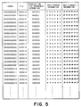
- Fig. 5 is a diagram showing an example of TSAT according to an embodiment of the invention.
- Fig. 6 is a diagram showing GUI images according to a first embodiment of the invention.
- Fig. 7 is a diagram illustrating switching between GUI images according to the first embodiment.
- Fig. 8 is a flow chart illustrating the record operation of the apparatus shown in Fig. 1 according to a second embodiment of the invention.
- Fig. 9 is a diagram showing TSAT according to the second embodiment of the invention.
- Fig. 10 is a diagram showing GUI images according to a third embodiment of the invention.
- Fig. 11 is a diagram illustrating switching between GUI images according to the third embodiment.
- Fig. 12 is a diagram showing GUI images according to a fourth embodiment of the invention.
- Fig. 13 is a diagram illustrating switching between GUI images according to the fourth embodiment.
- Fig. 14 is a flow chart illustrating the record operation according to a fifth embodiment of the invention.
- Fig. 15 which is composed of Figs. 15A and 15B is a flow chart illustrating the record operation according to an embodiment of the invention.
- Fig. 16 is a block diagram of a conventional recording and reproducing apparatus.
-
- Preferred embodiments of the invention will be described with reference to the accompanying drawings.
- In the embodiments to follow, the invention is applied to an apparatus for receiving digital TV broadcasting signals and recording and reproducing them.
- First, data to be used by the embodiments will be described.
- In the embodiments, digital TV signals of video data, audio data and other data are transmitted and received in the form of a transport stream (hereinafter described as TS) of
MPEG 2. The basic data unit is a transport stream packet (hereinafter described as TS packet) having a fixed length of 188 bytes. All data is transmitted by this TS packet, irrespective of the types of data, such as video data, audio data and other data. One TS is generally made of a plurality of programs time divisionally multiplexed. These TSs same in number as the number of transponders transmitting at the same time. - Fig. 2A shows an example of TS packet data of
MPEG 2 in which three programs including video and audio data are encoded and time divisionally multiplexed in accordance with the formats defined in ISO/IEC 13818-1 (system), ISO/IEC 13818-2 (video) and ISO/IEO 13818-3 (audio). - In Fig. 2A, PAT is a program association table, PMT1 is a program map table of a
program number 1, PMT2 is a program map table of aprogram number 2, PMT3 is a program map table of aprogram number 3, TS1-V is video TS packet data of theprogram number 1, TS1-A is audio TS packet data of theprogram number 1, TS2-V is video TS packet data of theprogram number 2, TS2-A is audio TS packet data of theprogram number 2, TS3-V is video TS packet data of theprogram number 3, and TS3-A is audio TS packet data of theprogram number 3. - Of these data, PAT and PMT are data called PSI (Program Specific Information) and are mainly used for simple tuning operation and program selecting operation.
- Each of PAT, PMT and TS packet data has PID (Packet Identification) of 13 bits by which the contents of data can be identified. PAT describes PID of PMT, and PMT describes PID of each of various TS packets such as video, audio and other data of each program contained in TS. An example of PID is shown in Fig. 3.
- Different PID numbers are assigned to video and audio data of the same program. It is defined that PAT is assigned PID = "0000000000000=0X0000". PID of each PMT is designated in a payload of PAT. PID of each of the video and audio packet data is designated by each PMT.
- Fig. 2B shows the structure of TS packet data. Each TS packet has data of 188 bytes including a TS header of top 24 bits, scramble control data of next 2 bits, and the payload such ad video and audio data of remaining bits.
- Data such as video, audio data and other data of TS of
MPEG 2 is transmitted in the unit called a PES (Packetized Elementary Stream) packet. For example, in digital TV broadcasting, video data of 1 GOP of 15 frames from an I picture to the B picture immediately before the next I picture is encoded, and one PES packet is constituted of the encoded video data of 1 GOP. Therefore, the start frame of each PES is always the I picture, i.e., intra-encoded. - Fig. 2C shows three PES packets PES1 to PES3 constituting the video data of the
program number 1. Generally, each of video and image data of one program is divided into a plurality of PES packets. - Each PES packet has a different length, and as shown in Figs. 2C and 2D, one PES packet is divided into a plurality of TS packets which are then transmitted.
- More specifically, in Figs. 2C and 2D, it is shown that a
PES1 packet 201 is divided into a plurality ofTS packets - Each PES packet data has one bit of unit start indicator data (payload_unit_start_indicator in ISO/IEC 13818-1) of the TS packet data IS. This unit start indicator data indicates that a new PES packet starts from the payload of the corresponding TS packet.
- Namely, data of one PES is the data in the payloads of the TS packets from the TS packet having the unit start indicator data "1" to the TS packet immediately before the next TS packet having the unit start indicator data "1". One set of PES packet data is constituted of the payload data of the TS packets including the TS packet having the unit start indicator data "1" and the succeeding n TS packets having the same PID.
- The transmission interval of TS packet data having the same PID and the unit start indicator bit or payload_unit_start_ indicator "1" is determined by television broadcasting institutes in the case of television broadcasting. In this embodiment, for the convenience of description, it is assumed that TS packet data is transmitted at an interval of 5 minutes. If one PES packet is constituted of encoded video data of 1 GOP as described above, the TS packet having the unit start indicator data "1" is essentially transmitted at an interval shorter than 5 minutes.
- An apparatus of receiving such digital TV signals and recording and reproducing them will be described.
- Fig. 1 is a diagram showing a recording and reproducing apparatus according to an embodiment.
- Referring to Fig. 1, a
tuner 101 receives a digital TV signal in accordance with an instruction supplied via a control line 10-15, to output TS data including the program tuned by anoperation unit 135 to anSW circuit 103. TS packet data of time divisionally multiplexed video and audio data of a plurality of programs such as shown in Figs. 2A to 2D is supplied to aTS input line 1. - When TS packet data is received and reproduced in a usual manner, the
SW circuit 103 supplies the TS packet data input via theTS input line 1 to ademultiplexer 105 via aTS data line 2. Thedemultiplexer 105 divides only the TS packet data having the designated PID supplied from asystem control unit 129 via a control line 10-2. - Each TS packet divided by the
demultiplexer 129 is generally transferred as PES packet data defined in ISO/IEC 13818-1. Video packet data is supplied to avideo decoding unit 109 via a videoPES data line 3, and audio PES packet data is supplied via an audioPES data line 4 to anaudio decoding unit 113. - The
video decoding unit 107 is controlled via a control line 10-3 by asystem controller 129, and performs a decoding process ofMPEG 2 for the input video PES packet data to output the decoded video data to avideo control unit 109 via a decodedvideo data line 6. Thevideo control unit 109 is controlled via a control line 10-5 by thesystem controller 129, and converts the decoded video data into a format suitable for adisplay unit 111, e.g., the NTSC format, to output the display video data to thevideo display unit 111 via a displayvideo data line 8. As will be later described, thevideo control unit 109 executes various GUI processes generated by a GUI (Graphical User Interface)composition unit 131 and outputs the results to thedisplay unit 111. - The
audio decoding unit 113 is controlled via a control line 10-4 by thesystem controller 129, and performs a decoding process ofMPEG 2 for the input audio PES packet data to output the decoded audio data to anaudio control unit 115 via a decodedaudio data line 7. Theaudio control unit 115 is controlled via a control line 10-6 by thesystem controller 129, performs a D/A conversion process and the like in order to convert the decoded audio data into a format suitable for an external monitor, and outputs the audio data to anaudio monitor 117 including an amplifier, a speaker and the like via a reproductionaudio data line 9. - Next, the operation of recording received TS packet data so as to allow the data to be randomly accessed, will be described.
- The TS packet data received by the
tuner 101 is input to theSW circuit 103 and to a data control unit 121 via theTS input line 1. The data control unit 121 counts and stores a bit rate of the input TS packet data. - The control process to be executed by the data control unit 121 will be described with reference to the flow chart of Fig. 4.
- Upon a record instruction from the
operation unit 135, thesystem control unit 129 supplies a control signal to the data control unit 121. Upon reception of a record start instruction, the data control unit 121 receives the TS packet data from thetuner 101 at Step S401 (hereinafter Step is omitted), derives PAT from the input TS packet data (S402), and stores it in its inner register. Next, PMT is detected by referring to the stored PAT, and stored in the inner register, and by referring to the stored PMT information, PID of video and audio data of each program is discriminated (S403). Thereafter, the input TS packet data is temporarily latched in amemory 119 made of FIFO (S404). - Next, the data control unit 121 reads the top 24 bits of the TS packet stored in the
memory 119 and latches them in its inner register (namely, 24 bits from the sync byte to PID shown in Fig. 2B are latched)(S405). The lower 13 bits (i.e., PID) of the latched 24 bits are detected which are then compared with PID of the video and audio packet data of each program described in PMT to thereby judge whether the TS packet data is the video TS packet data (S406). If not, it is recorded in adata storage 123 such as a hard disk and a magnetooptical disk (S409). It is then judged whether there is a record end instruction (S410). If not, the top 24 bits of the next TS packet are read and latched (S404). - If the TS packet latched in the
memory 119 is the video TS packet, it is judged from the unit start indicator bit (one bit) at the upper tenth bit whether the TS packet contains the data at the start of the PES packet (S407). If the unit start indicator bit is "0", the TS packet data is stored in the data storage 123 (S409). - If it is judged at S407 that the unit start indicator bit is "1", PID of the TS packet is changed to reproduction time management information to be described later (S408) to thereafter record the TS packet data in the data storage 123 (S409). If the data latched in the
memory 119 is PAT or PMT, it is recorded in thedata storage 123. - As above, the TS packet data shown in Fig. 2A excepting PAT and PMT is recorded in the
data storage 123, with PID of the TS packet data having the unit start indicator bit "1" being changed to the reproduction management information to be described later. PAT and PMT data is recorded in thedata storage 123 in association with the recorded TS packet data. For reproduction, TS packet data read from thedata storage 123 is multiplexed at predetermined timings and output. - The reproduction time management information is selectively assigned a value in conformity with the following five rules.
- (1) A value different from PID = 0X0000 assigned to PAT.
- (2) A value satisfying the condition (1) and being different from PID = 0X0001 assigned to CAT as defined in ISO/IEC 13818-1.
- (3) A value satisfying the conditions (1) and (2) and being different from PID from 0X0002 to 0X000F reserved as defined in ISO/IEC 13818-1.
- (4) A value satisfying the conditions (1) to (3) and being different from PID = 0X1FFF assigned to a "null packet" as defined in ISO/IEC 13818-1.
- (5) A value satisfying the conditions (1) to (4)
and being different from PID contained in TS data input
from the
TS input line 1 shown in Fig. 1 (e.g., a value different from PID from 0X0011 to 0X0019 illustratively shown in Fig. 3). -
- The changed PID and reproduction time management information are input to a TSAT (Transport Stream Accession Table)
composition unit 133 via aTSAT information line 35, as directory information used for random access reproduction. TheTSAT composition unit 133 composes a table (hereinafter called a TSAT) storing the relation between the original PID and changed reproduction time management information and stores TSAT in its inner memory. - An example of TSAT is shown in Fig. 5. TSAT stores: table index information; original PID information of each TS packet at the time when the TS packet is input to the data control unit 121: reproduction time management information replaced by the data control unit 121; management information of the data storage 123 (address information of each TS packet if a semiconductor memory or the like is used, cluster information of each TS packet if a hard disk or the like is used); and management information of a data storage to be described later (address information of sample image data generated by a
GUI composition unit 137 to be described later if a semiconductor memory or the like is used, cluster information of sample image data if a hard disk or the like is used). - The index information is made of, for example, 32 bits. The number of bits is not limited thereto, because it often depends on the system structure, the structure of the data storage and the like, and the random access interval.
- In accordance with the flow chart described above, the received TS packet data is sequentially recorded in the
data storage 123. - Next, the description will be given for GUI which supports random access reproduction for the TS packet data recorded in the
data storage 123. - The data control unit 121 records the received TS packet data in the
data storage 123 as described above and also outputs it to ademultiplexer 125 via adata line 14. - The
demultiplexer 125 detects video data of the video TS packets of theprogram numbers 1 to 3, in accordance with PAT and PMT in the TS packet data input from the data control unit 121, and composes a video PES packet and outputs it to avideo decoding unit 127 via adata line 15. - Upon reception of the video PES packet data of the three programs, the
vide decoding unit 127 starts decoding video data. In this embodiment, only the first video frame (corresponding to I frame of MPEG) of each PES packet data is decoded. Therefore, if twenty sets of PES packet data are generated from the TS packet data having the same PID and recorded in a predetermined period, twenty video frames are decoded. Video data of each decoded frame is used as a sample image used for random access reproduction. - The
vide decoding unit 127 adds reproduction time management information supplied from theTSAT composition unit 133 via aTSAT information line 36, to the data of each decoded video frame (one frame per one PES packet), and outputs the result to theGUI composition unit 131 via a data line 16. - The
GUI composition unit 131 records the video data and reproduction time management information of the first video frame of each PES packet supplied from thevideo decoding unit 127, in thedata storage 137. TheGUI composition unit 131 receives, from the data control unit 121, channel information of each video data input from thevideo decoding unit 127, and records it in association with each video data in adata storage 137. - By using the video data, reproduction management information and channel information recorded in the
data storage 137, GUI images are generated for random access reproduction (search) of the TS packet data recorded in thedata storage 123, as will be described later, and output via adata line 17 to thevideo control unit 109 to be displayed on thevideo display unit 111. - Examples of GUI images generated by the
GUI composition unit 131 and displayed on thedisplay unit 111 are shown in Fig. 6. - In Fig. 6,
reference numeral 601 represents a television channel number selected by theoperation unit 135,reference numeral 602 represents a program recording time, andreference numeral 603 represents a page number of GUI images. - Reference numerals 604-1 to 604-6 represent
sample images 1 to 6 of reduced video frame images decoded by thevideo decoding unit 127 and recorded in thedata storage 137.Reference numeral 605 represents selection buttons for the recorded channel numbers. In this embodiment, since the TS data of three multiplexed channels (programs) are recorded, three channels are displayed.Reference numeral 606 represents a page turn-over button for turning over a display page of GUI images.Reference numeral 607 represents an icon for selecting a candidate image during a GUI operation. A user operates upon theoperation unit 135 including a mouse, a keyboard, various switches for recording, reproducing and other operations, to thereby instruct random reproduction to be described later. - An example of switching between GUI images when a GUI selection operation is effected by the
icon 607 is shown in Fig. 7. - Referring to Fig. 7, an arrow (1) shows a selection of an image 2 (604-2) by the
icon 607 shown in Fig. 6. In this operation shown by the arrow (1), original image data of the reducedGUI image 2 is read from thedata storage 137 shown in Fig. 1 and displayed on thedisplay unit 111, or program reproduction of the TS packet data recorded in thedata storage 123 starts from an area corresponding to theimage 2, i.e., the random access reproduction starts. The operation of the random access reproduction will be later described. - In Fig. 7, the operation shown by an arrow (2) illustrates a switch to the GUI images at
page 2/3 of the same channel number (e.g., 204 ch) by designating the page turn-over switch 206 with theicon 207. The operation shown by an arrow (3) illustrates a switch to GUI images, for example, at 198 ch by designating the channelnumber selection button 205 with theicon 207. With the operation shown by the arrow (3), each sample image displayed is the image at 198 ch. - Next, the operation of a random access by using GUI images will be described.
- When an instruction of random access reproduction is issued from the
operation unit 135, thesystem control unit 129 controls theGUI composition unit 131 to generate GUI images such as shown in Fig. 6 and display them on thedisplay unit 111. - The random access reproduction of, for example, the
image 2 shown in Fig. 6 is performed in the following manner. In response to an instruction from theoperation unit 135, thesystem control unit 129 instructs theGUI composition unit 131 to send the reproduction time management information of the designatedimage 2. TheGUI composition unit 131 reads the reproduction time management information recorded in thedata storage 137 together with the video data of theimage 2, and outputs it to thesystem control unit 129. In accordance with the supplied reproduction management information (herein assumed to be 0X0024), thesystem control unit 129 acquires the index information (0X00000004 shown in Fig. 5) of TSAT by referring to TSAT stored in the inner memory of theTSAT composition unit 133 via theTSAT information line 37. - In accordance with the acquired index information, PID originally affixed to the TS packet containing the data of the selected
image 2 and the management information of thedata storage 123 shown in Fig. 1 is obtained. In accordance with this management information, the TS packet data recorded in thedata storage 123 is reproduced and temporarily stored in thememory 119. - The data control unit 121 refers to TSAT, and if PID of the TS packet stored in the
memory 119 was changed to the reproduction management information when the TS packet was recorded, the data control unit 121 changes the reproduction time management information to the original PID. PAT and PMT reproduced from thedata storage 123 and stored in the inner register are added to the reproduced TS packet to reconfigure the TS packet data time divisionally multiplexed as shown in Fig. 2A. The TS packet data is then input to theSW circuit 103 via thedata line 11 shown in Fig. 1 at the bit rate corresponding to the recording bit rate stored in the data control unit 121. When the data control unit 121 reproduces TS packet data from thedata storage 123, PAT and PMT are always added in this order to the start of the TS packet data train and output to theSW circuit 103, irrespective of whether the reproduction is normal reproduction or random reproduction. Thereafter, PAT and PMT are inserted by predetermined timings. - For the reproduction, the
SW circuit 103 selects the reproduced TS packet data from thesignal line 11 and outputs it to thedemultiplexer 105. Thereafter, the processes similar to those during reception are performed to display the reproduced image on thedisplay unit 111 and output reproduced sounds from theaudio monitor 117. - If the normal reproduction is to be performed instead of the random access reproduction, the
system control unit 129 refers to TSAT to detect the storage location of the start TS packet of the designated program in thedata storage 123, and controls the data control unit 121 to start the reproduction of the TS packet data from the storage location. The processes to follow are similar to those of the random access reproduction. - In this embodiment, when the TS packet data is recorded in the data storage, PID (Program ID) of the video TS packet data having the payload_unit_start_ indicator "1", i.e., of the TS packet containing the start portion of each PES packet, is changed to the reproduction time management information having the same number of bits, and the storage location of the changed PID is stored in TSAT. Therefore, the random access reproduction from the start portion of each PES packet can be executed on the PES packet basis.
- Furthermore, since GUI images are displayed to support the random access reproduction by using the frame image in the start portion of each PES packet, the reproduction (random access reproduction) from a position desired by a user can be easily realized.
- In this embodiment, a TS packet containing the start portion of the PES packet is detected and PID of this TS packet is changed to the reproduction management information shown in Fig. 5. Instead, PID of the received TS packet data may not be changed and may be directly recorded in the data storage. In this case, TSAT is formed by adding an index to the storage location of the TS packet containing the start portion of PES, and this index is used as the directory for the random access reproduction.
- The recording operation of the data control unit 121 to realize this will be described with reference to the flow chart of Fig. 8.
- Fig. 8 is a flow chart illustrating the recording operation of the data control unit 121 according to the second embodiment.
- Referring to Fig. 8, upon a record instruction from the
operation unit 135, thesystem control unit 129 supplies a control signal to the data control unit 121. Upon reception of a record start instruction, the data control unit 121 receives the TS packet data from thetuner 101 at S801, derives PAT from the input TS packet data (S802), and stores it in its inner register. Next, PMT is detected by referring to the stored PAT, and stored in the inner register, and by referring to the stored PMT information, PID of video and audio data of each program is discriminated (S803). Thereafter, the input TS packet data is temporarily latched in thememory 119 made of FIFO (S804). - Next, the data control unit 121 reads the top 24 bits of the TS packet stored in the
memory 119 and latches them in its inner register. The lower 13 bits of the latched 24 bits are detected which are then compared with PID of the video and audio packet data of each program described in PMT to thereby judge whether the TS packet data is the video TS packet data (S806). If not, it is recorded in thedata storage 123 such as a hard disk and a magnetooptical disk (S808). It is then judged whether there is a record end instruction (S811). If not, the top 24 bits of the next TS packet are read and latched (S804). - If the TS packet latched in the
memory 119 is the video TS packet, it is judged from the unit start indicator bit at the upper tenth bit whether the TS packet contains the data at the start of the PES packet (S807). If the unit start indicator bit is "0", the TS packet data is stored in the data storage 123 (S808). - If it is judged at S807 that the unit start indicator bit is "1", the TS packet is recorded in the data storage 123 (S809), an index is affixed to this TS packet, and the storage location information of the TS packet is output to the TSAT composition unit 133 (S810). Similar processes are repeated so that the storage locations, in the
data storage 123, of the video TS packets containing the start portion of PES are output to theTSAT composition unit 133 together with the index numbers. - In the second embodiment, the
TSAT composition unit 133 generates TSAT such as shown in Fig. 9 and stores it in the inner memory. TSAT shown in Fig. 9 stores in its inner memory the storage location, in thedata storage 123, of the TS packet containing the start portion of PES as well as the index data in association with the storage location. TSAT also stores the associated storage location of the sample image data recorded in thedata storage 137 by theGUI composition unit 131. - The data control unit 121 outputs the received TS packet data to the
demultiplexer 125. Thedemultiplexer 125 detects the video TS packet from the input TS packet data, generates the video PES packet data for each program, and outputs it to thevideo decoding unit 127. - The
video decoding unit 127 decodes video data of only one frame in the start portion of each PES among the input video PES data. Thevideo decoding unit 127 reads from theTSAT composition unit 133 the index number data corresponding to the image data of each decoded frame, i.e., index number data affixed to the TS packet containing the video data of the decoded frame, and adds the index number data to the decoded vide data to output the result to theGUI composition unit 131. - The
GUI composition unit 131 records in thedata storage 137 the decoded video data and index number data output from thevideo decoding unit 127 as well as the channel information of each video data received from the data control unit 121, each data being associated with each other. By using the recorded decoded video data and index number data and channel information, theGUI composition unit 131 generates GUI images as shown in Fig. 6 and outputs them to thevideo control unit 109. - Next, the operation of random access reproduction by using GUI images according to the second embodiment will be described.
- When an instruction of random access reproduction is issued from the
operation unit 135, thesystem control unit 129 controls theGUI composition unit 131 to generate GUI images such as shown in Fig. 6 and display them on thedisplay unit 111. - The random access reproduction of, for example, the
image 2 shown in Fig. 6 is performed in the following manner. In response to an instruction from theoperation unit 135, thesystem control unit 129 shown in Fig. 1 instructs theGUI composition unit 131 to send the index number data of the designatedimage 2. TheGUI composition unit 131 reads the index number data recorded in thedata storage 137 together with the video data of theimage 2, and outputs it to thesystem control unit 129. - In accordance with the supplied index number data, the
system control unit 129 acquires the data storage management information of the TS packet containing the data of the selectedimage 2, by referring to TSAT stored in the inner memory of theTSAT composition unit 133 via theTSAT information line 37. In accordance with the acquired data storage management information, the TS packet data is reproduced from thedata storage 123 and temporarily stored in thememory 119. - The data control unit 121 adds PAT and PMT reproduced from the
data storage 123 and stored in the inner register to the reproduced TS packet to reconfigure the TS packet data time divisionally multiplexed as shown in Fig. 2A. The TS packet data is then input to theSW circuit 103 via thedata line 11 shown in Fig. 1 at the bit rate corresponding to the recording bit rate stored in the data control unit 121. When the data control unit 121 reproduces TS packet data from thedata storage 123, PAT and PMT are always added in this order to the start of the TS packet data train and output to theSW circuit 103, irrespective of whether the reproduction is normal reproduction or random reproduction. Thereafter, PAT and PMT are inserted by predetermined timings. - For the reproduction, the
SW circuit 103 selects the reproduced TS packet data from thesignal line 11 and outputs it to thedemultiplexer 105. Thereafter, the processes similar to those during reception are performed to display the reproduced image on thedisplay unit 111 and output reproduced sounds from theaudio monitor 117. - If the normal reproduction is to be performed instead of the random access reproduction, the
system control unit 129 refers to TSAT to detect the storage location of the start TS packet of the designated program in thedata storage 123, and controls the data control unit 121 to start the reproduction of the TS packet data from the storage location. The processes to follow are similar to those of the random access reproduction. - In this embodiment, when the TS packet data is recorded in the data storage, an index number is affixed to the video TS packet data having the unit start indicator bit "1". A directory is formed by using the storage location of the TS packet and stored in TSAT. Therefore, the random access reproduction from the start portion of each PES packet can be executed in the PES packet unit.
- Furthermore, since GUI images are displayed to support the random access reproduction by using the frame image in the start portion of each PES packet, the reproduction from a position desired by a user can be easily realized.
- Next, the third embodiment of the invention will be described.
- Also in the third embodiment, the structure and operation of the recording and reproducing apparatus are similar to those described with Fig. 1. In the third embodiment, GUI images used for random access reproduction are different from those of the first and second embodiments. GUI images of the third embodiment are shown in Fig. 10.
- In Fig. 10,
reference numeral 1001 represents a selected television channel number,reference numeral 1003 represents a program recording time, andreference numeral 1005 represents a page number of GUI images. - Reference numerals 1007-1 to 1007-5 represent
sample images 1 to 5 of reduced video frame images decoded by thevideo decoding unit 127.Reference numeral 1009 represents selection buttons for the recorded channel numbers.Reference numeral 1011 represents a page turn-over button for turning over a display page of GUI images.Reference numeral 1013 represents an icon for selecting a candidate image during a GUI operation.Reference numeral 1015 represents a switching button for selecting an image to be displayed at the start of random access reproduction. - An example of switching between GUI images when a GUI selection operation is effected by the
icon 1013 is shown in Fig. 11. - Referring to Fig. 11, an arrow (1) shows a selection of an
image 3 by theicon 1013. In this operation shown by the arrow (1), original image data of the reducedGUI image 3 is read from thedata storage 137 shown in Fig. 1 and displayed, or program reproduction of the TS packet data recorded in thedata storage 123 starts from an area corresponding to theimage 3 in the TS packet data, i.e., the random access reproduction starts, to thereby display the image on thedisplay unit 111 as indicated by 1103. - The operation shown by an arrow (2) illustrates a switch to a
GUI image 13 which is selected as the candidate image at the start of the random access by designating the page turn-over switch 1011 with theicon 1013 as indicated by 1105. The operation shown by an arrow (3) illustrates a switch to GUI images at 198 ch by designating the channelnumber selection button 1009 with theicon 1013, as indicated by 1107. - Next, the fourth embodiment of the invention will be described.
- Also in the fourth embodiment, the structure and operation of the recording and reproducing apparatus are similar to those described with Fig. 1. In the fourth embodiment, GUI images used for random access reproduction are different from those of the first to third embodiments. GUI images of the fourth embodiment are shown in Fig. 12.
- In Fig. 12,
reference numeral 1201 represents a selected television channel number, andreference numeral 1203 represents a program recording time. - Reference numeral 1205-1 represents a
sample image 2 of a reduced video frame image decoded by thevideo decoding unit 127.Reference numeral 1207 represents selection buttons for the recorded channel numbers.Reference numeral 1209 represents a page turn-over button for turning over a display page of GUI images to select the sample image for the start of random access reproduction.Reference numeral 1211 represents an icon for selecting a candidate image during a GUI operation. - An example of switching between GUI images when a GUI selection operation is effected by the
icon 1211 is shown in Fig. 13. - Referring to Fig. 13, an arrow (1) shows a selection of an
image 2 by theicon 1211. In this operation shown by the arrow (1), original image data of the reducedGUI image 2 is read from thedata storage 137 shown in Fig. 1 and displayed, or program reproduction of the TS packet data recorded in thedata storage 123 starts from an area corresponding to theimage 2 in the TS packet data, i.e., the random access reproduction starts, to thereby display the image on thedisplay unit 111 as indicated by 1303. - The operation shown by an arrow (2) illustrates a switch to a
GUI image 3 which is selected as the candidate image at the start of the random access by designating the page turn-over switch 1209 with theicon 1211 as indicated by 1305. The operation shown by an arrow (3) illustrates a switch to a GUI image at 198 ch for example by designating the channelnumber selection button 1207 with theicon 1211, as indicated by 1307. - Next, the fifth embodiment of the invention will be described.
- In the first and second embodiments, all TS packets containing the start portion of each video PES packet are detected from the received TS packet data, and an index is added to the storage location of the detected TS packet to form a directory which is stored in TSAT. The index number may be affixed to the TS packet each time n (n is an integer of 2 or larger) TS packets containing the start portion of the PES packet are detected. The storage location of this TS packet affixed with the index number is stored in TSAT. In this manner, the time interval of random access can be changed.
- The operation of TS packet recording and TSAT generation by the
data control unit 129 according to the fifth embodiment will be described with reference to the flow chart shown in Fig. 14. - In this embodiment, the recording operation by the
data control unit 127 is changed as illustrated in Fig. 14 to change the time interval of random access start candidate images. More specifically, in the first and second embodiments, the time interval of random access start candidate images is set to 5 minutes as illustrated in Fig. 6, it can be changed to 10 minutes according to the flow chart shown in Fig. 14. - Upon a record instruction from the
operation unit 135, thesystem control unit 129 supplies a control signal to the data control unit 121. Upon reception of a record start instruction, the data control unit 121 first resets a variable c to 0 (S1401), the variable being used for counting the number of detections of the TS packet having the unit start indicator bit "1", and receives at S1402 the TS packet data from thetuner 101. In this embodiment, since the TS packet data multiplexing three programs shown in Fig. 2A is recorded, three variables c1, c2 and c3 corresponding to three programs are prepared. Since the processes for the TS packet data of each program are the same, processes for one program only will be described in the following. - After the TS packet is received at S1401, the data control unit 121 detects PAT from the input TS packet data (S1402), and stores it in its inner register. Next, PMT is detected by referring to the stored PAT, and stored in the inner register, and by referring to the stored PMT information, PID of video and audio data of each program is discriminated (S1403). Thereafter, the input TS packet data is temporarily latched in a
memory 119 made of FIFO (S1404). - Next, the data control unit 121 reads the top 24 bits of the TS packet stored in the
memory 119 and latches them in its inner register (S1405). The lower 13 bits of the latched 24 bits are detected which are then compared with PID of the video and audio packet data of each program described in PMT to thereby judge whether the TS packet data is the video TS packet data (S1406). If not, it is recorded in adata storage 123 such as a hard disk and a magnetooptical disk (S1411). It is then judged whether there is a record end instruction (S1412). If not, the top 24 bits of the next TS packet are read and latched (S1404). - If the TS packet latched in the
memory 119 is the video TS packet, it is judged from the unit start indicator bit at the upper tenth bit whether the TS packet contains the data at the start of the PES packet (S1407). If the unit start indicator bit is "0", the TS packet data is stored in the data storage 123 (S1411). - If it is judged at S1407 that the unit start indicator bit is "1", it is judged whether the variable c is 0 (S1408). If the variable c is 0, PID of the TS packet is changed to the reproduction time management information (S1410) to increment the variable c by 1 and thereafter record the TS packet data in the data storage 123 (S1411). If the variable c is not 0 at S1408, it is judged that although the TS packet contains the data at the start of PES, the TS packet data is not a random access start candidate and the PID of the TS packet is not changed.
- If the variable c is not 0 at S1408 and if the variable c is n-1 (S1413), the variable c is reset to 0 and the TS packet is recorded in the data storage 123 (S1411). If the variable c is not n-1, the variable c is incremented by 1, and the TS packet is recorded in the data storage 123 (S1415).
- In this embodiment, the data control unit 121 operates in accordance with the flow chart of Fig. 14 at n = 2. Each time the TS packet having the unit start indicator bit "1" is detected twice, PID of the detected TS packet data is changed and stored in the
data storage 123 shown in Fig. 1. In this manner, the time interval of 5 minutes for random access start candidate images in the first and second embodiments can be doubled and set to 10 minutes. - The random access reproduction and ordinary reproduction of TS packet data of the fifth embodiment are similar to those of the first to fourth embodiments excepting that the time interval of random access start images is prolonged.
- In this embodiment, the data control unit 121 operates in accordance with the flow chart of Fig. 14 at n = 2, and each time the TS packet having the unit start indicator bit "1" is detected twice, PID is changed. Instead, n may be set to 3 or 4 to change the time when PID is changed to the reproduction time management information. The time interval of random access start candidate images can therefore be set to a threefold of 15 minutes and a fourfold of 20 minutes as desired.
- Also in this embodiment, although the data control unit 121 stores in advance the value n. Instead, a user may set the value n from the
operation unit 135. - In this embodiment, when the TS packet data is recorded in the data storage, each time the TS packet having the payload_unit_start_indicator "1", i.e., the TS packet containing the start portion of each PES packet is detected n times, PID (Program ID) of 13 bits of the TS packet is changed to the reproduction time management information having the same number of bits, and the storage location of the changed PID is stored in TSAT. Therefore, the random access reproduction from the start portion of each PES packet can be executed in the unit of n PES packets.
- Furthermore, since GUI images are displayed to support the random access reproduction by using the frame image in the start portion of each PES packet, the reproduction (random access reproduction) from a position desired by a user can be easily realized.
- In this embodiment, a TS packet containing the start portion of the PES packet is detected and PID of this TS packet is changed to the reproduction time management information shown in Fig. 5. Instead, similar to the second embodiment, PID of the received TS packet data may not be changed and may be directly recorded in the data storage. In this case, TSAT is formed by adding an index to the storage location of the TS packet containing the start portion of PES, and this index is used as the directory for the random access reproduction. The recording operation of the data control unit 121 to realize this will be described with reference to the flow chart of Figs. 15A and 15B.
- Referring to Figs. 15A and 15B, upon a record instruction from the
operation unit 135, thesystem control unit 129 supplies a control signal to the data control unit 121. Upon reception of a record start instruction, the data control unit 121 first resets a variable c to 0 (S1501), the variable c being used for counting the number of detections of the TS packet having the unit start indicator bit "1", and then receives the TS packet data from thetuner 101. - After the TS packet data is received at S1501, the data control unit 121 detects PAT from the input TS packet data (S1502), and stores it in its inner register. Next, PMT is detected by referring to the stored PAT, and stored in the inner register, and by referring to the stored PMT information, PID of video and audio data of each program is discriminated (S1503). Thereafter, the input TS packet data is temporarily latched in the
memory 119 made of FIFO (S1504). - Next, the data control unit 121 reads the top 24 bits of the TS packet stored in the
memory 119 and latches them in its inner register (S1505). The lower 13 bits of the latched 24 bits are detected which are then compared with PID of the video and audio packet data of each program described in PMT to thereby judge whether the TS packet data is the video TS packet data (S1506). If not, it is recorded in thedata storage 123 such as a hard disk and a mnagnetooptical disk (S1507). It is then judged whether there is a record end instruction (S1508). If not, the top 24 bits of the next TS packet are read and latched (S1504). - If the TS packet latched in the
memory 119 is the video TS packet at S1506, it is judged from the unit start indicator bit at the upper tenth bit whether the TS packet contains the data at the start of the PES packet (S1509). If the unit start indicator bit is "0", the TS packet data is stored in the data storage 123 (S1507). - If it is judged at S1509 that the unit start indicator bit is "1", it is judged whether the variable c is 0 (S1408). If the variable c = 0, the TS packet is recorded in the
data storage 123, an index is affixed to the TS packet, the storage location information of the TS packet is output to the TSAT composition unit 133 (S1515). The variable c is then incremented by 1 to return to S1508 (S1516). - If the variable c is not 0 at S1510, it is judged although the TS packet contains the data at the start portion of PES, it is not a random access start candidate, and PID is not changed.
- If the variable c is not 0 at S1510 and if the variable c is n-1 (S1511), the variable c is reset to 0 and the TS packet is recorded in the data storage 123 (S1512). If the variable c is not n-1, the variable c is incremented by 1, and the TS packet is recorded in the data storage 123 (S1513).
- In this embodiment, the data control unit 121 operates in accordance with the flow chart of Figs. 15A and 15B at n = 2. Each time the TS packet having the unit start indicator bit "1" is detected twice, PID of the detected TS packet data is changed and stored in the
data storage 123 shown in Fig. 1. In this manner, the time interval of 5 minutes for random access start candidate images in the embodiments shown in Fig. 4 can be doubled and set to 10 minutes. - The random access reproduction and ordinary reproduction of TS packet data of the fifth embodiment are similar to those of the first to fourth embodiments excepting that the time interval of random access start images is prolonged.
- In this embodiment, the data control unit 121 operates in accordance with the flow chart of Figs. 15A and 15B at n = 2, and each time the TS packet having the unit start indicator bit "1" is detected twice, PID is changed. Instead, n may be set to 3 or 4 to change the time when PID is changed to the reproduction time management information. The time interval of random access start candidate images can therefore be set to a threefold of 15 minutes and a fourfold of 20 minutes as desired.
- Also in this embodiment, although the data control unit 121 stores in advance the value n. Instead, a user may set the value n from the
operation unit 135. - In this embodiment, when the TS packet data is recorded in the data storage, each time the TS packet having the payload_unit_start_indicator "1" , i.e., the TS packet containing the start portion of each PES packet is detected n times, an index number is affixed to the video TS packet data, and the storage location of the TS packet as well as the index number is stored in TSAT. Therefore, the random access reproduction from the start portion of each PES packet can be executed in the unit of n PES packets.
- Furthermore, since GUI images are displayed to support the random access reproduction by using the frame image in the start portion of each PES packet, the reproduction (random access reproduction) from a position desired by a user can be easily realized.
- In the above embodiments, the present invention is applied to an apparatus for receiving digital TV broadcasting and recording and reproducing it. The invention can easily be applied to other apparatus for receiving, recording and reproducing a data train multiplexing a plurality of programs each constituted of a plurality of packets such as TS of
MPEG 2, with similar expected advantages. - Next, a storage medium according to another embodiment of the invention will be described.
- The system shown in Fig. 1 may be realized by hardware or by a computer system having a CPU and a memory. If the system is to be realized by a computer system, the memory constitutes the storage medium of the invention. This storage medium stores therein a program which executes a process for controlling the above-described operations in accordance with the flow charts shown in Figs. 4, 8, 14 and 15 and the like of the above embodiments.
- The storage medium may be: semiconductor memories such as a ROM and a RAM; an optical disk; a magnetooptical disk; and a magnetic storage medium which may be realized by a CD-ROM, a floppy disk, a magnetic tape, a magnetic card, a nonvolatile memory card or the like.
- The object of the invention can be achieved with similar advantages by supplying the system shown in Fig. 1, another system or an apparatus with the storage medium storing software program codes realizing the functions of each embodiment described above, and by reading and executing the programs codes stored in the storage medium by the system or computer.
- Also the object of the invention can be achieved with similar advantages, by realizing the functions of each embodiment by executing a portion or the whole of processes by an OS or the like running on a computer, or by realizing the functions of each embodiment by writing the program codes read from the storage medium into a memory of a function expansion board inserted into a computer or of a function expansion unit connected to the computer, and thereafter by executing a portion or the whole of actual processes by a CPU or the like of the function expansion board or function expansion unit.
- Many widely different embodiments of the present invention may be constructed without departing from the spirit and scope of the present invention. It should be understood that the present invention is not limited to the specific embodiments described in the specification, except as defined in the appended claims.
Claims (38)
- A recording apparatus comprising:receiving means for receiving a data train multiplexing a plurality of programs each having a plurality of transmission packets;recording means for recording the received data train in a recording medium; andgenerating means for generating a recording location table of recording location data as to a recording location of a predetermined transmission packet in the storage medium among a plurality of transmission packets of each program in the data train.
- An apparatus according to claim 1, wherein data of each of the plurality of programs includes a plurality of data packets, and each of the plurality of transmission packets includes one of a plurality of portions obtained by dividing each of the plurality of data packets of the plurality of programs.
- An apparatus according to claim 2, wherein the predetermined transmission packet includes a packet having a start portion of the data packet.
- An apparatus according to claim 1, wherein each of the plurality of transmission packets has ID data, and said generating means detects the ID data from the data train and generates the recording location table by using detection results of the ID data.
- An apparatus according to claim 4, wherein each of the plurality of transmission packets has indicator data indicating that the transmission packet is the predetermined transmission packet, and wherein said generating means generates the recording location table on the basis of a result of ID data detection and the indication data of the plurality of transmission packets.
- An apparatus according to claim 4, wherein the ID data has a different value for each of the plurality of programs, and the data train further comprises a program map table describing the value of the ID data of each program.
- An apparatus according to claim 6, wherein the data train further comprises a program association table describing the value of the ID data of the program map table, and the ID data of the program association table has a predetermined value.
- An apparatus according to claim 4, wherein said recording means changes the ID data of the predetermined transmission packet to reproduction management information and stores the reproduction management information in the recording medium, and said generating means generates the recording location table in accordance with the recording location data and the reproduction management information.
- An apparatus according to claim 1, wherein the plurality of transmission packets have image data of each program.
- An apparatus according to claim 9, further comprising:search image generating means for generating search image data by using image data of the predetermined transmission packet; andstoring means for storing the search image data.
- An apparatus according to claim 9, further comprising:separating means for separating the transmission packet of a designated program from the data train;decoding means for decoding image data of the transmission packet of the designated program separated by said separating means; andoutputting means for outputting the decoded image data to a display unit which displays an image of the image data output from said outputting means.
- An apparatus according to claim 11, further comprising:reproducing means for reproducing the data train from the storage medium by using the recording location table; andselecting means for selecting either the data train received by said receiving means or the data train reproduced by said reproducing means and outputting the selected data train to said separating means.
- An apparatus for recording a data train multiplexing a plurality of programs each having a plurality of transmission packets, data of each of the plurality of programs including a plurality of data packets, and each of the plurality of transmission packets including one of a plurality of portions obtained by dividing each of the plurality of data packets of the plurality of programs, the apparatus comprising:generating means for generating control data for reproducing the data train in a unit of n (n being an integer of 1 or larger) data packets; andstoring means for storing the control data.
- An apparatus according to claim 13, wherein said generating means detects a transmission packet containing a start portion of the data packet from the data train and generates the control data by using a detection result.
- An apparatus according to claim 14, wherein the control data includes recording location data in a storage medium of the transmission packet containing the start portion of the data packet.
- An apparatus according to claim 13, wherein the data train includes image data.
- An apparatus according to claim 16, further comprising search image generating means for generating search image data by using the image data of the data packet, wherein said storing means stores the search image data.
- An apparatus according to claim 17, further comprising:displaying means for displaying a plurality screen of images of the search image data stored in said storing means;designating means for manually designating a desired screen from the plurality screen of images displayed on said displaying means; andreproducing means for reproducing the data train in accordance with a screen designated by said designating means and the control data stored in said storing means.
- An apparatus according to claim 16, wherein the image data is encoded through intra-picture encoding and inter-picture encoding, and wherein a head frame of image data of the plurality of data packets is encoded through the intra-picture encoding.
- An apparatus for receiving a television signal multiplexing a plurality of programs each having a plurality of transmission packets and recording the television signal in a storage medium, data of each of the plurality of programs including a plurality of data packets, and each of the plurality of transmission packets including one of a plurality of portions obtained by dividing each of the plurality of data packets of the plurality of programs, the apparatus comprising:generating means for generating control data for reproducing the data train recorded in the storage medium from a desired locatio of one program, by using the received television signal; andstoring means for storing the control data.
- A television signal receiving apparatus comprising:receiving means for receiving a television signal arranged in a transport stream format of MPEG 1, one transport stream containing data of a plurality of programs;recording means for recording the received television signal in a storage medium in a state of the transport stream;generating means for generating control data for reproducing the television signal recorded in the storage medium in the state of the transport stream from a desired location of each program, by using the received television signal; andstoring means for storing the control data.
- A recording apparatus comprising:receiving means for receiving a data train multiplexing a plurality of programs each having a plurality of transmission packets, each of the plurality of transmission packets including data of each program and ID data representative of a type of data contained in the transmission packet; andrecording means for recording the received data train in a storage medium, said recording means changing the ID data of a predetermined transmission packet among the plurality of transmission packets of one program in the data train, to reproduction management information and storing the reproduction management information.
- An apparatus according to claim 27, further comprising generating means for generating a control table storing the reproduction management information and the ID data before being changed to the reproduction management information, and storing the control table in said storing means.
- A recording method comprising:a receiving step of receiving a data train multiplexing a plurality of programs each having a plurality of transmission packets;a recording step of recording the received data train in a recording medium; anda generating step of generating a recording location table of recording location data as to a recording location of a predetermined transmission packet in the storage medium among a plurality of transmission packets of each program in the data train.
- A method according to claim 24, wherein data of each of the plurality of programs includes a plurality of data packets, and each of the plurality of transmission packets includes one of a plurality of portions obtained by dividing each of the plurality of data packets of the plurality of programs.
- A method according to claim 25, wherein the predetermined transmission packet includes a packet having a start portion of the data packet.
- A method according to claim 24, wherein each of the plurality of transmission packets has ID data, and said generating step detects the ID data from the data train and generates the recording location table by using detection results of the ID data.
- A method according to claim 27, wherein each of the plurality of transmission packets has indicator data indicating that the transmission packet is the predetermined transmission packet, and wherein said generating step includes a step of generating the recording location table on the basis of a result of ID data detection and the indication data of the plurality of transmission packets.
- A method according to claim 27, wherein the ID data has a different value for each of the plurality of programs, and the data train further comprises a program map table describing the value of the ID data of each program.
- A method according to claim 29, wherein the data train further comprises a program association table describing the value of the ID data of the program map table, and the ID data of the program association table has a predetermined value.
- A method of recording a data train multiplexing a plurality of programs each having a plurality of transmission packets, data of each of the plurality of programs including a plurality of data packets, and each of the plurality of transmission packets including one of a plurality of portions obtained by dividing each of the plurality of data packets of the plurality of programs, the method comprising:a generating step of generating control data for reproducing the data train in a unit of n (n being an integer of 1 or larger) data packets; anda storing step of storing the control data.
- A method according to claim 31, wherein said generating step detects a transmission packet containing a start portion of the data packet from the data train and generates the control data by using a detection result.
- A method according to claim 32, wherein the control data includes recording location data in a storage medium of the transmission packet containing the start portion of the data packet.
- A method according to claim 31, wherein the data train includes image data.
- A method according to claim 32, wherein the image data is encoded through intra-picture encoding and inter-picture encoding, and wherein a head frame of image data of the plurality of data packets is encoded through the intra-picture encoding.
- A method of receiving a television signal multiplexing a plurality of programs each having a plurality of transmission packets and recording the television signal in a storage medium, data of each of the plurality of programs including a plurality of data packets, and each of the plurality of transmission packets including one of a plurality of portions obtained by dividing each of the plurality of data packets of the plurality of programs, the method comprising:a generating step of generating control data for reproducing the data train recorded in the storage medium from a desired locatio of one program, by using the received television signal; anda storing step of storing the control data.
- A television signal receiving method comprising:a receiving step of receiving a television signal arranged in a transport stream format of MPEG 1, one transport stream containing data of a plurality of programs;a recording step of recording the received television signal in a storage medium in a state of the transport stream;a generating step of generating control data for reproducing the television signal recorded in the storage medium in the state of the transport stream from a desired location of each program, by using the received television signal; anda storing step of storing the control data.
- A recording method comprising:a receiving step of receiving a data train multiplexing a plurality of programs each having a plurality of transmission packets, each of the plurality of transmission packets including data of each program and ID data representative of a type of data contained in the transmission packet; anda recording step of recording the received data train in a storage medium, said recording setp changing the ID data of a predetermined transmission packet among the plurality of transmission packets of one program in the data train, to reproduction management information and storing the reproduction management information.
Applications Claiming Priority (4)
| Application Number | Priority Date | Filing Date | Title |
|---|---|---|---|
| JP4550699 | 1999-02-23 | ||
| JP4550699 | 1999-02-23 | ||
| JP2000044571 | 2000-02-22 | ||
| JP2000044571A JP2000312342A (en) | 1999-02-23 | 2000-02-22 | Recording and reproducing device, method therefor, recorder, method therefor and computer-readable storage medium |
Publications (2)
| Publication Number | Publication Date |
|---|---|
| EP1033875A2 true EP1033875A2 (en) | 2000-09-06 |
| EP1033875A3 EP1033875A3 (en) | 2006-01-25 |
Family
ID=26385514
Family Applications (1)
| Application Number | Title | Priority Date | Filing Date |
|---|---|---|---|
| EP00301377A Withdrawn EP1033875A3 (en) | 1999-02-23 | 2000-02-22 | Recording and reproducing apparatus |
Country Status (4)
| Country | Link |
|---|---|
| US (1) | US7142777B1 (en) |
| EP (1) | EP1033875A3 (en) |
| JP (1) | JP2000312342A (en) |
| CN (1) | CN1270525C (en) |
Cited By (3)
| Publication number | Priority date | Publication date | Assignee | Title |
|---|---|---|---|---|
| EP1340227A1 (en) * | 2000-11-22 | 2003-09-03 | Lg Electronics Inc. | Method for providing program specific information recorded on high density disc medium |
| WO2006114761A1 (en) * | 2005-04-26 | 2006-11-02 | Koninklijke Philips Electronics N.V. | A device for and a method of detecting positions of intra-coded frames in a data stream |
| US7693399B2 (en) | 2002-07-11 | 2010-04-06 | Lg Electronics Inc. | Method for providing program specific information recorded on high density disc medium |
Families Citing this family (21)
| Publication number | Priority date | Publication date | Assignee | Title |
|---|---|---|---|---|
| CN1652239B (en) * | 2000-11-22 | 2013-03-20 | Lg电子株式会社 | Method for providing special information of program recorded on high-density CD medium |
| JP3992979B2 (en) * | 2001-12-28 | 2007-10-17 | パイオニア株式会社 | Information recording medium, information recording apparatus and method, information reproducing apparatus and method, information recording / reproducing apparatus and method, computer program for recording or reproduction control, and data structure including control signal |
| JP2003199048A (en) * | 2001-12-28 | 2003-07-11 | Pioneer Electronic Corp | Information recording medium, apparatus and method, information reproducing apparatus and method, information recording/reproducing apparatus and method, computer program for control of recording or reproducing, and data structure including control signal |
| JP2003199049A (en) * | 2001-12-28 | 2003-07-11 | Pioneer Electronic Corp | Information recording medium, apparatus and method, information reproducing apparatus and method, information recording/reproducing apparatus and method, computer program for control of recording or reproducing, and data structure including control signal |
| JP2003199047A (en) * | 2001-12-28 | 2003-07-11 | Pioneer Electronic Corp | Information recording medium, apparatus and method, information reproducing apparatus and method, information recording/reproducing apparatus and method, computer program for control of recording or reproducing, and data structure including control signal |
| JP3948979B2 (en) | 2002-02-18 | 2007-07-25 | パイオニア株式会社 | Information recording medium, information recording apparatus and method, information reproducing apparatus and method, information recording / reproducing apparatus and method, computer program for recording or reproduction control, and data structure including control signal |
| JP3954406B2 (en) * | 2002-02-18 | 2007-08-08 | パイオニア株式会社 | Information recording medium, information recording apparatus and method, information reproducing apparatus and method, information recording / reproducing apparatus and method, computer program for recording or reproduction control, and data structure including control signal |
| JP2003304497A (en) * | 2002-04-08 | 2003-10-24 | Pioneer Electronic Corp | Information recording medium, information recording apparatus and method thereof, information reproducing apparatus and method thereof, information recording and reproducing apparatus and method thereof, computer program for controlling record and reproduction, and data structure containing control signal |
| JP2003304498A (en) * | 2002-04-08 | 2003-10-24 | Pioneer Electronic Corp | Information recording medium, information recording apparatus and method thereof, information reproducing apparatus and method thereof, information recording and reproducing apparatus and method thereof, computer program for controlling record and reproduction, and data structure containing control signal |
| JP3873001B2 (en) * | 2002-04-08 | 2007-01-24 | パイオニア株式会社 | Information recording medium, information recording apparatus and method, information reproducing apparatus and method, information recording / reproducing apparatus and method, computer program for recording or reproduction control, and data structure including control signal |
| JP2003304499A (en) * | 2002-04-08 | 2003-10-24 | Pioneer Electronic Corp | Information recording medium, information recording apparatus and method thereof, information reproducing apparatus and method thereof, information recording and reproducing apparatus and method thereof, computer program for controlling record and reproduction, and data structure containing control signal |
| JP2003304485A (en) * | 2002-04-08 | 2003-10-24 | Pioneer Electronic Corp | Information recording medium, apparatus and method for recording information, apparatus and method for reproducing information, computer program for recording or reproducing control, and data structure including control signal |
| JP2003304496A (en) * | 2002-04-08 | 2003-10-24 | Pioneer Electronic Corp | Information recording medium, information recording apparatus and method thereof, information reproducing apparatus and method thereof, information recording and reproducing apparatus and method thereof, computer program for controlling record and reproduction, and data structure containing control signal |
| JP3858151B2 (en) * | 2002-10-01 | 2006-12-13 | パイオニア株式会社 | Information recording medium, information recording apparatus and method, information reproducing apparatus and method, information recording / reproducing apparatus and method, computer program for recording or reproduction control, and data structure including control signal |
| JP4408677B2 (en) * | 2002-11-29 | 2010-02-03 | キヤノン株式会社 | Receiving apparatus and receiving method |
| CN1720725A (en) * | 2002-12-06 | 2006-01-11 | 皇家飞利浦电子股份有限公司 | Video recorder control using streamed data packets |
| JP4603778B2 (en) * | 2003-06-20 | 2010-12-22 | キヤノン株式会社 | Image display method and image display apparatus |
| CN101558589B (en) * | 2007-05-14 | 2015-11-25 | 三星电子株式会社 | For send broadcast method and apparatus, for receiving the method and apparatus of broadcast |
| JP5241331B2 (en) * | 2008-06-03 | 2013-07-17 | 株式会社日立製作所 | Digital broadcast receiver |
| JP2010187206A (en) * | 2009-02-12 | 2010-08-26 | Canon Inc | Video recording and playing apparatus and control method therefor |
| JP5106671B1 (en) * | 2011-09-30 | 2012-12-26 | 株式会社東芝 | Electronic device and reproduction control method |
Citations (3)
| Publication number | Priority date | Publication date | Assignee | Title |
|---|---|---|---|---|
| EP0685845A2 (en) * | 1994-04-14 | 1995-12-06 | Kabushiki Kaisha Toshiba | Recording medium and reproducing apparatus thereof |
| EP0757349A2 (en) * | 1995-08-04 | 1997-02-05 | Sony Corporation | Data recording methods and apparatus, data recording media and data reproducing methods and apparatus |
| EP0849958A2 (en) * | 1996-12-17 | 1998-06-24 | Hitachi, Ltd. | Receiving apparatus for digital broadcasting signal and receiving/recording/reproducing apparatus thereof |
Family Cites Families (9)
| Publication number | Priority date | Publication date | Assignee | Title |
|---|---|---|---|---|
| US5613032A (en) * | 1994-09-02 | 1997-03-18 | Bell Communications Research, Inc. | System and method for recording, playing back and searching multimedia events wherein video, audio and text can be searched and retrieved |
| US5619337A (en) * | 1995-01-27 | 1997-04-08 | Matsushita Electric Corporation Of America | MPEG transport encoding/decoding system for recording transport streams |
| US6002834A (en) * | 1995-02-24 | 1999-12-14 | Hitachi, Ltd. | Optical disk having table relating sector address and time and optical disk reproducing apparatus |
| US5815633A (en) * | 1995-06-15 | 1998-09-29 | Kabushiki Kaisha Toshiba | Multi-scene recording medium and apparatus for reproducing data therefrom |
| KR0182004B1 (en) * | 1995-11-28 | 1999-05-01 | 김광호 | Channel hopping time reduction method in mpeg 2 system decoder |
| US6169843B1 (en) * | 1995-12-01 | 2001-01-02 | Harmonic, Inc. | Recording and playback of audio-video transport streams |
| US5844595A (en) * | 1996-05-31 | 1998-12-01 | Thomson Consumer Electronics, Inc. | Decoding of digital data including program specific information |
| KR100345235B1 (en) * | 1998-11-08 | 2005-07-29 | 엘지전자 주식회사 | Method and apparatus for re-cording digital data streams |
| US6463059B1 (en) * | 1998-12-04 | 2002-10-08 | Koninklijke Philips Electronics N.V. | Direct memory access execution engine with indirect addressing of circular queues in addition to direct memory addressing |
-
2000
- 2000-02-22 US US09/510,340 patent/US7142777B1/en not_active Expired - Fee Related
- 2000-02-22 JP JP2000044571A patent/JP2000312342A/en active Pending
- 2000-02-22 EP EP00301377A patent/EP1033875A3/en not_active Withdrawn
- 2000-02-23 CN CNB001064126A patent/CN1270525C/en not_active Expired - Fee Related
Patent Citations (3)
| Publication number | Priority date | Publication date | Assignee | Title |
|---|---|---|---|---|
| EP0685845A2 (en) * | 1994-04-14 | 1995-12-06 | Kabushiki Kaisha Toshiba | Recording medium and reproducing apparatus thereof |
| EP0757349A2 (en) * | 1995-08-04 | 1997-02-05 | Sony Corporation | Data recording methods and apparatus, data recording media and data reproducing methods and apparatus |
| EP0849958A2 (en) * | 1996-12-17 | 1998-06-24 | Hitachi, Ltd. | Receiving apparatus for digital broadcasting signal and receiving/recording/reproducing apparatus thereof |
Cited By (4)
| Publication number | Priority date | Publication date | Assignee | Title |
|---|---|---|---|---|
| EP1340227A1 (en) * | 2000-11-22 | 2003-09-03 | Lg Electronics Inc. | Method for providing program specific information recorded on high density disc medium |
| EP1340227A4 (en) * | 2000-11-22 | 2006-04-26 | Lg Electronics Inc | Method for providing program specific information recorded on high density disc medium |
| US7693399B2 (en) | 2002-07-11 | 2010-04-06 | Lg Electronics Inc. | Method for providing program specific information recorded on high density disc medium |
| WO2006114761A1 (en) * | 2005-04-26 | 2006-11-02 | Koninklijke Philips Electronics N.V. | A device for and a method of detecting positions of intra-coded frames in a data stream |
Also Published As
| Publication number | Publication date |
|---|---|
| CN1270525C (en) | 2006-08-16 |
| US7142777B1 (en) | 2006-11-28 |
| EP1033875A3 (en) | 2006-01-25 |
| JP2000312342A (en) | 2000-11-07 |
| CN1271235A (en) | 2000-10-25 |
Similar Documents
| Publication | Publication Date | Title |
|---|---|---|
| EP1033875A2 (en) | Recording and reproducing apparatus | |
| RU2291478C2 (en) | Interactive graphical data decoder | |
| EP1222822B1 (en) | Trick play signal generation for a digital video recorder | |
| AU716349B2 (en) | Processing of digital data and program guide information | |
| RU2316061C1 (en) | Method for reproducing a stream of interactive graphical data from a data carrier | |
| EP1742465A2 (en) | Program specific information formation with private data elements | |
| JP4856041B2 (en) | Video / audio recording and playback device | |
| US8238717B2 (en) | Reproducing device | |
| KR20010095018A (en) | Method and device for decoding a digital video stream in a digital video system using dummy header insertion | |
| EP2200297A2 (en) | Video data reproducing device, video data generating device, and recording medium for trick-play reproduction in a picture-in-picture mode | |
| US20010008427A1 (en) | Apparatus and method for supporting picture-in-picture type time shifting | |
| EP1887796A1 (en) | Data processing device | |
| KR100424480B1 (en) | A high-density recording medium having data format acceptable to a digital television and a data reproducing apparatus thereof | |
| KR100728234B1 (en) | Method and apparatus for the reproduction of digital data streams | |
| JP2000251402A (en) | Digital recording and reproducing device | |
| US8086094B2 (en) | Information recording apparatus and information recording control apparatus | |
| EP1148728A1 (en) | Trick play signal generation for a digital video recorder | |
| WO2006095933A1 (en) | An storage medium including data structure for reproducing interactive graphic streams supporting multiple languages seamlessly, apparatus and method therefor | |
| KR100563666B1 (en) | Method for providing information on description of disc or disc player and controlling method and apparatus based on the description information | |
| US7869696B1 (en) | Method for recording recorded digital data stream and for providing presentation managing information for the recorded digital data stream | |
| KR100518496B1 (en) | Storage medium storing packetized data program and method for forming program specific information | |
| JP2005235249A (en) | Content recording device | |
| EP1049332B1 (en) | Method, apparatus and medium for recording digital information signal | |
| KR100515707B1 (en) | Program specific information formation for digital data processing | |
| KR100474033B1 (en) | Method for processing digital data and program guide information |
Legal Events
| Date | Code | Title | Description |
|---|---|---|---|
| PUAI | Public reference made under article 153(3) epc to a published international application that has entered the european phase |
Free format text: ORIGINAL CODE: 0009012 |
|
| AK | Designated contracting states |
Kind code of ref document: A2 Designated state(s): AT BE CH CY DE DK ES FI FR GB GR IE IT LI LU MC NL PT SE |
|
| AX | Request for extension of the european patent |
Free format text: AL;LT;LV;MK;RO;SI |
|
| PUAL | Search report despatched |
Free format text: ORIGINAL CODE: 0009013 |
|
| AK | Designated contracting states |
Kind code of ref document: A3 Designated state(s): AT BE CH CY DE DK ES FI FR GB GR IE IT LI LU MC NL PT SE |
|
| AX | Request for extension of the european patent |
Extension state: AL LT LV MK RO SI |
|
| 17P | Request for examination filed |
Effective date: 20060725 |
|
| AKX | Designation fees paid |
Designated state(s): DE FR GB IT NL |
|
| 17Q | First examination report despatched |
Effective date: 20070801 |
|
| STAA | Information on the status of an ep patent application or granted ep patent |
Free format text: STATUS: THE APPLICATION HAS BEEN WITHDRAWN |
|
| 18W | Application withdrawn |
Effective date: 20081229 |