EP1033795A2 - Double cladding optical fiber and optical fiber amplifier - Google Patents
Double cladding optical fiber and optical fiber amplifier Download PDFInfo
- Publication number
- EP1033795A2 EP1033795A2 EP00301646A EP00301646A EP1033795A2 EP 1033795 A2 EP1033795 A2 EP 1033795A2 EP 00301646 A EP00301646 A EP 00301646A EP 00301646 A EP00301646 A EP 00301646A EP 1033795 A2 EP1033795 A2 EP 1033795A2
- Authority
- EP
- European Patent Office
- Prior art keywords
- clad
- double
- refractive index
- optical fiber
- cladding fiber
- Prior art date
- Legal status (The legal status is an assumption and is not a legal conclusion. Google has not performed a legal analysis and makes no representation as to the accuracy of the status listed.)
- Withdrawn
Links
Images


Classifications
-
- G—PHYSICS
- G02—OPTICS
- G02B—OPTICAL ELEMENTS, SYSTEMS OR APPARATUS
- G02B6/00—Light guides; Structural details of arrangements comprising light guides and other optical elements, e.g. couplings
- G02B6/02—Optical fibres with cladding with or without a coating
- G02B6/036—Optical fibres with cladding with or without a coating core or cladding comprising multiple layers
- G02B6/03616—Optical fibres characterised both by the number of different refractive index layers around the central core segment, i.e. around the innermost high index core layer, and their relative refractive index difference
- G02B6/03622—Optical fibres characterised both by the number of different refractive index layers around the central core segment, i.e. around the innermost high index core layer, and their relative refractive index difference having 2 layers only
- G02B6/03633—Optical fibres characterised both by the number of different refractive index layers around the central core segment, i.e. around the innermost high index core layer, and their relative refractive index difference having 2 layers only arranged - -
-
- G—PHYSICS
- G02—OPTICS
- G02B—OPTICAL ELEMENTS, SYSTEMS OR APPARATUS
- G02B6/00—Light guides; Structural details of arrangements comprising light guides and other optical elements, e.g. couplings
- G02B6/02—Optical fibres with cladding with or without a coating
- G02B6/036—Optical fibres with cladding with or without a coating core or cladding comprising multiple layers
- G02B6/03605—Highest refractive index not on central axis
-
- H—ELECTRICITY
- H01—ELECTRIC ELEMENTS
- H01S—DEVICES USING THE PROCESS OF LIGHT AMPLIFICATION BY STIMULATED EMISSION OF RADIATION [LASER] TO AMPLIFY OR GENERATE LIGHT; DEVICES USING STIMULATED EMISSION OF ELECTROMAGNETIC RADIATION IN WAVE RANGES OTHER THAN OPTICAL
- H01S3/00—Lasers, i.e. devices using stimulated emission of electromagnetic radiation in the infrared, visible or ultraviolet wave range
- H01S3/05—Construction or shape of optical resonators; Accommodation of active medium therein; Shape of active medium
- H01S3/06—Construction or shape of active medium
- H01S3/063—Waveguide lasers, i.e. whereby the dimensions of the waveguide are of the order of the light wavelength
- H01S3/067—Fibre lasers
- H01S3/06708—Constructional details of the fibre, e.g. compositions, cross-section, shape or tapering
-
- H—ELECTRICITY
- H01—ELECTRIC ELEMENTS
- H01S—DEVICES USING THE PROCESS OF LIGHT AMPLIFICATION BY STIMULATED EMISSION OF RADIATION [LASER] TO AMPLIFY OR GENERATE LIGHT; DEVICES USING STIMULATED EMISSION OF ELECTROMAGNETIC RADIATION IN WAVE RANGES OTHER THAN OPTICAL
- H01S3/00—Lasers, i.e. devices using stimulated emission of electromagnetic radiation in the infrared, visible or ultraviolet wave range
- H01S3/05—Construction or shape of optical resonators; Accommodation of active medium therein; Shape of active medium
- H01S3/06—Construction or shape of active medium
- H01S3/063—Waveguide lasers, i.e. whereby the dimensions of the waveguide are of the order of the light wavelength
- H01S3/067—Fibre lasers
- H01S3/06708—Constructional details of the fibre, e.g. compositions, cross-section, shape or tapering
- H01S3/06729—Peculiar transverse fibre profile
Definitions
- the present invention relates to a double-cladding fiber and an optical fiber amplifier, in which a leaked pumping light is suppressed in the double-cladding fiber as an amplifying medium.
- a signal light is amplified by injecting at the same time both the signal light to be amplified and a pumping light giving amplifying action into an optical fiber that is an amplifying medium.
- LWPF long-wavelength pass filter
- a filter palled a pumping-light cut filter is installed at the output end.
- the amplifying medium currently widely adopted is called an erbium-doped fiber (EDF), and its structure is composed of a core in which the light is transmitted and a clad covering the core. Furthermore, at the EDF, a high-power-outputting optical fiber amplifier has been developed with difficulty, and for this high-power-outputting optical fiber, an optical fiber called a double-cladding fiber is used as the amplifying medium.
- EDF erbium-doped fiber
- laid-open Japanese Patent Application No. HEI 10-51050 discloses an optical fiber for amplification in which a double-cladding fiber for amplification and an optical fiber used generally for transmission are fused together easily.
- laid-open Japanese Patent Application No. HEI 10-51062 discloses an optical fiber for amplification in which the influence of a micro-bending loss is reduced and the connecting process of the end of the optical fiber simplified.
- a double-cladding fiber which includes a core, whose refractive index is n7a and which transmits a signal light.
- a first clad surrounds the core and has a refractive index n7b
- a second clad surrounds the first clad and has a refractive index n7c.
- the second clad is absent from a length of the double-cladding fiber, and that part of the first clad from which the first clad is absent is coated with a substance which in operation effects removal of light passing along the first clad.
- a double-cladding fiber which includes a core, whose refractive index is n7a and which transmits a signal light.
- a first clad surrounds the core and has a refractive index n7b
- a second clad surrounds the first clad and has a refractive index n7c.
- the second clad is absent from a length of the double-cladding fiber, and that part of the first clad from which the first clad is absent is coated with a substance whose refractive index is greater than that (n7b) of the first clad.
- an optical fiber amplifier which includes: a wavelength-division multiplex (WDM) coupler, to which a signal light and a pumping light are inputted; an isolator from which an amplified signal light is outputted; and, a double-cladding fiber which connects between said WDM coupler and said isolator.
- the double-cladding fiber consists of a core, whose refractive index is n7a; a first clad, whose refractive index is n7b, surrounding said core; and, a second clad, whose refractive index is n7c, surrounding said first clad.
- a length of said second clad is absent from said double-cladding fiber, and a length of the first clad from which the second clad is absent is coated with a substance which in operation effects removal of light passing along the first clad.
- an optical fiber amplifier which includes: a wavelength-division multiplex (WDM) coupler, to which a signal light and a pumping light are inputted; an isolator from which an amplified signal light is outputted; and, a double-cladding fiber which connects between said WDM coupler and said isolator.
- the double-cladding fiber consists of: a core, whose refractive index is n7a; a first clad, whose refractive index is n7b, surrounding said core; and, a second clad, whose refractive index is n7c, surrounding said first clad.
- a length of said second clad is absent from said double-cladding fiber, and a length of the first clad from which the second clad is absent is coated with a substance whose refractive index is greater than that (n7b) of the first clad.
- the second clad may be absent from the output end of the double-cladding fiber by having been removed therefrom.
- the length of second clad that is absent may be at an output end of the double-cladding fiber.
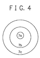
- a double-cladding fiber 7 in Fig. 1 is composed of a core 7a, a first clad 7b and a second clad 7c.
- the core 7a transmits a signal light and has a "n7a" refractive index.
- a small amount of rare-earth element is doped in the core 7a.
- the core 7a is covered with the first clad 7b whose refractive index is "n7b"; the first clad 7b is covered with the second clad 7c whose refractive index is "n7c".
- the refractive indices are related such that "n7a" > "n7b” > "n7c”.
- a light used for amplification is input to the first clad 7b.
- the pumping light pumps the rare-earth element in the core 7a and acts to amplify the signal light.
- the second clad 7c is provided to keep the pumping light within the first clad 7b.
- a signal light is input to the core 7a of a double-cladding fiber 7 from a transmission line 1a via an optical splitter 2, an isolator 4, a wavelength-division multiplex (WDM) coupler 5.
- the inputted signal light is split at the optical splitter 2; a part of the inputted signal light is inputted to a photodiode for monitoring input 3.
- WDM wavelength-division multiplex
- the WDM coupler 5 is connected to a pumping laser diode 6, and makes a pumping light power of the pumping laser diode 6 optically coupled to the first clad 7b of the double-cladding fiber 7. Almost all the output from the double-cladding fiber 7 is an amplified signal light, but a part of the pumping light is leaked without being used for amplification.
- This amplified signal light is outputted to a transmission line 1b via an isolator 8 and an optical splitter 9. At the optical splitter 9, the amplified signal light is split and a part of the amplified signal light is inputted to a photodiode for monitoring output 10 of the amplified signal light.
- a designated length of the second clad 7c is removed, and a substance whose refractive index is "n" ("n" > n7b) is coated on the part of the first clad 7b from which the second clad has been removed.
- the signal light has a wavelength in the 1550-nm band and is inputted to the double-cladding fiber 7 from the transmission line 1a via a fusing coupler in the optical splitter 2, which splits the signal light in a ratio of about nine-to-one, the isolator 4 and the WDM coupler 5.
- the optical splitter 2 about 10% of the inputted signal light is inputted to the photodiode for monitoring input 3.
- the sectional structure of the double-cladding fiber 7 used in this embodiment is composed of the core 7a, the first clad 7b and the second clad 7c, as shown in Fig. 2, and the core and the clads are concentric circles, and their diameters ⁇ are about 4 ⁇ m, 125 ⁇ m and 185 ⁇ m, respectively.
- a small amount of rare-earth element is doped in the core 7a for transmitting the signal light, whose refractive index is "n7a".
- erbium is doped as the rare-earth element. Therefore, as the pumping laser diode 6, a laser diode having a 1480-nm wavelength band is adopted for pumping the erbium. And at the output end 71 of the double-cladding fiber 7, about 50 mm of the second clad 7c is removed mechanically, and the output end 71 is fused with the input end fiber of the isolator 8, in which the fiber diameter is about 125 ⁇ m.
- the part from which the second clad 7c is removed is coated with an epoxy resin whose refractive index is about 1.6.
- An output end of the isolator 8 connects to a fusing coupler of the optical splitter 9, which splits the amplified signal light into a ratio of about nine-to-one, and about 10% of the amplified signal light is outputted to the photodiode for monitoring output 10. The remaining about 90% is output to the transmission line 1b.
- neodymium (Nd) can be used instead of erbium (Er).
- a 0.8- ⁇ m band must be used as the wavelength of the signal light, and a 1.1- ⁇ m band must be used as the wavelength of the pumping laser diode 6.
- a 980-nm band can be used instead of a 1480-nm band.
- any adhesive or dielectric resin can be used to coat the output end 71 of the double-cladding fiber 7. Furthermore, from the view point of light absorption, a following process has the same effect, that is, a metal film made of chromium (Cr) or titanium (Ti) is formed on the outer surface of the first clad 7b by vapor deposition, or a conductive resin whose main material is silver is coated on the outer surface of the first clad 7b.
- a signal light of a 1.55- ⁇ m band for example, having a wavelength of 1545 nm, is input to the core 7a of the double-cladding fiber 7 from the transmission line 1a via the optical splitter 2, the isolator 4 and the WDM coupler 5.
- a pumping light from the pumping laser diode 6 is inputted to the first clad 7b of the double-cladding fiber 7 from the same side of the signal light via the WDM coupler 5. At this time, a part of the pumping light is also inputted to the core 7a of the double-cladding fiber 7.
- the pumping light transmits in a zigzag inside of the first clad 7b; in this process, the pumping light transmits across the core 7a.
- the energy is transferred to the signal light via erbium; therefore, the signal light is amplified.
- the pumping light transmits in a multi-mode, and a part of the pumping light not transmitted across the core 7a remains, and this remaining part is output with the amplified signal light.
- the length of about 50 mm of the second clad 7c is removed, and the part of the first clad 7b from which the second clad 7c is removed is coated with an adhesive, whose refractive index is 1.6. Therefore, at this about-50-mm-length region, the pumping light transmitted in the first clad 7b leaks to the adhesive side. As a result, the pumping light is not output from the output end of the first clad 7b.
- the signal light transmitted in the core 7a is not influenced by the adhesive in a relationship with the refractive index of the first clad 7b, and is outputted.
- a signal-to-noise ratio (SNR) of the signal light in the transmission line 1b is measured by using an oscilloscope.
- the SNR was about 9 dB.
- the SNR is largely improved to 11dB.
- the following process can be applied; a silver paste is coated onto where the part has been removed, or a metal film made of chromium (Cr) or titanium (Ti) is formed by vapor deposition or is sputtered onto that area. These processes have also the effect of removing the pumping light.
- the present invention can realize an equivalent effect to a pumping-light cut filter with a simple structure of a double-cladding fiber and an optical fiber amplifier.
- the second clad 7c of the output end 71 of the double-cladding fiber 7 is removed, and a substance having a higher refractive index than the first clad 7b is coated on where the part was removed. With this, the pumping light is cut and the SNR of the outputting signal light can be largely improved.
- the surrounding surface of the core 7a transmitting the signal light is covered with the first clad 7b whose refractive index is "n7b", and the first clad 7b is covered with the second clad 7c.
- a designated length of the output end of the second clad 7c is removed, and a substance whose refractive index is "n" ("n" > "n7b") is coated on the first clad 7b at the removed part of second clad 7c.
- a double-cladding fiber and an optical fiber amplifier which have an equivalent function to a pumping-light cut filter with a simple structure, are provided.
- a core transmitting a signal light is covered with a first clad having a refractive index of n7b.
- This first clad is covered with a second clad.
- a designated length of the second clad is removed and a substance having a refractive index of "n" ("n" > n7b) is coated on the first clad on the part from which the second clad is removed.
Landscapes
- Physics & Mathematics (AREA)
- Optics & Photonics (AREA)
- General Physics & Mathematics (AREA)
- Electromagnetism (AREA)
- Engineering & Computer Science (AREA)
- Plasma & Fusion (AREA)
- Lasers (AREA)
- Optical Fibers, Optical Fiber Cores, And Optical Fiber Bundles (AREA)
Abstract
Description
Claims (11)
- A double-cladding fiber, comprising:a core for transmitting a signal light and having a first refractive index n7a;a first clad surrounding the core and having a second refractive index n7b; and,a second clad surrounding the first clad and having a third refractive index n7c;
wherein said second clad is absent from a length of the double-cladding fiber, and
wherein that part of the first clad from which the second clad is absent is coated with a substance which in operation effects removal of light passing along the first clad. - A double-cladding fiber, comprising:a core for transmitting a signal light and having a first refractive index n7a;a first clad surrounding the core and having a second refractive index n7b; and,a second clad surrounding the first clad and having a third refractive index n7c;
wherein said second clad is absent from a length of the double-cladding fiber, and
wherein that part of the first clad from which the second clad is absent is coated with a substance whose refractive index is greater than that (n7b) of the first clad. - An optical fiber amplifier, comprising:a wavelength-division multiplex (WDM) coupler, to which a signal light and a pumping light are inputted;an isolator from which an amplified signal light is outputted; and,a double-cladding fiber which connects between said WDM coupler and said isolator, and consists of:a core, whose refractive index is n7a;a first clad, whose refractive index is n7b, surrounding said core; and,a second clad, whose refractive index is n7c, surrounding said first clad;
wherein a length of said second clad is absent from said double-cladding fiber, and
wherein a length of the first clad from which the second clad is absent is coated with a substance which in operation effects removal of light passing along the first clad. - An optical fiber amplifier, comprising:a wavelength-division multiplex (WDM) coupler, to which a signal light and a pumping light are inputted;an isolator from which an amplified signal light is outputted; and,a double-cladding fiber which connects between said WDM coupler and said isolator, and consists of:a core, whose refractive index is n7a;a first clad, whose refractive index is n7b, surrounding said core; and,a second clad, whose refractive index is n7c, surrounding said first clad;
wherein a length of said second clad is absent from said double-cladding fiber, and
wherein a length of the first clad from which the second clad is absent is coated with a substance whose refractive index is greater than that (n7b) of the first clad. - A double-cladding fiber or an optical fiber amplifier in accordance with claim 1 or 3, wherein the coating substance has a refractive index greater than that (n7b) of the first clad.
- A double-cladding fiber or an optical fiber amplifier in accordance with claim 5, wherein the coating substance is an adhesive resin.
- A double-cladding fiber or an optical fiber amplifier in accordance with claim 1 or 3, wherein the coating substance absorbs said light passing along the first clad.
- A double-cladding fiber or an optical fiber amplifier in accordance with claim 7, wherein the coating substance is a metal paste or film, for example, silver paste or a chromium or titanium film.
- A double-cladding fiber or an optical fiber amplifier in accordance with any preceding claim, wherein said refractive indices are related such that n7a > n7b > n7c.
- A double-cladding fiber or an optical fiber amplifier in accordance with any preceding claim, wherein a small amount of rare-earth element is doped in said core.
- A double-cladding fiber or an optical fiber amplifier in accordance with any preceding claim, wherein the second clad is absent from an output end of the double-cladding fiber.
Applications Claiming Priority (2)
| Application Number | Priority Date | Filing Date | Title |
|---|---|---|---|
| JP11052828A JP2000252559A (en) | 1999-03-01 | 1999-03-01 | Double clad fiber and optical fiber amplifier |
| JP5282899 | 1999-03-01 |
Publications (2)
| Publication Number | Publication Date |
|---|---|
| EP1033795A2 true EP1033795A2 (en) | 2000-09-06 |
| EP1033795A3 EP1033795A3 (en) | 2001-10-17 |
Family
ID=12925722
Family Applications (1)
| Application Number | Title | Priority Date | Filing Date |
|---|---|---|---|
| EP00301646A Withdrawn EP1033795A3 (en) | 1999-03-01 | 2000-03-01 | Double cladding optical fiber and optical fiber amplifier |
Country Status (3)
| Country | Link |
|---|---|
| US (1) | US6335822B1 (en) |
| EP (1) | EP1033795A3 (en) |
| JP (1) | JP2000252559A (en) |
Cited By (2)
| Publication number | Priority date | Publication date | Assignee | Title |
|---|---|---|---|---|
| GB2379279A (en) * | 2001-08-31 | 2003-03-05 | Gsi Lumonics Ltd | Layered optical fibres with varied refractive indices used in laser processing system |
| US8724863B2 (en) | 2005-09-29 | 2014-05-13 | Trumpf Laser Gmbh + Co. Kg | Optical fiber having cladding scattering centers |
Families Citing this family (23)
| Publication number | Priority date | Publication date | Assignee | Title |
|---|---|---|---|---|
| JP3952033B2 (en) * | 2004-04-02 | 2007-08-01 | 松下電器産業株式会社 | Optical amplification fiber, optical amplification method, laser oscillation method, laser amplification device, laser oscillation device, laser device, and laser processing machine |
| US20080013586A1 (en) * | 2005-09-06 | 2008-01-17 | Spence David E | Narrow band diode pumping of laser gain materials |
| US7440176B2 (en) * | 2006-02-17 | 2008-10-21 | Newport Corporation | Bi-directionally pumped optical fiber lasers and amplifiers |
| US7680170B2 (en) * | 2006-06-15 | 2010-03-16 | Oclaro Photonics, Inc. | Coupling devices and methods for stacked laser emitter arrays |
| US20070291373A1 (en) * | 2006-06-15 | 2007-12-20 | Newport Corporation | Coupling devices and methods for laser emitters |
| US7866897B2 (en) * | 2006-10-06 | 2011-01-11 | Oclaro Photonics, Inc. | Apparatus and method of coupling a fiber optic device to a laser |
| JP2008171985A (en) * | 2007-01-11 | 2008-07-24 | Fujikura Ltd | Residual light removing fiber, residual light removing structure and optical amplifier using the same, and fiber laser |
| JP5260885B2 (en) * | 2007-04-24 | 2013-08-14 | 古河電気工業株式会社 | Optical fiber leakage light processing structure |
| JP5124225B2 (en) | 2007-05-15 | 2013-01-23 | 株式会社フジクラ | Optical fiber fusion splicing structure |
| US8027557B2 (en) | 2007-09-24 | 2011-09-27 | Nufern | Optical fiber laser, and components for an optical fiber laser, having reduced susceptibility to catastrophic failure under high power operation |
| JP4982330B2 (en) * | 2007-11-02 | 2012-07-25 | 株式会社フジクラ | Optical fiber fusion splicing structure, residual pumping light removal method, optical amplifier and optical fiber laser |
| WO2009079567A2 (en) * | 2007-12-17 | 2009-06-25 | Newport Corporation | Laser emitter modules and methods of assembly |
| US8804246B2 (en) * | 2008-05-08 | 2014-08-12 | Ii-Vi Laser Enterprise Gmbh | High brightness diode output methods and devices |
| JP5294114B2 (en) * | 2009-01-26 | 2013-09-18 | 株式会社メガオプト | Optical module |
| US9166365B2 (en) | 2010-01-22 | 2015-10-20 | Ii-Vi Laser Enterprise Gmbh | Homogenization of far field fiber coupled radiation |
| JP5416286B2 (en) * | 2010-10-29 | 2014-02-12 | 古河電気工業株式会社 | Optical amplification device and optical transmission system |
| US8644357B2 (en) | 2011-01-11 | 2014-02-04 | Ii-Vi Incorporated | High reliability laser emitter modules |
| US9031098B1 (en) * | 2011-12-15 | 2015-05-12 | Sandia Corporation | All fiber passively Q-switched laser |
| US20140338297A1 (en) * | 2013-05-17 | 2014-11-20 | U.S. Environmental Protection Agency | Artifact free inert filter medium for collection of organic particles |
| KR101787874B1 (en) * | 2016-02-29 | 2017-10-20 | 한양대학교 산학협력단 | Noise reduction collimator and imaging catheter system |
| KR101971777B1 (en) * | 2017-04-28 | 2019-04-23 | 한양대학교 산학협력단 | Imaging catheter system |
| JP2020134722A (en) * | 2019-02-20 | 2020-08-31 | 株式会社フジクラ | Optical devices and laser devices |
| CN112965085B (en) * | 2021-02-05 | 2022-06-10 | 山东国耀量子雷达科技有限公司 | Laser radar receiving module, laser radar and atmospheric aerosol detection method |
Family Cites Families (20)
| Publication number | Priority date | Publication date | Assignee | Title |
|---|---|---|---|---|
| US5363463A (en) * | 1982-08-06 | 1994-11-08 | Kleinerman Marcos Y | Remote sensing of physical variables with fiber optic systems |
| US4820018A (en) * | 1987-10-30 | 1989-04-11 | Gte Laboratories Incorporated | Optical fiber for light amplification |
| GB2239983A (en) * | 1989-12-22 | 1991-07-17 | Univ Southampton | Optical fibre laser |
| DK168180B1 (en) * | 1991-07-19 | 1994-02-21 | Lycom As | Method of amplifying an optical signal, optical amplifier for practicing the method, and using such an optical amplifier as a light source |
| GB2273389B (en) * | 1992-12-14 | 1996-07-17 | Pirelli Cavi Spa | Rare earth doped optical fibre amplifiers |
| JP3556026B2 (en) * | 1995-10-30 | 2004-08-18 | 富士通株式会社 | Multi-wavelength optical amplifier that amplifies multiple wavelength signals at once |
| JPH1051062A (en) | 1996-08-05 | 1998-02-20 | Mitsubishi Cable Ind Ltd | Optical fiber for amplification |
| JP3300608B2 (en) | 1996-08-05 | 2002-07-08 | 三菱電線工業株式会社 | Optical fiber for amplification |
| US5708669A (en) * | 1996-09-24 | 1998-01-13 | Lucent Technologies Inc. | Article comprising a cladding-pumped optical fiber laser |
| US5877890A (en) * | 1996-10-30 | 1999-03-02 | Rutgers, The State University Of New Jersey | Optical-fiber amplifier having high-saturation output |
| ATE381132T1 (en) * | 1997-02-13 | 2007-12-15 | Koheras As | ACTIVE OPTICAL WAVEGUIDE WITH ASYMMETRIC POLARIZATION, PROCESS OF PRODUCTION THEREOF AND ITS USE. |
| US5892615A (en) * | 1997-03-17 | 1999-04-06 | Sdl, Inc. | Output power enhancement in optical fiber lasers |
| DE19723267A1 (en) * | 1997-06-03 | 1998-12-10 | Heidelberger Druckmasch Ag | Method and arrangement for reducing the pump light at the exit of a fiber laser |
| JPH10339819A (en) * | 1997-06-05 | 1998-12-22 | Furukawa Electric Co Ltd:The | Optical fiber for optical amplification |
| US5898715A (en) * | 1997-06-09 | 1999-04-27 | Lucent Technologies Inc. | Optical communication system comprising a cladding pumped fiber laser |
| US5857053A (en) * | 1997-06-17 | 1999-01-05 | Lucent Technologies Inc. | Optical fiber filter |
| JPH11121839A (en) * | 1997-10-17 | 1999-04-30 | Fujitsu Ltd | Optical amplification fiber and optical fiber amplifier |
| US6031849A (en) * | 1997-11-14 | 2000-02-29 | Jds Uniphase Corporation | High power three level fiber laser and method of making same |
| US5949941A (en) * | 1997-11-21 | 1999-09-07 | Lucent Technologies Inc. | Cladding-pumped fiber structures |
| FR2778751B1 (en) * | 1998-05-14 | 2000-06-16 | Alsthom Cge Alcatel | OPTICAL FIBER FOR FLAT GAIN OPTICAL AMPLIFIER |
-
1999
- 1999-03-01 JP JP11052828A patent/JP2000252559A/en active Pending
-
2000
- 2000-02-29 US US09/515,832 patent/US6335822B1/en not_active Expired - Fee Related
- 2000-03-01 EP EP00301646A patent/EP1033795A3/en not_active Withdrawn
Cited By (3)
| Publication number | Priority date | Publication date | Assignee | Title |
|---|---|---|---|---|
| GB2379279A (en) * | 2001-08-31 | 2003-03-05 | Gsi Lumonics Ltd | Layered optical fibres with varied refractive indices used in laser processing system |
| GB2379279B (en) * | 2001-08-31 | 2005-10-26 | Gsi Lumonics Ltd | Laser processing system and optical fibres |
| US8724863B2 (en) | 2005-09-29 | 2014-05-13 | Trumpf Laser Gmbh + Co. Kg | Optical fiber having cladding scattering centers |
Also Published As
| Publication number | Publication date |
|---|---|
| US6335822B1 (en) | 2002-01-01 |
| EP1033795A3 (en) | 2001-10-17 |
| JP2000252559A (en) | 2000-09-14 |
Similar Documents
| Publication | Publication Date | Title |
|---|---|---|
| EP1033795A2 (en) | Double cladding optical fiber and optical fiber amplifier | |
| US11073656B2 (en) | Optical coupler and optical amplifier | |
| CA2020759C (en) | Erbium-doped fiber amplifier coupling device | |
| EP1935068B1 (en) | Optical fibre laser | |
| US5216728A (en) | Optical fiber amplifier with filter | |
| US11402585B2 (en) | Optical connection structure | |
| US20080267227A1 (en) | Gain-clamped optical amplifier using double-clad fiber | |
| KR100360983B1 (en) | Optical fiber Amplifier for Long-wavelength band | |
| US6546168B1 (en) | Integrated isolator fused coupler method and apparatus | |
| KR100442624B1 (en) | Gain flattening filter and gain flattened optical fiber amplifier using it | |
| JP2001230476A (en) | Optical amplifier | |
| US6513991B1 (en) | Semiconductor optical device package | |
| AU640073B2 (en) | Optical amplifier | |
| US20030174388A1 (en) | Single-source multiple-order raman amplifier for optical transmission systems | |
| US8004753B2 (en) | Optical amplifier, fiber laser, and method of eliminating reflected light | |
| US6217204B1 (en) | Optical fiber assembly and light amplification coupler having rare earth doped light amplification medium and related method of making | |
| JP2955780B2 (en) | Optical fiber amplifier | |
| US6178039B1 (en) | Light source module and an optical amplifier using the same | |
| US6532107B2 (en) | Optical amplifier, light source module and optical system | |
| JP2000286489A (en) | Optical amplifier | |
| JP2740676B2 (en) | Optical amplification transmission circuit | |
| JP2694014B2 (en) | Bidirectional optical amplifier transmission circuit | |
| JP2744471B2 (en) | Optical amplification transmission circuit | |
| KR100271516B1 (en) | Optical fiber type optical-coupler coupling edf and common optical fiber | |
| JP2002084023A (en) | Optical fiber amplifier, excitation light source module and optical system |
Legal Events
| Date | Code | Title | Description |
|---|---|---|---|
| PUAI | Public reference made under article 153(3) epc to a published international application that has entered the european phase |
Free format text: ORIGINAL CODE: 0009012 |
|
| AK | Designated contracting states |
Kind code of ref document: A2 Designated state(s): FR GB IT Kind code of ref document: A2 Designated state(s): AT BE CH CY DE DK ES FI FR GB GR IE IT LI LU MC NL PT SE |
|
| AX | Request for extension of the european patent |
Free format text: AL;LT;LV;MK;RO;SI |
|
| PUAL | Search report despatched |
Free format text: ORIGINAL CODE: 0009013 |
|
| AK | Designated contracting states |
Kind code of ref document: A3 Designated state(s): AT BE CH CY DE DK ES FI FR GB GR IE IT LI LU MC NL PT SE |
|
| AX | Request for extension of the european patent |
Free format text: AL;LT;LV;MK;RO;SI |
|
| 17P | Request for examination filed |
Effective date: 20011112 |
|
| AKX | Designation fees paid |
Free format text: FR GB IT |
|
| REG | Reference to a national code |
Ref country code: DE Ref legal event code: 8566 |
|
| STAA | Information on the status of an ep patent application or granted ep patent |
Free format text: STATUS: THE APPLICATION HAS BEEN WITHDRAWN |
|
| 18W | Application withdrawn |
Effective date: 20021217 |