EP1033733A2 - Forward/reverse circuit for dpdt type switch - Google Patents
Forward/reverse circuit for dpdt type switch Download PDFInfo
- Publication number
- EP1033733A2 EP1033733A2 EP00301650A EP00301650A EP1033733A2 EP 1033733 A2 EP1033733 A2 EP 1033733A2 EP 00301650 A EP00301650 A EP 00301650A EP 00301650 A EP00301650 A EP 00301650A EP 1033733 A2 EP1033733 A2 EP 1033733A2
- Authority
- EP
- European Patent Office
- Prior art keywords
- terminal
- contacts
- circuit
- power source
- assembly according
- Prior art date
- Legal status (The legal status is an assumption and is not a legal conclusion. Google has not performed a legal analysis and makes no representation as to the accuracy of the status listed.)
- Granted
Links
Images

Classifications
-
- H—ELECTRICITY
- H01—ELECTRIC ELEMENTS
- H01H—ELECTRIC SWITCHES; RELAYS; SELECTORS; EMERGENCY PROTECTIVE DEVICES
- H01H1/00—Contacts
- H01H1/58—Electric connections to or between contacts; Terminals
-
- H—ELECTRICITY
- H01—ELECTRIC ELEMENTS
- H01H—ELECTRIC SWITCHES; RELAYS; SELECTORS; EMERGENCY PROTECTIVE DEVICES
- H01H9/00—Details of switching devices, not covered by groups H01H1/00 - H01H7/00
- H01H9/02—Bases, casings, or covers
- H01H9/06—Casing of switch constituted by a handle serving a purpose other than the actuation of the switch, e.g. by the handle of a vacuum cleaner
- H01H9/063—Casing of switch constituted by a handle serving a purpose other than the actuation of the switch, e.g. by the handle of a vacuum cleaner enclosing a reversing switch
-
- H—ELECTRICITY
- H01—ELECTRIC ELEMENTS
- H01H—ELECTRIC SWITCHES; RELAYS; SELECTORS; EMERGENCY PROTECTIVE DEVICES
- H01H9/00—Details of switching devices, not covered by groups H01H1/00 - H01H7/00
- H01H9/02—Bases, casings, or covers
- H01H9/06—Casing of switch constituted by a handle serving a purpose other than the actuation of the switch, e.g. by the handle of a vacuum cleaner
- H01H2009/065—Battery operated hand tools in which the battery and the switch are directly connected
Definitions
- the present invention relates to power tools and, more specifically, to switch assemblies used to energize power tools.
- All power tools include switch mechanisms between the power source and motor to energize the motor and, in turn, rotate or move an output.
- Various types of trigger, slide, toggle or the like switches are utilized in power tools. Also, some of these switches provide a reverse pathway so that the motor may be utilized in a reversing direction.
- the switches are positioned in a housing and have various types of wire leads connected to them. The leads may include connectors or have soldered connections. Also, the switches may be coupled by a lead wire, which has both connectors and is also soldered. These connections, especially in small tools, require space as well as relatively expensive manufacturing costs. This is due to the fact that the wires and connectors require relatively large spaces. Also, they require labor extensive operations to be performed to couple the switch with the power source in the motor. Thus, it would be desirable to have an inexpensive connection between the switch, power source and motor which is compact and easily installed.
- a connector assembly which includes an integral circuit coupled to a switch and a terminal, which couples to a power source.
- the present invention provides a connector assembly which is compact, easily manufactured, and reduces assembly issues.
- the present invention provides a connector assembly which easily directly couples with a switch and to a power source such as a battery.
- a switch assembly comprises a reversible switch including an activation member, electronics, and a plurality of contacts coupled with the electronics.
- the contacts also couple the reversible switch with a power source and a motor.
- a first one-piece terminal circuit is formed in a desired configuration.
- a first portion of the first terminal circuit is coupled with a plurality of the plurality of contacts.
- the second portion of the first terminal circuit is directly coupled with the power source.
- a second one-piece terminal circuit is formed in a desired configuration.
- a first portion of the second terminal circuit is coupled with a second plurality of the plurality of contacts. The second plurality of contacts being different from the first plurality of contacts and a second portion of the second terminal circuit directly coupled with a power source.
- the first and second terminal circuits are stamped metallic parts.
- the first portion of the terminal circuits is substantially planar with two apertures to receive two contacts from the plurality of contacts on the switch.
- a second portion of the first terminal circuit is continuous and extends substantially coplanar with the first portion of the terminal circuit.
- a member is formed at the end of the second portion to couple with the power source.
- the second terminal circuit second portion is continuous and extends substantially perpendicular from the first portion and includes a projection member to couple with the power source.
- the first portion of the first and second terminal circuits are positioned on top of one another and are separated by an insulation member.
- a switch assembly comprises a reversible switch which includes an activation member, electronics and a plurality of contacts coupled with the electronics. Also, the contacts are adapted to couple the reversible switch with the power source and a motor.
- a pair of formed rigid terminal circuits have a desired configuration. Each terminal circuit has a first portion to couple with a plurality of contacts. Each first portion is coupled with a different plurality of contacts. Each of the terminal circuits has a second portion to directly couple with a power source. Both terminal circuits are stamped metallic parts. The first portions of the pair are substantially planar and include a pair of apertures to receive the plurality of contacts. The second portion of the first terminal circuit is continuous with and substantially coplanar with the first portion.
- a terminal end is coupled with the second portion to couple the terminal with the power source.
- the second terminal circuit has a second portion which is continuous and substantially perpendicular to the first portion. Also, it includes a projection member in contact with the power source. Further, an insulation member is sandwiched between the first portions of the terminal circuits.
- a power tool comprises a housing, a motor in the housing, an output coupled wit the motor, a power source coupled with the motor, and a switch assembly coupled wit the power source and the motor.
- the switch assembly enables energizing of the motor to drive the output.
- the switch assembly comprises a reversible switch which includes an activation member, electronics and a plurality of contacts coupled with the electronics. Also, the contacts are adapted to couple the reversible switch with the power source and a motor.
- a pair of formed rigid terminal circuits have a desired configuration. Each terminal circuit has a first portion to couple with a plurality of contacts. Each first portion is coupled with a different plurality of contacts.
- Each of the terminal circuits has a second portion to directly couple with a power source. Both terminal circuits are stamped metallic parts.
- the first portions of the pair are substantially planar and include a pair of apertures to receive the plurality of contacts.
- the second portion of the first terminal circuit is continuous with and substantially coplanar with the first portion.
- a terminal end is coupled with the second portion to couple the terminal with the power source.
- the second terminal circuit has a second portion which is continuous and substantially perpendicular to the first portion. Also, it includes a projection member in contact with the power source. Further, an insulation member is sandwiched between the first portions of the terminal surface.
- a connector assembly comprises a first one-piece connector having a circuit portion adapted to be coupled with a plurality of contacts.
- a terminal portion is continuous with the circuit portion and is adapted to be directly coupled with a positive terminal of the power source.
- a second one-piece connector has a first circuit portion adapted to be coupled with a plurality of contacts, the contacts being different from the ones which are connected to the first terminal circuit.
- a terminal portion is continuous with the circuit portion and is adapted to be directly coupled with a negative terminal of the power source.
- the connectors are stamped metallic parts.
- the first connector circuit portion is substantially planar with a pair of apertures to receive the plurality of contacts.
- the terminal portion extends coplanar with the circuit portion and includes an end adapted to couple with the positive battery terminal.
- the second connector circuit portion is substantially planar with a pair of apertures to receive the plurality of contacts.
- the terminal portion extends substantially perpendicular to the connector circuit portion and includes a projecting end adapted to couple with a negative battery terminal.
- An isolator is sandwiched between the first and second connector circuit portions.
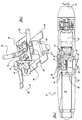
- the power tool includes a housing 12 which houses switch assembly 20.
- An output 16 is coupled with the motor 14.
- a battery 18 powers the motor 14 via a switch assembly 20.
- the switch assembly 20 includes an activation member 22, a body 24 which includes electronics (not shown), and contacts 26.
- a push button switch 28 may be coupled with the activation member 22.
- a frame 30 surrounds the switch body to couple the switch 20 with the housing 12. Terminals 32 and 34 are coupled with the contacts 26 and include power leads 36 and 38 which lead to the motor 14.
- a connector assembly 40 connects the switch 20 to the battery 18.
- the connector assembly 40 includes first and second terminal circuits 42 and 44.
- the first terminal circuit 42 includes a circuit portion 46 which has an overall L-shape and is substantially planar. Two apertures 48 and 50 enable the circuit portion 46 to couple with the contacts 26.
- the terminal portion 52 is continuous with the circuit portion 46 and extends substantially coplanar to the circuit portion 46.
- An end member 54 continuous with the terminal portion 52, has projecting members 56, 58, 60.
- the projecting members 56, 58, 60 couple the terminal end 54 with the positive terminal of the battery 18.
- the projections 56, 58, 60 extend at desired angles so that they are compressed and make sufficient contact with the positive battery terminal.
- the terminal circuit 44 includes a circuit portion 62 which has an overall L-shape and is substantially planar. Projecting members 64 and 66 include apertures 68 and 70. The apertures 68 and 70 couple with contacts 26, the contacts are different from those that couple with the first terminal circuit 42.
- the terminal portion 72 is continuous with and extends substantially perpendicular to the planar first circuit portion 62.
- the terminal portion 72 includes an extending portion 74 with an end 76.
- the portion 74 has a desired, preferably arcuate, configuration so that it projects to contact the negative terminal of the battery 18.
- the circuit portions directly couple with the switch contacts 26.
- the terminal portions contact directly with the battery 18. Accordingly, this provides a compact switch assembly which eliminates the need for costly wire leads and wire connectors. Also, the present assembly enables easy manufacturing, enabling the circuit portion to be coupled with the contacts and soldered.
- Insulation members 80 and 82 are sandwiched with respect to the first and second terminal contacts 42 and 44.
- the insulation member 80 is positioned between the two circuit portions 46 and 62.
- the second insulation member 82 is positioned on top of the second terminal circuit 44.
- the insulation isolators provide electrical insulation so that the contacts do not touch one another.
Abstract
Description
Claims (20)
- A switch assembly comprising:a reversible switch including an activation member, electronics, and a plurality of contacts coupled with said electronics and for coupling the reversible switch with a power source;a first one-piece terminal circuit formed in a desired configuration, a first portion of said first terminal circuit coupling with a plurality of said plurality of contacts,a second portion of said first terminal circuit directly coupled with the power source;a second one-piece terminal circuit formed in a desired configuration, a first portion of said second terminal circuit coupled with a second plurality of said plurality of contacts different from said first plurality of contacts, and a second portion of said second terminal circuit directly coupled with the power source.
- The switch assembly according to Claim 1, wherein said first terminal circuit is a stamped metallic part.
- The switch assembly according to either of the preceding claims, wherein said first portion of said first terminal circuit being substantially planar with two apertures for receiving two contacts from said plurality of contacts.
- The switch assembly according to any one of the preceding claims, wherein said second portion of said first terminal circuit extends substantially coplanar from said first portion of said first terminal circuit and includes a member for coupling with said power source.
- The switch assembly according to any one of the preceding claims, wherein said second terminal circuit is a stamped metallic part.
- The switch assembly according to any one of the preceding claims, wherein said first portion of said second terminal circuit is substantially planar and includes two apertures for coupling with said contacts.
- The switch assembly according to any one of the preceding claims, wherein said second portion of said second terminal circuit extends substantially perpendicular from said first portion and includes projecting members for coupling with a power source.
- The switch assembly according to any one of Claim 1 to 6, wherein said first portions of said first and second terminal circuits are positioned on top of the other separated by insulation a member.
- A switch assembly comprising:a reversible switch including an activation member, electronics, and a plurality of contacts coupled with said electronics and for coupling the reversible switch with a power source;a pair of formed rigid terminal circuits having a desired configuration, each having a first portion for coupling with a plurality of said contacts, each first portion coupled with a different plurality of contacts, each having a second portion for directly coupling with the power source.
- The switch assembly according to Claim 9, wherein both terminal circuits are stamped metallic parts.
- The switch assembly according to either Claim 9 or Claim 10, wherein said first portions are substantially planar and include a pair of apertures for receiving said plurality of contacts.
- The switch assembly according to any one of Claims 9 to 11, wherein said second portion extends substantially coplanar from said first portion and includes a member for coupling with said power source.
- The switch assembly according to any one of Claims 9 to 11, wherein said second portion extends substantially perpendicular from said first portion and includes projecting members for coupling with a power source.
- The switch assembly according to any one of Claims 9 to 11, wherein said first portions of said first and second terminal circuits are positioned on top of the other separated by insulation a member.
- A power tool comprising:a switch assembly according to any one of Claims 9 to 14;a housing;a motor in said housing;an output coupled with said motor; anda power source coupled with said motor;
wherein said switch assembly is coupled with said power source and said motor, said switch assembly enabling energizing of said motor for driving said output. - A connector assembly comprising:a first one-piece connector having a circuit portion adapted to be coupled with a plurality of contacts, and a terminal portion continuous with said circuit portion adapted to be directly coupled with a positive terminal of a power source;a second one-piece connector having a circuit portion adapted to be coupled with a plurality of contacts, and a terminal portion continuous with said circuit portion adapted to be directly coupled with a negative terminal of the power source.
- The connector assembly according to Claim 21, wherein said connectors are stamped metallic parts.
- The connector assembly according to either Claim 16 or Claim 17, wherein said first connector circuit portion being substantially planar with a pair of apertures for receiving said plurality of contacts and said terminal portion extending coplanar with said circuit portion and including an end adapted to couple with a positive battery terminal.
- The connector assembly according to any one of Claims 16 to 18, wherein said second connector circuit portion being substantially planar with a pair of apertures for receiving said plurality of contacts and said terminal portion extending substantially perpendicular to said connector circuit portion and including a projecting end adapted to be coupled with a negative battery terminal.
- The connector assembly according to any one of Claims 16 to 19, wherein an insulator is sandwiched between said first and second connector circuit portions.
Applications Claiming Priority (2)
| Application Number | Priority Date | Filing Date | Title |
|---|---|---|---|
| US09/261,026 US6144122A (en) | 1999-03-02 | 1999-03-02 | Power tool with switch and electrical connector assemblies |
| US261026 | 1999-03-02 |
Publications (3)
| Publication Number | Publication Date |
|---|---|
| EP1033733A2 true EP1033733A2 (en) | 2000-09-06 |
| EP1033733A3 EP1033733A3 (en) | 2001-08-29 |
| EP1033733B1 EP1033733B1 (en) | 2010-05-05 |
Family
ID=22991666
Family Applications (1)
| Application Number | Title | Priority Date | Filing Date |
|---|---|---|---|
| EP00301650A Expired - Lifetime EP1033733B1 (en) | 1999-03-02 | 2000-03-01 | Forward/reverse circuit for dpdt type switch |
Country Status (8)
| Country | Link |
|---|---|
| US (1) | US6144122A (en) |
| EP (1) | EP1033733B1 (en) |
| CN (1) | CN1230846C (en) |
| AT (1) | ATE467222T1 (en) |
| AU (1) | AU760499B2 (en) |
| CA (1) | CA2299147C (en) |
| DE (1) | DE60044315D1 (en) |
| HK (1) | HK1028485A1 (en) |
Families Citing this family (15)
| Publication number | Priority date | Publication date | Assignee | Title |
|---|---|---|---|---|
| DE20321118U1 (en) * | 2003-09-29 | 2005-12-22 | Robert Bosch Gmbh | Cordless drill/driver, comprising spring supported switch extending across full front of handle |
| DE102004051913A1 (en) † | 2004-08-09 | 2006-02-23 | Robert Bosch Gmbh | Cordless Screwdriver |
| DE102006023187B4 (en) | 2005-05-17 | 2020-02-27 | Milwaukee Electric Tool Corp. | Method for operating a battery charger and a combination comprising a battery and a battery charger |
| DE102006023188A1 (en) | 2005-05-17 | 2007-01-11 | Milwaukee Electric Tool Corp., Brookfield | Power tool, battery, charger and method of operation thereof |
| US20070084616A1 (en) * | 2005-10-14 | 2007-04-19 | Lam Chin H | Handheld rotary tool |
| US7696721B2 (en) * | 2005-11-08 | 2010-04-13 | Emerson Electric Co. | Switching method and apparatus for AC/DC powered corded/cordless appliance and related apparatus |
| US7854274B2 (en) | 2007-11-21 | 2010-12-21 | Black & Decker Inc. | Multi-mode drill and transmission sub-assembly including a gear case cover supporting biasing |
| US7717191B2 (en) | 2007-11-21 | 2010-05-18 | Black & Decker Inc. | Multi-mode hammer drill with shift lock |
| US7735575B2 (en) | 2007-11-21 | 2010-06-15 | Black & Decker Inc. | Hammer drill with hard hammer support structure |
| US7762349B2 (en) | 2007-11-21 | 2010-07-27 | Black & Decker Inc. | Multi-speed drill and transmission with low gear only clutch |
| US7717192B2 (en) | 2007-11-21 | 2010-05-18 | Black & Decker Inc. | Multi-mode drill with mode collar |
| US7770660B2 (en) | 2007-11-21 | 2010-08-10 | Black & Decker Inc. | Mid-handle drill construction and assembly process |
| US7798245B2 (en) | 2007-11-21 | 2010-09-21 | Black & Decker Inc. | Multi-mode drill with an electronic switching arrangement |
| DE102009054967A1 (en) * | 2009-12-18 | 2011-06-22 | Robert Bosch GmbH, 70469 | Machine tool with electric drive motor |
| US11431224B2 (en) * | 2017-02-15 | 2022-08-30 | Black & Decker Inc. | Power and home tools |
Citations (2)
| Publication number | Priority date | Publication date | Assignee | Title |
|---|---|---|---|---|
| US4683352A (en) | 1985-07-17 | 1987-07-28 | Fujisoku Electric Co., Ltd. | Changeover switch |
| US4937705A (en) | 1989-05-08 | 1990-06-26 | Eaton Corporation | Variable power control apparatus having external heat sink mounting battery clips |
Family Cites Families (18)
| Publication number | Priority date | Publication date | Assignee | Title |
|---|---|---|---|---|
| US3437772A (en) * | 1966-06-06 | 1969-04-08 | Cutler Hammer Inc | Contact structure for electrical switching device and method of assembly |
| GB1435697A (en) * | 1972-09-02 | 1976-05-12 | Lucas Electrical Ltd | Electrical switches |
| DE2360746A1 (en) * | 1973-12-06 | 1975-06-12 | Bbc Brown Boveri & Cie | Termination/interconnection contact - produced from single sheet metal to provide wedging contact, screw terminal, flat-plug socket |
| JPS62106Y2 (en) * | 1979-07-20 | 1987-01-06 | ||
| JPH0347218Y2 (en) * | 1985-09-26 | 1991-10-08 | ||
| JPS63194443U (en) * | 1987-06-01 | 1988-12-14 | ||
| US4808775A (en) * | 1987-08-03 | 1989-02-28 | Toyo Denso Kabushiki Kaisha | Reversing switch |
| US4874911A (en) * | 1988-03-28 | 1989-10-17 | Eaton Corporation | Electrical reversing switch |
| DE3842406A1 (en) * | 1988-12-16 | 1990-06-21 | Philips Patentverwaltung | DEVICE FOR CONNECTING A COAXIAL CABLE |
| JPH0715073Y2 (en) * | 1989-04-26 | 1995-04-10 | 株式会社東海理化電機製作所 | Load drive |
| US5013266A (en) * | 1990-01-16 | 1991-05-07 | Augat, Inc. | Twisted terminal for switching device |
| US5601183A (en) * | 1991-11-15 | 1997-02-11 | Eaton Corporation | Two-pole make-before-break switch |
| DE4312423B4 (en) * | 1993-04-16 | 2012-08-30 | A. & H. Meyer GmbH Leuchten und Büroelektrik | Contact rail for electrical installation devices, in particular in socket boxes |
| DE4340032C1 (en) * | 1993-11-24 | 1994-09-01 | Hella Kg Hueck & Co | Electrical connector |
| DE4425880A1 (en) * | 1994-07-12 | 1996-01-18 | Wago Verwaltungs Gmbh | Connector clamp with SMD contact |
| US5675225A (en) * | 1995-08-23 | 1997-10-07 | Moore; Herbert Arthur | Interactive pet toy |
| DE19533299A1 (en) * | 1995-09-08 | 1997-03-13 | Siemens Ag | Multi-pole variable SMD-type connector arrangement for vehicle control modules |
| DE19544357A1 (en) * | 1995-11-28 | 1997-06-05 | Gore W L & Ass Gmbh | Ribbon cable with shield connection |
-
1999
- 1999-03-02 US US09/261,026 patent/US6144122A/en not_active Expired - Lifetime
-
2000
- 2000-02-22 CA CA002299147A patent/CA2299147C/en not_active Expired - Fee Related
- 2000-03-01 AU AU19577/00A patent/AU760499B2/en not_active Ceased
- 2000-03-01 EP EP00301650A patent/EP1033733B1/en not_active Expired - Lifetime
- 2000-03-01 AT AT00301650T patent/ATE467222T1/en not_active IP Right Cessation
- 2000-03-01 DE DE60044315T patent/DE60044315D1/en not_active Expired - Lifetime
- 2000-03-02 CN CNB001068725A patent/CN1230846C/en not_active Expired - Fee Related
- 2000-12-09 HK HK00107926A patent/HK1028485A1/en not_active IP Right Cessation
Patent Citations (2)
| Publication number | Priority date | Publication date | Assignee | Title |
|---|---|---|---|---|
| US4683352A (en) | 1985-07-17 | 1987-07-28 | Fujisoku Electric Co., Ltd. | Changeover switch |
| US4937705A (en) | 1989-05-08 | 1990-06-26 | Eaton Corporation | Variable power control apparatus having external heat sink mounting battery clips |
Also Published As
| Publication number | Publication date |
|---|---|
| CA2299147A1 (en) | 2000-09-02 |
| DE60044315D1 (en) | 2010-06-17 |
| EP1033733B1 (en) | 2010-05-05 |
| CA2299147C (en) | 2009-04-28 |
| HK1028485A1 (en) | 2001-02-16 |
| AU1957700A (en) | 2000-09-07 |
| CN1230846C (en) | 2005-12-07 |
| US6144122A (en) | 2000-11-07 |
| EP1033733A3 (en) | 2001-08-29 |
| AU760499B2 (en) | 2003-05-15 |
| CN1267069A (en) | 2000-09-20 |
| ATE467222T1 (en) | 2010-05-15 |
Similar Documents
| Publication | Publication Date | Title |
|---|---|---|
| CA2299147C (en) | Forward/reverse circuit for dpdt type switch | |
| JP2001332358A (en) | Connector device | |
| WO2002013319A1 (en) | Wire connector | |
| US4937705A (en) | Variable power control apparatus having external heat sink mounting battery clips | |
| KR100791040B1 (en) | Low profile combination switch and connector assembly | |
| US20170271963A1 (en) | Handheld work apparatus having an electric motor | |
| JPH11126667A (en) | Electric contact | |
| EP1126487A3 (en) | Plug-in trip unit joint for a molded case circuit breaker | |
| JPS60160581A (en) | Charger | |
| MXPA00002176A (en) | Forward/reverse circuit for dpdt type switch | |
| JP4076183B2 (en) | Switch device-Printed wiring board-Combination | |
| EP0196305A1 (en) | Battery-switch module adapter | |
| EP1202309A3 (en) | Interlocking type multi-push-switch device | |
| JPH1141754A (en) | Three-dimensional circuit device | |
| US20060192439A1 (en) | Power control center with solid state device for controlling power transmission | |
| JP3338980B2 (en) | Three-dimensional circuit body and its relay terminal | |
| KR20050004882A (en) | Contact with a rigidly welded spring cage | |
| WO2003073588A3 (en) | Electric motor | |
| EP0217629A2 (en) | Electrical connector having cam actuated wire holding means | |
| JPH1116619A (en) | Connector mounting structure | |
| JP3081769B2 (en) | Electrical junction box | |
| EP1093975A3 (en) | Electric connection box | |
| JP3535035B2 (en) | Connector terminal locking structure | |
| KR200283071Y1 (en) | Device for connecting terminal of switch | |
| JP2861375B2 (en) | Flat cable connector |
Legal Events
| Date | Code | Title | Description |
|---|---|---|---|
| PUAI | Public reference made under article 153(3) epc to a published international application that has entered the european phase |
Free format text: ORIGINAL CODE: 0009012 |
|
| AK | Designated contracting states |
Kind code of ref document: A2 Designated state(s): AT BE CH CY DE DK ES FI FR GB GR IE IT LI LU MC NL PT SE |
|
| AX | Request for extension of the european patent |
Free format text: AL;LT;LV;MK;RO;SI |
|
| PUAL | Search report despatched |
Free format text: ORIGINAL CODE: 0009013 |
|
| AK | Designated contracting states |
Kind code of ref document: A3 Designated state(s): AT BE CH CY DE DK ES FI FR GB GR IE IT LI LU MC NL PT SE |
|
| AX | Request for extension of the european patent |
Free format text: AL;LT;LV;MK;RO;SI |
|
| AKX | Designation fees paid |
Free format text: AT BE CH CY DE DK ES FI FR GB GR IE IT LI LU MC NL PT SE |
|
| 17P | Request for examination filed |
Effective date: 20020611 |
|
| 17Q | First examination report despatched |
Effective date: 20070906 |
|
| GRAP | Despatch of communication of intention to grant a patent |
Free format text: ORIGINAL CODE: EPIDOSNIGR1 |
|
| GRAS | Grant fee paid |
Free format text: ORIGINAL CODE: EPIDOSNIGR3 |
|
| GRAA | (expected) grant |
Free format text: ORIGINAL CODE: 0009210 |
|
| AK | Designated contracting states |
Kind code of ref document: B1 Designated state(s): AT BE CH CY DE DK ES FI FR GB GR IE IT LI LU MC NL PT SE |
|
| REG | Reference to a national code |
Ref country code: GB Ref legal event code: FG4D |
|
| REG | Reference to a national code |
Ref country code: CH Ref legal event code: EP |
|
| REG | Reference to a national code |
Ref country code: IE Ref legal event code: FG4D |
|
| REF | Corresponds to: |
Ref document number: 60044315 Country of ref document: DE Date of ref document: 20100617 Kind code of ref document: P |
|
| REG | Reference to a national code |
Ref country code: NL Ref legal event code: VDEP Effective date: 20100505 |
|
| PG25 | Lapsed in a contracting state [announced via postgrant information from national office to epo] |
Ref country code: NL Free format text: LAPSE BECAUSE OF FAILURE TO SUBMIT A TRANSLATION OF THE DESCRIPTION OR TO PAY THE FEE WITHIN THE PRESCRIBED TIME-LIMIT Effective date: 20100505 Ref country code: SE Free format text: LAPSE BECAUSE OF FAILURE TO SUBMIT A TRANSLATION OF THE DESCRIPTION OR TO PAY THE FEE WITHIN THE PRESCRIBED TIME-LIMIT Effective date: 20100505 Ref country code: ES Free format text: LAPSE BECAUSE OF FAILURE TO SUBMIT A TRANSLATION OF THE DESCRIPTION OR TO PAY THE FEE WITHIN THE PRESCRIBED TIME-LIMIT Effective date: 20100816 |
|
| PG25 | Lapsed in a contracting state [announced via postgrant information from national office to epo] |
Ref country code: AT Free format text: LAPSE BECAUSE OF FAILURE TO SUBMIT A TRANSLATION OF THE DESCRIPTION OR TO PAY THE FEE WITHIN THE PRESCRIBED TIME-LIMIT Effective date: 20100505 Ref country code: FI Free format text: LAPSE BECAUSE OF FAILURE TO SUBMIT A TRANSLATION OF THE DESCRIPTION OR TO PAY THE FEE WITHIN THE PRESCRIBED TIME-LIMIT Effective date: 20100505 |
|
| PG25 | Lapsed in a contracting state [announced via postgrant information from national office to epo] |
Ref country code: GR Free format text: LAPSE BECAUSE OF FAILURE TO SUBMIT A TRANSLATION OF THE DESCRIPTION OR TO PAY THE FEE WITHIN THE PRESCRIBED TIME-LIMIT Effective date: 20100806 Ref country code: CY Free format text: LAPSE BECAUSE OF NON-PAYMENT OF DUE FEES Effective date: 20100505 |
|
| PG25 | Lapsed in a contracting state [announced via postgrant information from national office to epo] |
Ref country code: DK Free format text: LAPSE BECAUSE OF FAILURE TO SUBMIT A TRANSLATION OF THE DESCRIPTION OR TO PAY THE FEE WITHIN THE PRESCRIBED TIME-LIMIT Effective date: 20100505 Ref country code: PT Free format text: LAPSE BECAUSE OF FAILURE TO SUBMIT A TRANSLATION OF THE DESCRIPTION OR TO PAY THE FEE WITHIN THE PRESCRIBED TIME-LIMIT Effective date: 20100906 |
|
| PG25 | Lapsed in a contracting state [announced via postgrant information from national office to epo] |
Ref country code: BE Free format text: LAPSE BECAUSE OF FAILURE TO SUBMIT A TRANSLATION OF THE DESCRIPTION OR TO PAY THE FEE WITHIN THE PRESCRIBED TIME-LIMIT Effective date: 20100505 |
|
| PLBE | No opposition filed within time limit |
Free format text: ORIGINAL CODE: 0009261 |
|
| STAA | Information on the status of an ep patent application or granted ep patent |
Free format text: STATUS: NO OPPOSITION FILED WITHIN TIME LIMIT |
|
| PG25 | Lapsed in a contracting state [announced via postgrant information from national office to epo] |
Ref country code: IT Free format text: LAPSE BECAUSE OF FAILURE TO SUBMIT A TRANSLATION OF THE DESCRIPTION OR TO PAY THE FEE WITHIN THE PRESCRIBED TIME-LIMIT Effective date: 20100505 |
|
| 26N | No opposition filed |
Effective date: 20110208 |
|
| REG | Reference to a national code |
Ref country code: DE Ref legal event code: R097 Ref document number: 60044315 Country of ref document: DE Effective date: 20110207 |
|
| PG25 | Lapsed in a contracting state [announced via postgrant information from national office to epo] |
Ref country code: MC Free format text: LAPSE BECAUSE OF NON-PAYMENT OF DUE FEES Effective date: 20110331 |
|
| REG | Reference to a national code |
Ref country code: CH Ref legal event code: PL |
|
| REG | Reference to a national code |
Ref country code: FR Ref legal event code: ST Effective date: 20111130 |
|
| REG | Reference to a national code |
Ref country code: IE Ref legal event code: MM4A |
|
| PG25 | Lapsed in a contracting state [announced via postgrant information from national office to epo] |
Ref country code: IE Free format text: LAPSE BECAUSE OF NON-PAYMENT OF DUE FEES Effective date: 20110301 Ref country code: CH Free format text: LAPSE BECAUSE OF NON-PAYMENT OF DUE FEES Effective date: 20110331 Ref country code: LI Free format text: LAPSE BECAUSE OF NON-PAYMENT OF DUE FEES Effective date: 20110331 Ref country code: FR Free format text: LAPSE BECAUSE OF NON-PAYMENT OF DUE FEES Effective date: 20110331 |
|
| PGFP | Annual fee paid to national office [announced via postgrant information from national office to epo] |
Ref country code: GB Payment date: 20130327 Year of fee payment: 14 Ref country code: DE Payment date: 20130327 Year of fee payment: 14 |
|
| PG25 | Lapsed in a contracting state [announced via postgrant information from national office to epo] |
Ref country code: LU Free format text: LAPSE BECAUSE OF NON-PAYMENT OF DUE FEES Effective date: 20110301 |
|
| REG | Reference to a national code |
Ref country code: DE Ref legal event code: R119 Ref document number: 60044315 Country of ref document: DE |
|
| GBPC | Gb: european patent ceased through non-payment of renewal fee |
Effective date: 20140301 |
|
| REG | Reference to a national code |
Ref country code: DE Ref legal event code: R119 Ref document number: 60044315 Country of ref document: DE Effective date: 20141001 |
|
| PG25 | Lapsed in a contracting state [announced via postgrant information from national office to epo] |
Ref country code: GB Free format text: LAPSE BECAUSE OF NON-PAYMENT OF DUE FEES Effective date: 20140301 Ref country code: DE Free format text: LAPSE BECAUSE OF NON-PAYMENT OF DUE FEES Effective date: 20141001 |