EP1033671A1 - Method and device for treating data carriers - Google Patents
Method and device for treating data carriers Download PDFInfo
- Publication number
- EP1033671A1 EP1033671A1 EP99810185A EP99810185A EP1033671A1 EP 1033671 A1 EP1033671 A1 EP 1033671A1 EP 99810185 A EP99810185 A EP 99810185A EP 99810185 A EP99810185 A EP 99810185A EP 1033671 A1 EP1033671 A1 EP 1033671A1
- Authority
- EP
- European Patent Office
- Prior art keywords
- pallet
- processing
- pallets
- conveyor
- data carriers
- Prior art date
- Legal status (The legal status is an assumption and is not a legal conclusion. Google has not performed a legal analysis and makes no representation as to the accuracy of the status listed.)
- Withdrawn
Links
Images

Classifications
-
- G—PHYSICS
- G06—COMPUTING; CALCULATING OR COUNTING
- G06K—GRAPHICAL DATA READING; PRESENTATION OF DATA; RECORD CARRIERS; HANDLING RECORD CARRIERS
- G06K1/00—Methods or arrangements for marking the record carrier in digital fashion
- G06K1/12—Methods or arrangements for marking the record carrier in digital fashion otherwise than by punching
- G06K1/121—Methods or arrangements for marking the record carrier in digital fashion otherwise than by punching by printing code marks
-
- G—PHYSICS
- G06—COMPUTING; CALCULATING OR COUNTING
- G06K—GRAPHICAL DATA READING; PRESENTATION OF DATA; RECORD CARRIERS; HANDLING RECORD CARRIERS
- G06K13/00—Conveying record carriers from one station to another, e.g. from stack to punching mechanism
- G06K13/02—Conveying record carriers from one station to another, e.g. from stack to punching mechanism the record carrier having longitudinal dimension comparable with transverse dimension, e.g. punched card
- G06K13/07—Transporting of cards between stations
-
- G—PHYSICS
- G06—COMPUTING; CALCULATING OR COUNTING
- G06K—GRAPHICAL DATA READING; PRESENTATION OF DATA; RECORD CARRIERS; HANDLING RECORD CARRIERS
- G06K17/00—Methods or arrangements for effecting co-operative working between equipments covered by two or more of main groups G06K1/00 - G06K15/00, e.g. automatic card files incorporating conveying and reading operations
Definitions
- the invention relates to a method and a system for double-sided processing of data carriers for the recording and storage of information of all kinds in the form of cards and the like.
- Data carriers for recording and storing information of all kinds in Form of cards and the like are today for various types of application known. Examples are credit cards, cards for access control and door opening, payment cards for canteens, coffee machines, etc. Information can be applied to the card in different forms. So can the information is printed, embossed or in electronic form, for example Form on magnetic strips or arranged on the surface of the cards Chips are stored. Further on the cards for reasons of counterfeit security Samples, holograms as well as counterfeit protection increasing elements can be applied using special printing processes.
- Loading and checking are part of the processing of such cards and measuring the information stored in electronic form, the bilateral Label, as well as others to be carried out on the card surfaces Processing steps. Editing a specific card type for a group of individuals, for example for the employees of a company today often in batches with individual processing machines, with one Deck of cards after each processing to carry out the following Processing step is transferred to the next processing station. Separate Processing steps such as loading, measuring and testing Magnetic strips and chips are still often carried out by hand.
- the invention is therefore based on the object, a method and a Create system of the type mentioned, with which the cards easier and with little risk of mechanical damage can be edited on both sides.
- the data carrier solves the problem with surfaces freely accessible on both sides, releasably attached to pallets Pallets with the data carriers by means of a pallet conveyor to the along of the pallet conveyor arranged processing stations performed in the processing stations Machined on one or both sides of the pallets and removed from the pallets after processing.
- the pallets are preferably supported on a conveyor belt to the processing stations performed, the disk usefully vertically to the conveyor level from the pallets specified by the conveyor belt protrude.
- the object of the invention is that the processing stations are arranged along a pallet conveyor and for transport of the cards to successive processing stations the pallet conveyor can be placed on pallets.
- the pallet conveyor preferably has a conveyor belt.
- For return transportation empty pallets from the end of the transport route to the beginning can be second conveyor belt may be provided.
- a pallet suitable for use with the system according to the invention is with a receiving element for releasably fixing the data carrier while maintaining it surfaces accessible on both sides.
- the receiving body can be a slot in the pallet, for example.
- the receiving member has two opposite one another Brackets with grooves for inserting the data carrier.
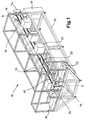
- a system 10 shown in FIG. 1 for processing data carriers 36 has one on a frame 12 mounted pallet conveyor 14 for transport of pallets 16 shown in more detail in FIG. 3.
- the pallet conveyor 14 has an upper rotating conveyor belt 18 and a lower rotating conveyor belt 20 on. On both sides of the conveyor belts 18, 20 are x in the transport direction Processing stations 22 arranged.
- the upper conveyor belt 18 serves the Transport of the pallets 16 equipped with data carriers 36 from the start A to End E of the transport route in the transport direction x.
- the lower conveyor belt 20 transports the empty pallets 16 from the end E of the transport route to their Start A back.
- lowering device 24 will be empty Pallets 16 for their return transport from the upper conveyor belt 18 to the lower one Conveyor belt 20 transferred. In the same way takes place at the beginning A of the transport route the transfer of the pallets 16 from the lower conveyor belt 20 the upper conveyor belt 18 via a lifting device 26.
- FIG. 1 there is a stacking device 28 at the beginning of the transport path A. indicated, in which one or more stacks of data carriers 36 are arranged are. Via ejectors, vacuum suction cups, grippers and similar handling devices the data carriers 36 to be processed are removed from the stacking device 28 and placed on the ready pallets 16. At the end E the Transport route are in turn by not shown in the drawing Handling devices removed the data carrier 36 from the pallets 16 and in a first receptacle 30 stacked. A second receptacle 32 is used, for example, to store reject data carriers.
- the pallets 16 are at the processing stations 22 stopped by conventional means such as stoppers or lifting devices or briefly raised from the upper conveyor belt 18.
- conventional means such as stoppers or lifting devices or briefly raised from the upper conveyor belt 18.
- the processing stations 22 that are not used can be removed from the system 10 removed or even shut down. From the way the system works 10 it is clear that the conveyor system for buffer zones Provides 22 in front of slower working stations Pallets 16 can run onto each other. The system 10 is therefore not on intermittent work bound.
- FIG. 2 shows a pallet 16 resting on the upper conveyor belt 18 in the area a processing station 22 this is in the example shown with a Magnetic read or write head 34 equipped.
- the pallet 16 is vertical a data carrier in to the conveyor level formed by the conveyor belt 18 Form of a magnetic stripe card 36 releasably set. Here lies the level F the magnetic stripe card 36 in the transport direction x. This allows the magnetic stripe card 36 the slot 38 of the magnetic reading or pass head 34 for editing.
- FIG. 3 shows an upper conveyor belt 18 Pallet 16 for releasably accommodating a data carrier, in the present Case a magnetic stripe card 36 with a magnetic stripe 40.
- the magnetic stripe card 36 serve two opposing, from the pallet 16 vertically upstanding brackets 42, 44 facing each other Longitudinal grooves 46, 48, the two ends of a receiving slot correspond.
- the two plane-parallel surfaces 50, 52 are free on both sides accessible and can thus in the processing stations 22 on one or both sides can be processed without the pallet 16 and / or the data carrier have to be repositioned.
Abstract
Description
Die Erfindung betrifft ein Verfahren und eine Anlage zum beidseitigen Bearbeiten von Datenträgern zur Aufnahme und Speicherung von Informationen aller Art in Form von Karten und dgl. flachen Körpern mit zwei zur Bearbeitung vorgesehenen planparallelen Oberflächen, wobei die Karten mittels eines Transportsystems zu einer Bearbeitungsstation geführt, in der Bearbeitungsstation bearbeitet und anschliessend zur nächsten Bearbeitungsstation weitertransportiert werden.The invention relates to a method and a system for double-sided processing of data carriers for the recording and storage of information of all kinds in the form of cards and the like. Flat bodies with two for processing provided plane-parallel surfaces, the cards using a Transport system led to a processing station, in the processing station processed and then transported to the next processing station become.
Datenträger zur Aufnahme und Speicherung von Informationen aller Art in Form von Karten und dgl. flachen Körpern mit zwei zur Bearbeitung vorgesehenen planparallelen Oberflächen sind heute für verschiedenartige Anwendungsbereiche bekannt. Beispiele sind Kreditkarten, Karten zur Zutrittskontrolle und Türöffnung, Zahlkarten für Kantinen, Kaffeeautomaten usw. Informationen können auf der Karte in unterschiedlicher Form aufgebracht sein. So können die Informationen beispielsweise aufgedruckt, geprägt oder in elektronischer Form auf an der Oberfläche der Karten angeordneten Magnetstreifen oder Chips gespeichert sein. Weiter können auf den Karten aus Gründen der Fälschungssicherheit Muster, Hologramme sowie weitere die Fälschungssicherheit erhöhende Elemente über spezielle Druckverfahren aufgetragen sein.Data carriers for recording and storing information of all kinds in Form of cards and the like. Flat bodies with two intended for processing plane-parallel surfaces are today for various types of application known. Examples are credit cards, cards for access control and door opening, payment cards for canteens, coffee machines, etc. Information can be applied to the card in different forms. So can the information is printed, embossed or in electronic form, for example Form on magnetic strips or arranged on the surface of the cards Chips are stored. Further on the cards for reasons of counterfeit security Samples, holograms as well as counterfeit protection increasing elements can be applied using special printing processes.
Zur Bearbeitung derartiger Karten gehört beispielsweise das Laden, Prüfen und Messen der in elektronischer Form gespeicherten Informationen, das beidseitige Beschriften, sowie weitere auf den Kartenoberflächen durchzuführenden Bearbeitungsschritte. Die Bearbeitung eines bestimmten Kartentyps für eine Gruppe von Individuen, beispielsweise für die Mitarbeiter einer Firma, erfolgt heute oft stapelweise bei einzelnen Bearbeitungsmaschinen, wobei ein Kartenstapel nach jeder Bearbeitung für die Durchführung des nachfolgenden Bearbeitungsschrittes zur nächsten Bearbeitungsstation überführt wird. Einzelne Bearbeitungsschritte wie beispielsweise das Laden, Messen und Prüfen von Magnetstreifen und Chips wird heute noch oft von Hand durchgeführt.Loading and checking are part of the processing of such cards and measuring the information stored in electronic form, the bilateral Label, as well as others to be carried out on the card surfaces Processing steps. Editing a specific card type for a group of individuals, for example for the employees of a company today often in batches with individual processing machines, with one Deck of cards after each processing to carry out the following Processing step is transferred to the next processing station. Separate Processing steps such as loading, measuring and testing Magnetic strips and chips are still often carried out by hand.
Es ist auch bereits ein Verfahren vorgeschlagen worden, bei welchem die Karten auf ein Transportband gelegt und unter Bearbeitungsstationen durchgeführt werden. Dieses Verfahren hat den Nachteil, dass die Karten immer nur einseitig bearbeitet werden können. Zur Bearbeitung der zweiten Seite müssen die Karten in jedem Fall von Hand oder über eine Hilfseinrichtung auf dem Band gedreht werden, wodurch sich die Gefahr einer Beschädigung der Karten erhöht.A method has also already been proposed in which the cards placed on a conveyor belt and carried out under processing stations become. This procedure has the disadvantage that the cards are always only one-sided can be edited. To edit the second page, the Cards in any case by hand or via an auxiliary device on the tape are rotated, which increases the risk of damage to the cards.
Der Erfindung liegt deshalb die Aufgabe zugrunde, ein Verfahren sowie eine Anlage der eingangs genannten Art zu schaffen, mit welchen sich die Karten einfacher und bei nur geringer Gefahr einer mechanischen Beschädigung beidseitig bearbeitet werden können.The invention is therefore based on the object, a method and a Create system of the type mentioned, with which the cards easier and with little risk of mechanical damage can be edited on both sides.
Bezüglich des Verfahrens führt zur Lösung der Aufgabe, dass die Datenträger mit beidseits frei zugänglichen Oberflächen lösbar an Paletten festgelegt, die Paletten mit den Datenträgern mittels eines Palettenförderers zu den entlang des Palettenförderers angeordneten Bearbeitungsstationen geführt, in den Bearbeitungsstationen auf den Paletten verbleibend ein- oder beidseitig bearbeitet und nach dem bearbeiten von den Paletten entfernt werden.With regard to the method, the data carrier solves the problem with surfaces freely accessible on both sides, releasably attached to pallets Pallets with the data carriers by means of a pallet conveyor to the along of the pallet conveyor arranged processing stations performed in the processing stations Machined on one or both sides of the pallets and removed from the pallets after processing.
Durch die aufgestellte Datenträgerlage ist eine einfache Bearbeitung von beiden Seiten möglich und durch den während des gesamten Bearbeitungsprozesses in gleicher Lage fixierten Datenträger ist die Gefahr einer mechanischen Beschädigung äusserst gering.Due to the position of the data carrier, it is easy to process both Pages possible and through the entire machining process Data carriers fixed in the same position pose the risk of mechanical Damage is extremely low.
Bevorzugt werden die Paletten einem Förderband aufliegend zu den Bearbeitungsstationen geführt, wobei die Datenträger zweckmässigerweise senkrecht zu der durch das Förderband vorgegebenen Förderebene von den Paletten abragen.The pallets are preferably supported on a conveyor belt to the processing stations performed, the disk usefully vertically to the conveyor level from the pallets specified by the conveyor belt protrude.
Bezüglich der Anlage führt zur erfindungsgemässen Lösung der Aufgabe, dass die Bearbeitungsstationen entlang eines Palettenförderers angeordnet und für den Transport der Karten zu aufeinanderfolgenden Bearbeitungsstationen auf den Palettenförderer aufsetzbare Paletten vorgesehen sind.With regard to the system, the object of the invention is that the processing stations are arranged along a pallet conveyor and for transport of the cards to successive processing stations the pallet conveyor can be placed on pallets.
Bevorzugt weist der Palettenförderer ein Förderband auf. Für den Rücktransport leerer Paletten vom Ende der Transportstrecke zu deren Anfang kann ein zweites Förderband vorgesehen sein.The pallet conveyor preferably has a conveyor belt. For return transportation empty pallets from the end of the transport route to the beginning can be second conveyor belt may be provided.
Eine zur Verwendung mit der erfindungsgemässen Anlage geeignete Palette ist mit einem Aufnahmeorgan zum lösbaren Festlegen der Datenträger unter Beibehaltung beidseits zugänglicher Oberflächen ausgestattet. Das Aufnahmeorgan kann beispielsweise ein Schlitz in der Palette sein. Bei einer zweckmässigen Ausgestaltungsform weist das Aufnahmeorgan zwei einander gegenüberstehende Halterungen mit Nuten zum Einschieben des Datenträgers auf.A pallet suitable for use with the system according to the invention is with a receiving element for releasably fixing the data carrier while maintaining it surfaces accessible on both sides. The receiving body can be a slot in the pallet, for example. With an expedient In one embodiment, the receiving member has two opposite one another Brackets with grooves for inserting the data carrier.
Weitere Vorteile , Merkmale und Einzelheiten der Erfindung ergeben sich aus der nachfolgenden Beschreibung bevorzugter Ausführungsbeispiele sowie anhand der Zeichnung; diese zeigt schematisch in
- Fig. 1
- eine Schrägsicht auf eine Anlage zum beidseitigen Bearbeiten von Datenträgern;
- Fig.2
- einen Schnitt durch einen Teil der Anlage von Fig. 1 gemäss deren Linie I-I;
- Fig. 3
- eine Schrägsicht auf eine Palette mit eingesetzter Magnetstreifenkarte.
- Fig. 1
- an oblique view of a system for double-sided processing of data carriers;
- Fig. 2
- a section through part of the system of Figure 1 along the line II.
- Fig. 3
- an oblique view of a pallet with a magnetic stripe card inserted.
Eine Fig. 1 gezeigte Anlage 10 zum Bearbeiten von Datenträgern 36 weist einen
auf einem Rahmen 12 montierten Palettenförderer 14 für den Transport
von in Fig. 3 näher dargestellten Paletten 16 auf. Der Palettenförderer 14 weist
ein oberes umlaufendes Förderband 18 und ein unteres umlaufendes Förderband
20 auf. Beidseits der Förderbänder 18, 20 sind in Transportrichtung x
Bearbeitungsstationen 22 angeordnet. Das obere Förderband 18 dient dem
Transport der mit Datenträgern 36 bestückten Paletten 16 vom Anfang A zum
Ende E der Transportstrecke in Transportrichtung x. Das untere Förderband 20
transportiert die leeren Paletten 16 vom Ende E der Transportstrecke zu deren
Anfang A zurück. Über eine im einzelnen nicht dargestellte, am Ende E des
Palettenförderers 14 angeordnete Absenkeinrichtung 24 werden die leeren
Paletten 16 für deren Rücktransport vom oberen Förderband 18 auf das untere
Förderband 20 überführt. In gleicher Weise erfolgt am Anfang A der Transportstrecke
die Überführung der Paletten 16 vom unteren Förderband 20 auf
das obere Förderband 18 über eine Hebeinrichtung 26.A
In Fig. 1 ist weiter am Anfang der Transportstrecke A eine Stapeleinrichtung 28
angedeutet, in der eine oder mehrere Stapel von Datenträgern 36 angeordnet
sind. Über Ausstosser, Vakuumsauger, Greifer und dgl. Handlingeinrichtungen
werden die zu bearbeitenden Datenträger 36 der Stapeleinrichtung 28 entnommen
und auf die bereitstehenden Paletten 16 aufgesetzt. Am Ende E der
Transportstrecke werden wiederum durch in der Zeichnung nicht dargestellte
Handlingeinrichtungen die Datenträger 36 von den Paletten 16 entfernt und in
einem ersten Aufnahmebehälter 30 gestapelt. Ein zweiter Aufnahmebehälter 32
dient beispielsweise zur Aufnahme von Ausschuss-Datenträgern.In FIG. 1 there is a stacking
Auf ihrem Transportweg werden die Paletten 16 bei den Bearbeitungsstationen
22 mit herkömmlichen Mitteln wie Stopper oder Hebevorrichtungen angehalten
bzw. kurzzeitig vom oberen Förderband 18 angehoben. Bei der Bearbeitung
von Datenträgern 36 sind nicht immer alle Bearbeitungsstationen 22 erforderlich.
Die nicht verwendeten Bearbeitungsstationen 22 können aus der Anlage
10 entfernt oder auch nur stillgelegt werden. Aus der Funktionsweise der Anlage
10 geht ohne weiteres hervor, dass das Fördersystem Pufferzonen zur
Verfügung stellt, indem vor langsamer arbeitenden Bearbeitungsstationen 22
Paletten 16 aufeinander auflaufen können. Die Anlage 10 ist somit nicht an ein
taktweises Arbeiten gebunden.On their transport route, the
Fig. 2 zeigt eine auf dem oberen Förderband 18 aufliegende Palette 16 im Bereich
einer Bearbeitungsstation 22 diese ist im dargestellten Beispiel mit einem
Magnetlese- bzw. schreibkopf 34 ausgestattet. Auf der Palette 16 ist senkrecht
zu der durch das Förderband 18 gebildeten Förderebene ein Datenträger in
Form einer Magnetstreifenkarte 36 lösbar festgelegt. Hierbei liegt die Ebene F
der Magnetstreifenkarte 36 in der Transportrichtung x. Dadurch kann die Magnetstreifenkarte
36 ohne Positionsänderung den Schlitz 38 des Magnetlese- bzw.
schreibkopfs 34 zur Bearbeitung passieren.2 shows a
Die in Fig. 3 dargestellte Anordnung zeigt eine dem oberen Förderband 18 aufliegende
Palette 16 zur lösbaren Aufnahme eines Datenträgers, im vorliegenden
Fall eine Magnetstreifenkarte 36 mit einem Magnetstreifen 40. Zur Aufnahme
der Magnetstreifenkarte 36 dienen zwei einander gegenüberliegende,
von der Palette 16 senkrecht aufragende Halterungen 42, 44 mit einander zugewandten
Längsnuten 46, 48, die den zwei Enden eines Aufnahmeschlitzes
entsprechen. Die beiden planparallelen Oberflächen 50, 52 sind beidseits frei
zugänglich und können damit in den Bearbeitungsstationen 22 ein- oder beidseitig
bearbeitet werden, ohne dass die Palette 16 und/oder der Datenträger
neu positioniert werden müssen.The arrangement shown in FIG. 3 shows an
Claims (9)
dadurch gekennzeichnet, dass
die Datenträger (36) mit beidseits zugänglichen Oberflächen (50, 52) lösbar an Paletten (16) festgelegt, die Paletten (16) mit den Datenträgern (36) mittels eines Palettenförderers (14) zu den entlang des Palettenförderers angeordneten Bearbeitungsstationen (22) geführt, in den Bearbeitungsstationen (22) auf den Paletten (16) verbleibend ein- oder beidseitig bearbeitet und nach dem Bearbeiten von den Paletten (16) entfernt werden.Method for processing data carriers (36) on both sides for receiving and storing information of all kinds in the form of cards and the like Processing station (22) guided, processed in the processing station and then transported to the next processing station,
characterized in that
the data carriers (36) with surfaces (50, 52) accessible on both sides are releasably attached to pallets (16), the pallets (16) with the data carriers (36) are guided by a pallet conveyor (14) to the processing stations (22) arranged along the pallet conveyor , in the processing stations (22) on the pallets (16) remaining processed on one or both sides and removed from the pallets (16) after processing.
dadurch gekennzeichnet, dass
die Bearbeitungsstationen (22) entlang eines Palettenförderers (14) angeordnet und für den Transport der Datenträger (36) zu aufeinanderfolgenden Bearbeitungsstationen auf den Palettenförderer (14) aufsetzbare Paletten vorgesehen sind.System for double-sided processing of data carriers (36) for receiving and storing information of all kinds in the form of cards and the like Processing station (22) guided, processed in the processing station and then transported to the next processing station,
characterized in that
the processing stations (22) are arranged along a pallet conveyor (14) and pallets which can be placed on the pallet conveyor (14) for the transport of the data carriers (36) to successive processing stations are provided.
dadurch gekennzeichnet, dass
die Palette (16) mit einem Aufnahmeorgan zum lösbaren Festlegen der Datenträger (36) unter Beibehaltung beidseits zugänglicher Oberflächen (50, 52) ausgestattet ist.Pallet for temporary recording and for the transport of data carriers (36) for recording and storing information of all kinds in the form of cards and the like. Flat bodies with two plane-parallel surfaces (50, 52) provided for processing,
characterized in that
the pallet (16) is equipped with a receiving element for releasably fixing the data carrier (36) while maintaining surfaces (50, 52) accessible from both sides.
Priority Applications (1)
| Application Number | Priority Date | Filing Date | Title |
|---|---|---|---|
| EP99810185A EP1033671A1 (en) | 1999-03-04 | 1999-03-04 | Method and device for treating data carriers |
Applications Claiming Priority (1)
| Application Number | Priority Date | Filing Date | Title |
|---|---|---|---|
| EP99810185A EP1033671A1 (en) | 1999-03-04 | 1999-03-04 | Method and device for treating data carriers |
Publications (1)
| Publication Number | Publication Date |
|---|---|
| EP1033671A1 true EP1033671A1 (en) | 2000-09-06 |
Family
ID=8242706
Family Applications (1)
| Application Number | Title | Priority Date | Filing Date |
|---|---|---|---|
| EP99810185A Withdrawn EP1033671A1 (en) | 1999-03-04 | 1999-03-04 | Method and device for treating data carriers |
Country Status (1)
| Country | Link |
|---|---|
| EP (1) | EP1033671A1 (en) |
Cited By (2)
| Publication number | Priority date | Publication date | Assignee | Title |
|---|---|---|---|---|
| WO2004095381A2 (en) * | 2003-04-19 | 2004-11-04 | Böwe Cardtec GmbH | Laser inscription station for credit cards |
| DE10218252B4 (en) * | 2001-05-02 | 2014-04-30 | Ruhlamat Gmbh | Method and device for applying security measures to passbooks |
Citations (3)
| Publication number | Priority date | Publication date | Assignee | Title |
|---|---|---|---|---|
| US4686898A (en) * | 1986-01-21 | 1987-08-18 | National Business Systems, Inc. | Credit card embossing system |
| US4692041A (en) * | 1983-12-27 | 1987-09-08 | Mannesmann Kienzle Gmbh | Document encoder |
| US5558449A (en) * | 1994-04-15 | 1996-09-24 | Gemplus Card International | Simultaneous two-face printing machine |
-
1999
- 1999-03-04 EP EP99810185A patent/EP1033671A1/en not_active Withdrawn
Patent Citations (3)
| Publication number | Priority date | Publication date | Assignee | Title |
|---|---|---|---|---|
| US4692041A (en) * | 1983-12-27 | 1987-09-08 | Mannesmann Kienzle Gmbh | Document encoder |
| US4686898A (en) * | 1986-01-21 | 1987-08-18 | National Business Systems, Inc. | Credit card embossing system |
| US5558449A (en) * | 1994-04-15 | 1996-09-24 | Gemplus Card International | Simultaneous two-face printing machine |
Cited By (5)
| Publication number | Priority date | Publication date | Assignee | Title |
|---|---|---|---|---|
| DE10218252B4 (en) * | 2001-05-02 | 2014-04-30 | Ruhlamat Gmbh | Method and device for applying security measures to passbooks |
| WO2004095381A2 (en) * | 2003-04-19 | 2004-11-04 | Böwe Cardtec GmbH | Laser inscription station for credit cards |
| WO2004095381A3 (en) * | 2003-04-19 | 2005-01-06 | Boewe Cardtec Gmbh | Laser inscription station for credit cards |
| JP2006524149A (en) * | 2003-04-19 | 2006-10-26 | ベーヴエ・カルトテク・ゲゼルシヤフト・ミツト・ベシユレンクテル・ハフツング | Laser writing station for credit cards |
| US7800015B2 (en) | 2003-04-19 | 2010-09-21 | Böwe Cardtec GmbH | Laser inscribing station for credit cards |
Similar Documents
| Publication | Publication Date | Title |
|---|---|---|
| DE19709562C2 (en) | System for processing chip and / or magnetic stripe cards | |
| DE202016009054U1 (en) | Card printing mechanism with card return path | |
| EP0863483B1 (en) | Arrangement for processing chip and/or magnetic cards | |
| DE112018005784T5 (en) | Freight identification code, things on which it is attached and the robot gripper that can be used for this | |
| DE3528199C2 (en) | ||
| EP3653395A1 (en) | Device and method for producing a data card for a book-style identification, value or security document, system and method for the production of a book-style identification, value or security document and data card for an identification, value or security document | |
| EP1033671A1 (en) | Method and device for treating data carriers | |
| EP2706484A2 (en) | Card mass storage, transport and and memory device and method of sorting memory cards | |
| DE4218429C2 (en) | Methods of identifying, labeling and targeting goods | |
| WO2018115075A2 (en) | Method for identifying workpieces, associated manufacturing station and associated re-fitting method | |
| EP2462543B1 (en) | Personalizing card-shaped data carriers | |
| DE102011118190A1 (en) | Device for combining subscriber identification module card and card holder in application region, has processing station, measuring station, and/or intermediate storage units arranged in area of manipulator | |
| EP0597135A1 (en) | Device for reading and writing on magnetic cards | |
| EP0955172B1 (en) | Method and cassette for printing on a booklet-type object | |
| DE3704414C2 (en) | ||
| DE3538720A1 (en) | Machining station | |
| DE102016217045A1 (en) | Device for laminating a material sheet booklet | |
| EP3362193B1 (en) | Device and method for sorting booklet-type valuable documents | |
| WO2009095474A1 (en) | Laser labeling device | |
| WO2000005682A1 (en) | Machine-readable identity card | |
| DE3608068C2 (en) | Device for transporting documents of different widths | |
| DE4008965C2 (en) | Device for coding and labeling data carrier cards | |
| DE4421787C1 (en) | Process and apparatus for separating, sorting and depositing stacks of veneers | |
| DE102004053027B4 (en) | Method and device for providing cards for automated card shipping | |
| DE69728903T2 (en) | METHOD FOR PERSONALIZING FLAT CARRIERS |
Legal Events
| Date | Code | Title | Description |
|---|---|---|---|
| PUAI | Public reference made under article 153(3) epc to a published international application that has entered the european phase |
Free format text: ORIGINAL CODE: 0009012 |
|
| AK | Designated contracting states |
Kind code of ref document: A1 Designated state(s): CH DE FR GB IT LI |
|
| AX | Request for extension of the european patent |
Free format text: AL;LT;LV;MK;RO;SI |
|
| 17P | Request for examination filed |
Effective date: 20010213 |
|
| AKX | Designation fees paid |
Free format text: CH DE FR GB IT LI |
|
| STAA | Information on the status of an ep patent application or granted ep patent |
Free format text: STATUS: THE APPLICATION IS DEEMED TO BE WITHDRAWN |
|
| 18D | Application deemed to be withdrawn |
Effective date: 20031001 |