EP1033538A2 - Cooking apparatus with temperature sensor - Google Patents
Cooking apparatus with temperature sensor Download PDFInfo
- Publication number
- EP1033538A2 EP1033538A2 EP00104087A EP00104087A EP1033538A2 EP 1033538 A2 EP1033538 A2 EP 1033538A2 EP 00104087 A EP00104087 A EP 00104087A EP 00104087 A EP00104087 A EP 00104087A EP 1033538 A2 EP1033538 A2 EP 1033538A2
- Authority
- EP
- European Patent Office
- Prior art keywords
- cooking
- mouth
- sensor module
- appliance according
- suction device
- Prior art date
- Legal status (The legal status is an assumption and is not a legal conclusion. Google has not performed a legal analysis and makes no representation as to the accuracy of the status listed.)
- Withdrawn
Links
Images

Classifications
-
- F—MECHANICAL ENGINEERING; LIGHTING; HEATING; WEAPONS; BLASTING
- F24—HEATING; RANGES; VENTILATING
- F24C—DOMESTIC STOVES OR RANGES ; DETAILS OF DOMESTIC STOVES OR RANGES, OF GENERAL APPLICATION
- F24C15/00—Details
- F24C15/20—Removing cooking fumes
- F24C15/2007—Removing cooking fumes from oven cavities
-
- F—MECHANICAL ENGINEERING; LIGHTING; HEATING; WEAPONS; BLASTING
- F24—HEATING; RANGES; VENTILATING
- F24C—DOMESTIC STOVES OR RANGES ; DETAILS OF DOMESTIC STOVES OR RANGES, OF GENERAL APPLICATION
- F24C15/00—Details
- F24C15/006—Arrangements for circulation of cooling air
-
- F—MECHANICAL ENGINEERING; LIGHTING; HEATING; WEAPONS; BLASTING
- F24—HEATING; RANGES; VENTILATING
- F24C—DOMESTIC STOVES OR RANGES ; DETAILS OF DOMESTIC STOVES OR RANGES, OF GENERAL APPLICATION
- F24C7/00—Stoves or ranges heated by electric energy
- F24C7/08—Arrangement or mounting of control or safety devices
-
- Y—GENERAL TAGGING OF NEW TECHNOLOGICAL DEVELOPMENTS; GENERAL TAGGING OF CROSS-SECTIONAL TECHNOLOGIES SPANNING OVER SEVERAL SECTIONS OF THE IPC; TECHNICAL SUBJECTS COVERED BY FORMER USPC CROSS-REFERENCE ART COLLECTIONS [XRACs] AND DIGESTS
- Y10—TECHNICAL SUBJECTS COVERED BY FORMER USPC
- Y10S—TECHNICAL SUBJECTS COVERED BY FORMER USPC CROSS-REFERENCE ART COLLECTIONS [XRACs] AND DIGESTS
- Y10S99/00—Foods and beverages: apparatus
- Y10S99/14—Induction heating
Definitions
- the present invention relates to a cooking appliance according to the preamble of Claim 1.
- Generic cooking devices allow the progress of the cooking process within to monitor a cooking space using a non-contact temperature measurement.
- the temperature of a measuring surface inside the cooking chamber is recorded, that is for example the surface of the prepared food or a wall of the Cooking appliances.
- the use of an infrared sensor is known but must be protected against pollution and excessive heating, in order to ensure accuracy.
- the infrared sensor from a around the cooling air flow. The problem is that it becomes a simultaneous cooling of the overnight measuring surface and thus to one Impairment of the food to be cooked and falsification of the measurement result can.
- JP 08021631 A describes a microwave oven in which cool air is blown by a fan placed in the oven and heated air is removed from the oven.
- the Microwave oven is with light sensors and bimetallic thermocouples arranged in front of them equipped, which are cooled by the fan.
- the heating element or one Temperature control device performs the deformation resulting from the heating the bimetal thermocouples to a switching pulse in the light sensors and ultimately to turn off the microwave oven.
- this arrangement allows no statement about the progress of the cooking process. There is also an influence of the food is not excluded by the ventilation.
- the invention has for its object to develop a cooking device, the one simple and reliable monitoring of the cooking process with simultaneous Maintenance of the quality of the cooking result allowed.
- the solution according to the invention provides a suction device for extracting air out of the cooking appliance.
- Extraction means any device that actively supports the escape of air from the cooking space. This allows targeted on to act on the cooling air flow.
- the flow thus moves roughly along an imaginary straight line Connection of a mouth on the cooking chamber side of a feed device and one mouth of the suction device on the cooking chamber side. This will be a spacing guarantees this connecting line against the measuring surface, so the cooling Airflow does not affect the measuring surface. This influences the measurement result and Food excluded.
- a deeper penetration of the cooling air flow into the cooking space can also thereby be avoided that the mouth of the Feeding device on the same wall of the cooking space as the cooking space side Mouth of the suction device is arranged. This applies in particular if the Mouth end of the feed device next to the cooking chamber side Mouth of the suction device is arranged. This effect is enhanced when the mouth of the feeder on the cooking chamber side, the mouth of the cooking chamber Suction device surrounds or vice versa. An introduction to the cooling air flow in the cooking space is avoided entirely if the feeder on the cooking chamber side opens into the suction device.
- the cooking space 1 has a heatable cooking space 1, which faces outwards is bounded on all sides by walls 3, 5, 7 or a door 9.
- the cooking space 1 is used for Picking up a food to be cooked 11.
- An air supply device 13 is provided in the housing of the cooking appliance. This has an air duct 15 which at one end at an opening 17 through a Opening of the wall 5 opens into the cooking space 1 and one at its other end Fresh air supply opening 19 has.
- a sensor module 21 in the air duct 15 intended. It is through the mouth 17 of the feed device 13 to a Measuring surface 23 directed to the surface of the food 11 to be cooked. The measuring direction is there indicated by a dashed line 18.
- the cooking device also has a suction device 25, which on the Cooking space 1 facing away from the ceiling wall 7 is mounted.
- the suction device 25 has an air duct 27, which at one end at a mouth 29 in the Cooking chamber 1 opens and at its other end a blow-out opening 31 of the Has housing.
- the suction device 25 also has a fan 33, which on the air duct 27 is connected.
- the cooking appliance works as follows. Detected during the cooking process the sensor 21 radiates from the measuring surface 23 of the food 11 to be cooked Infrared radiation and forwards the recorded values to a subsequent evaluation Evaluation electronics, not shown, continue to the cooking process according to the settings made by an operator in a manner known per se Taxes.
- the negative pressure that arises in the cooking space 1 leads to an afterflow of air from the fresh air supply opening 19 via the air duct 15 of the supply device 13.
- the air flows past the sensor module 21 through the mouth 17 into the Cooking space 1.
- Fig. 2 shows a detail of a second embodiment.
- the suction device 25 is designed as a vapor extraction. Your Mouth 29 on the cooking chamber side is therefore covered with a vapor filter 35.
- the Feed device 13 is arranged so that its air duct 15 in the Vapor filter 35 opens.
- the cooling air sucked in by the supply device 13 can be used in a manner known per se for cooling electrical components Cooking appliances 1 can be used.
- the mouth 17 of the feed device 13 is thus surrounded by the mouth 29 of the suction device 25. In this case the imaginary straight-line connection between the two in the oven side Surface of the vapor filter 35.
- the sensor module 21 is inside the Feed device 13 arranged in the vapor filter 35.
- the cross-sectional area of the mouth 29 of the suction device 25 corresponds approximately to that Area of the vapor filter 35. It is thus significantly larger than the cross-sectional area of the feed device 13 at its mouth 17 on the cooking space is advantageous moreover, when the flow velocity at the mouth 29 of the Suction device 25 is larger than that at the mouth 17 of the Feeding device 13. As a result, more air is supplied via the suction device 25 aspirated when the cooking chamber 1 is fed via the feed device 13. The cooling air blown through the mouth 17 in the ceiling area then penetrates into the Cooking chamber on and XXX forward to food 11, but is immediately switched on again of the fan 33 is sucked off.
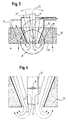
- Fig. 3 shows an advantageous embodiment of the mouth 17 of the feed device 13 according to the embodiment of FIG. 2, according to a first Embodiment.
- the air duct 15 of the feed device 13 tapers in this design in its end area on the cooking chamber side towards the mouth 17 and is in the process formed by the vapor filter 35.
- the end face of the sensor module 21 is 22 positioned directly at the mouth 17.
- the sensor module 21 is there - as if by one Arrow 24 and an alternative position 21 'indicated - pivotally mounted.
- the tapering accelerates the air flow towards the mouth 17. Thereby the cooling and dirt-repellent effect of the air flow is enhanced without to increase the volume flow.
- the pivotability of the sensor module 21 enables the front side 22 to be opened to direct different areas of the cooking space 1 and a precise adjustment of the Make sensor modules 21 on the respective measuring surface 23 to be monitored. This allows the sensor module 21 to ensure optimum measurement accuracy for example, different insertion heights of the food to be adjusted.
- the Freedom of movement of the sensor module 21 is due to the conical shape of the Air channel 15 in the vapor filter 35 favors.
- FIG. 4 shows an advantageous embodiment of a sensor module on an enlarged scale Scale in an arrangement according to a fourth embodiment.
- the sensor module 21 arranged in the mouth area of the feed device 13 has an aperture 37 on its front side 22. Viewed from the cooking space 1 a lens 39 is arranged behind it. Are between aperture 37 and lens 39 Openings 41 are provided laterally in the sensor module 21.
- the cooling air flows partially out of the air duct 15 through the lateral openings 41 in the sensor module 21 and occurs at the Aperture opening 37 in the direction of the cooking space 1 again. This means one additional protection of the lens 39 against dirt and overheating.
- the pivoting of the sensor module could on individual parts, such as a Lens optics, be limited.
- an introduction of one could Airflow into the cooking space can be completely avoided.
- the cooling air would come after flowing past the sensor module directly from the suction device without getting into the cooking space.
- the air supply could have a fan that actively air into the cooking device brings in.
Abstract
Description
Die vorliegende Erfindung betrifft ein Gargerät nach dem Oberbegriff des
Patentanspruches 1.The present invention relates to a cooking appliance according to the preamble of
Gattungsgemäße Gargeräte gestatten, den Fortschritt des Garprozesses innerhalb eines Garraumes anhand einer berührungslosen Temperaturmessung zu überwachen. Dabei wird die Temperatur einer Meßfläche innerhalb des Garraums erfaßt, also beispielsweise der Oberfläche des zubereiteten Lebensmittels oder einer Wand des Gargeräts. Zu diesem Zweck ist die Verwendung eines Infrarotsensors bekannt, der allerdings vor Verschmutzung und übermäßiger Erwärmung geschützt werden muß, um dem Genauigkeit gewährleisten zu können. Dazu wird der Infrarotsensor von einer kühlenden Luftströmung umspült. Problematisch ist, daß es dabei zu einer gleichzeitigen Abkühlung der übernachten Meßfläche und somit zu einer Beeinträchtigung des Gargutes und einer Verfälschung des Meßergebnisses kommen kann.Generic cooking devices allow the progress of the cooking process within to monitor a cooking space using a non-contact temperature measurement. The temperature of a measuring surface inside the cooking chamber is recorded, that is for example the surface of the prepared food or a wall of the Cooking appliances. For this purpose, the use of an infrared sensor is known but must be protected against pollution and excessive heating, in order to ensure accuracy. For this purpose, the infrared sensor from a around the cooling air flow. The problem is that it becomes a simultaneous cooling of the overnight measuring surface and thus to one Impairment of the food to be cooked and falsification of the measurement result can.
JP 08021631 A beschreibt einen Mikrowellenofen in dem durch einen Lüfter kühle Luft in den Ofen eingebracht und erwärmte Luft aus dem Ofen entfernt wird. Der Mikrowellenofen ist mit Lichtsensoren und vor diesen angeordneten Bimetall-Thermoelementen ausgestattet, welche durch den Lüfter gekühlt werden. Bei Betriebsstörungen des Lüfters, des Heizelementes oder einer Temperaturregeleinrichtung führt die aus der Erwärmung resultierende Verformung der Bimetall-Thermoelemente zu einem Schaltimpuls in den Lichtsensoren und letztlich zu einem Abschalten des Mikrowellenofens. Allerdings gestattet diese Anordnung keinerlei Aussage über den Fortschritt des Garprozesses. Auch ist eine Beeinflussung des Gargutes durch die Belüftung nicht ausgeschlossen.JP 08021631 A describes a microwave oven in which cool air is blown by a fan placed in the oven and heated air is removed from the oven. The Microwave oven is with light sensors and bimetallic thermocouples arranged in front of them equipped, which are cooled by the fan. At Malfunctions of the fan, the heating element or one Temperature control device performs the deformation resulting from the heating the bimetal thermocouples to a switching pulse in the light sensors and ultimately to turn off the microwave oven. However, this arrangement allows no statement about the progress of the cooking process. There is also an influence of the food is not excluded by the ventilation.
In "Thermopile-IR-Sensormodul zur berührungslosen Temperaturmessung in Haushaltsgeräten", J. Schiefendecker et al., Wiss. Z. techn. Univers. Dresden 43 (1994) Heft 6, S. 41 - 44 ist die Anordnung eines Infrarot-Sensormodules in der Deckenwand eines Mikrowellengarraums beschrieben. Dabei wird eine Kühlluftströmung im wesentlichen parallel zur Deckenwand geführt. Sie strömt dabei an einer mit einem Schutzfilter ausgestatteten Stirnwand des Infrarotsensormoduls vorbei. Nachteilig ist hierbei jedoch, daß die Luftströmung zu Verwirbelungen im Bereich des Schutzfilters führt und dadurch zum Eintrag von Schmutzpartikeln beiträgt. Außerdem ist diese Art der Luftführung technisch relativ aufwendig.In "Thermopile IR sensor module for non-contact temperature measurement in Household Appliances ", J. Schiefendecker et al., Wiss. Z. techn. Univers. Dresden 43 (1994) Issue 6, pp. 41 - 44 is the arrangement of an infrared sensor module in the Ceiling wall of a microwave oven described. Doing so Cooling air flow guided essentially parallel to the ceiling wall. It flows here on a front wall of the infrared sensor module equipped with a protective filter past. The disadvantage here, however, is that the air flow to swirl in Area of the protective filter and thereby contributes to the entry of dirt particles. In addition, this type of air flow is technically relatively complex.
Der Erfindung liegt die Aufgabe zugrunde, ein Gargerät zu entwickeln, das eine einfache und zuverlässige Überwachung des Garprozesses bei gleichzeitiger Erhaltung der Qualität des Garergebnisses gestattet.The invention has for its object to develop a cooking device, the one simple and reliable monitoring of the cooking process with simultaneous Maintenance of the quality of the cooking result allowed.
Diese Aufgabe ist hier mit einem Gargerät mit den Merkmalen des Anspruches 1
gelöst. Vorteilhafte Ausgestaltungen sind den Unteransprüchen entnehmbar.This task is here with a cooking appliance with the features of
Die erfindungsgemäße Lösung sieht eine Absaugeinrichtung zum Absaugen von Luft aus dem Gargerät vor. Unter Absaugeinrichtung wird jede Einrichtung verstanden, die einen Austritt von Luft aus dem Garraum aktiv unterstützt. Dies ermöglicht, gezielt auf die kühlende Luftströmung einzuwirken.The solution according to the invention provides a suction device for extracting air out of the cooking appliance. Extraction means any device that actively supports the escape of air from the cooking space. This allows targeted on to act on the cooling air flow.
Die Strömung bewegt sich dadurch in etwa entlang einer gedachten geradlinigen Verbindung einer garraumseitigen Mündung einer Zuführungseinrichtung und einer garraumseitigen Mündung der Absaugeinrichtung . Wird dabei eine Beabstandung dieser Verbindungslinie gegen die Meßfläche gewährleistet, so erreicht der kühlende Luftstrom die Meßfläche nicht. Dadurch ist eine Beeinflussung von Meßergebnis und Gargut ausgeschlossen.The flow thus moves roughly along an imaginary straight line Connection of a mouth on the cooking chamber side of a feed device and one mouth of the suction device on the cooking chamber side. This will be a spacing guarantees this connecting line against the measuring surface, so the cooling Airflow does not affect the measuring surface. This influences the measurement result and Food excluded.
Ein tieferes Eindringen des kühlenden Luftstromes in den Garraum kann außerdem dadurch vermieden werden, daß die garraumseitige Mündung der Zuführungseinrichtung an derselben Wand des Garraums wie die garraumseitige Mündung der Absaugeinrichtung angeordnet ist. Dies gilt insbesondere, wenn die garraumseitige Mündung der Zuführungseinrichtung neben der garraumseitigen Mündung der Absaugeinrichtung angeordnet ist. Dieser Effekt wird verstärkt, wenn die garraumseitige Mündung der Zuführungseinrichtung die garraumseitige Mündung der Absaugeinrichtung umgibt oder umgekehrt. Eine Einleitung des kühlenden Luftstromes in den Garraum wird gänzlich vermieden, wenn die Zuführungseinrichtung garraumseitig in die Absaugeinrichtung mündet. A deeper penetration of the cooling air flow into the cooking space can also thereby be avoided that the mouth of the Feeding device on the same wall of the cooking space as the cooking space side Mouth of the suction device is arranged. This applies in particular if the Mouth end of the feed device next to the cooking chamber side Mouth of the suction device is arranged. This effect is enhanced when the mouth of the feeder on the cooking chamber side, the mouth of the cooking chamber Suction device surrounds or vice versa. An introduction to the cooling air flow in the cooking space is avoided entirely if the feeder on the cooking chamber side opens into the suction device.
Eine besonders gute Kühlung ergibt sich, wenn das Sensormodul zumindest teilweise innerhalb der Zuführungseinrichtung angeordnet ist oder zumindest nahe der garraumseitigen Mündung der Zuführungseinrichtung im Garraum vorgesehen ist.Particularly good cooling results when the sensor module is at least partially is arranged within the feed device or at least close to the mouth of the feed device in the cooking space is provided on the cooking space side.
Sind die Querschnittsfläche der Absaugeinrichtung und die Strömungsgeschwindigkeit (meßbar als Staudruck) an ihrer garraumseitigen Mündung größer als die Querschnittsfläche der Zuführungseinrichtung an ihrer garraumseitigen Mündung, so ermöglicht dies eine verbesserte Saugwirkung, da der abführbare Volumenstrom tendenziell größer als der zugeführte Volumenstrom ist.Are the cross-sectional area of the suction device and the flow rate (measurable as dynamic pressure) larger than that at its mouth on the cooking space side Cross-sectional area of the feed device at its mouth on the cooking space, see above this enables an improved suction effect, since the removable volume flow tends to be larger than the volume flow supplied.
Die Erfindung wird im folgenden anhand von Ausführungsbeispielen unter Bezug auf die begleitenden Zeichnungen beschrieben, wobei die nachfolgenden Ausführungen lediglich beispielhafter Natur sind. Die Zeichnungen zeigen:
- Fig. 1
- einen Querschnitt durch eine erste Ausführungsform eines Gargeräts gemäß einem ersten Ausführungsbeispiel,
- Fig. 2
- einen Längsschnitt durch einen Wandausschnitt gemäß einem zweiten Ausführungsbeispiel,
- Fig. 3
- einen Längsschnitt durch eine vorteilhafte Ausgestaltung einer Mündung der Zuführungseinrichtung gemäß einem dritten Ausführungsbeispiel und
- Fig. 4
- einen Längsschnitt durch eine vorteilhafte Ausgestaltung des Sensormoduls entsprechend Detail B von Fig. 3 gemäß einem vierten Ausführungsbeispiel.
- Fig. 1
- 3 shows a cross section through a first embodiment of a cooking appliance according to a first exemplary embodiment,
- Fig. 2
- 2 shows a longitudinal section through a wall cutout according to a second exemplary embodiment,
- Fig. 3
- a longitudinal section through an advantageous embodiment of a mouth of the feed device according to a third embodiment and
- Fig. 4
- a longitudinal section through an advantageous embodiment of the sensor module according to detail B of FIG. 3 according to a fourth embodiment.
Das Gargerät nach Fig. 1 besitzt einen beheizbaren Garraum 1, der nach außen
allseitig von Wänden 3, 5, 7 bzw. einer Tür 9 begrenzt wird. Der Garraum 1 dient der
Aufnahme eines zu garenden Gargutes 11.1 has a
Im Gehäuse des Gargerätes ist eine Luft-Zuführungseinrichtung 13 vorgesehen. Diese
besitzt einen Luftkanal 15, der an seinem einen Ende an einer Mündung 17 durch eine
Öffnung der Wand 5 in den Garraum 1 mündet und an seinem anderen Ende eine
Frischluftzufuhröffnung 19 aufweist. An
Im Bereich der Mündungsöffnung 17 ist ein Sensormodul 21 im Luftkanal 15
vorgesehen. Es ist durch die Mündung 17 der Zuführungseinrichtung 13 auf eine
Meßfläche 23 auf der Oberfläche des Gargutes 11 gerichtet. Die Meßrichtung ist dabei
durch eine gestrichelte Linie 18 angedeutet.In the area of the mouth opening 17 there is a
Das Gargerät weist außerdem eine Absaugeinrichtung 25 auf, welche auf der dem
Garraum 1 abgewandten Seite der Deckenwand 7 montiert ist. Die Absaugeinrichtung
25 besitzt einen Luftkanal 27, der an einem Ende an einer Mündung 29 in den
Garraum 1 mündet und an seinem anderen Ende eine Ausblasöffnung 31 des
Gehäuses besitzt. Die Absaugeinrichtung 25 besitzt außerdem einen Lüfter 33, der an
den Luftkanal 27 angeschlossen ist.The cooking device also has a
Die Funktionsweise des Gargerätes ist wie folgt. Während des Garvorganges erfaßt
der Sensor 21 die von der Meßfläche 23 des Gargutes 11 abgestrahlte
Infrarotstrahlung und leitet die erfaßten Werte zur nachfolgenden Auswertung an eine
nicht dargestellte Auswerteelektronik weiter, um den Garvorgang entsprechend den
von einr Bedienperson vorgenommenen Einstellungen in an sich bekannter Weise zu
steuern.The cooking appliance works as follows. Detected during the cooking process
the
Während dessen transportiert der Lüfter 33 von der Mündung 29 aus Luft aus dem
Garraum 1 durch den Luftkanal 27 zur Ausblasöffnung 31. Die mit Pfeilen versehen
Linien in den Zeichnungen deuten den Strömungsverlauf der Luft an.During this, the
Der im Garraum 1 entstehende Unterdruck führt zu einem Nachströmen von Luft von
der Frischluftzufuhröffnung 19 über den Luftkanal 15 der Zuführungseinrichtung 13.
Die Luft strömt dabei am Sensormodul 21 vorbei durch die Mündung 17 in den
Garraum 1.The negative pressure that arises in the
Durch den Sog der Absaugeinrichtung 25 wird die in den Garraum 1 eintretende Luft in
Richtung auf die Mündung 29 der Absaugeinrichtung 25 gelenkt. Auf ihrem Weg durch
den Garraum 1 folgt sie deshalb in etwa der punktiert dargestellten gedachten
Verbindung 20 zwischen der Mündung 17 der Zuführungseinrichtung 13 und der
Mündung 29 der Absaugeinrichtung 25. Der Luftstrom wird also mittels der
Absaugeinrichtung 25 auf Distanz zur Meßfläche 23 und zum Gargut 11 gehalten
(Fig. 1). Due to the suction of the
Fig. 2 zeigt ein Detail eines zweiten Ausführungsbeispiels. Bei dieser
Ausführungsbeispiel ist die Absaugeinrichtung 25 als Wrasenabzug gestaltet. Ihre
garraumseitige Mündung 29 ist deshalb mit einem Wrasenfilter 35 abgedeckt. Die
Zuführungseinrichtung 13 ist dabei so angeordnet, daß ihr Luftkanal 15 in den
Wrasenfilter 35 mündet. Die durch die Zuführungseinrichtung 13 angesaugte Kühlluft
kann dabei in an sich bekannter Weise zur Kühlung elektrischer Komponenten der
Gargeräte 1 genutzt werden. Die Mündung 17 der Zuführungseinrichtung 13 ist also
von der Mündung 29 der Absaugeinrichtung 25 umgeben. In diesem Fall liegt die
gedachte geradlinige Verbindung zwischen den beiden in der garraumseitigen
Oberfläche des Wrasenfilters 35. Das Sensormodul 21 ist dabei innerhalb der
Zuführungseinrichtung 13 im Wrasenfilter 35 angeordnet.Fig. 2 shows a detail of a second embodiment. At this
Exemplary embodiment, the
Die Querschnittsfläche der Mündung 29 der Absaugeinrichtung 25 entspricht etwa der
Fläche des Wrasenflters 35. Sie ist somit deutlich größer als die Querschnittsfläche
der Zuführungseinrichtung 13 an ihrer garraumseitigen Mündung 17. Vorteilhaft ist
außerdem, wenn die Strömungsgeschwindigkeit an der Mündung 29 der
Absaugeinrichtung 25 größer ist als die an der Mündung 17 der
Zuführungseinrichtung 13. Dadurch wird über die Absaugeinrichtung 25 mehr Luft
abgesaugt, als dem Garraum 1 über die Zuführungseinrichtung 13 zugeführt wird. Die
durch die Mündung 17 im Deckenbereich geblasene Kühlluft dingt dann in den
Garraum ein und XXX weiter bis zum Gargut 11 vor, sondern wird sofort wieder mittels
des Lüfters 33 abgesaugt.The cross-sectional area of the
Fig. 3 zeigt eine vorteilhafte Ausgestaltung der Mündung 17 der Zuführungseinrichtung
13 entsprechend der Ausführungsform von Fig. 2, gemäß einem ersten
Ausführungsbeispiel.Fig. 3 shows an advantageous embodiment of the
Der Luftkanal 15 der Zuführungseinrichtung 13 verjüngt sich bei dieser Bauform in
seinem garraumseitigen Endbereich konisch auf die Mündung 17 zu und ist dabei
durch den Wrasenfilter 35 gebildet. Das Sensormodul 21 ist mit seiner Stirnseite 22
direkt an der Mündung 17 positioniert. Das Sensormodul 21 ist dabei - wie durch einen
Pfeil 24 und eine alternative Position 21' angedeutet - schwenkbar gelagert. The
Durch die Verjüngung wird der Luftstrom zur Mündung 17 hin beschleunigt. Dadurch
wird die kühlende und schmutzabweisende Wirkung des Luftstromes verstärkt, ohne
den Volumenstrom zu vergrößern.The tapering accelerates the air flow towards the
Die Schwenkbarkeit des Sensormodules 21 ermöglicht, die Stimseite 22 auf
verschiedene Bereiche des Garraumes 1 zu richten und eine genaue Justierung des
Sensormodules 21 auf die jeweils zu überwachende Meßfläche 23 vorzunehmen.
Dadurch kann das Sensormodul 21 zur Gewährleistung optimaler Meßgenauigkeit bei
beispielsweise verschiedenen Einschubhöhen des Gargutes angepaßt werden. Die
Bewegungsfreiheit des Sensormodules 21 wird dabei durch die konische Form des
Luftkanals 15 im Wrasenfilter 35 begünstigt.The pivotability of the
Fig. 4 zeigt eine vorteilhafte Ausgestaltung eines Sensormoduls in vergrößertem Maßstab in einer Anordnung gemäß einem vierten Ausführungbeispiel.4 shows an advantageous embodiment of a sensor module on an enlarged scale Scale in an arrangement according to a fourth embodiment.
Das im Mündungsbereich der Zuführungseinrichtung 13 angeordnete Sensormodul 21
besitzt an seiner Stimseite 22 eine Blendenöffnung 37. Vom Garraum 1 aus betrachtet
dahinter ist eine Linse 39 angeordnet. Zwischen Blendenöffnung 37 und Linse 39 sind
Öffnungen 41 seitlich im Sensormodul 21 vorgesehen.The
Bei einer solchen Anordnung strömt die kühlende Luft aus dem Luftkanal 15 zum Teil
durch die seitlichen Öffnungen 41 in das Sensormodul 21 ein und tritt an der
Blendenöffnung 37 in Richtung auf den Garraum 1 wieder aus. Dies bedeutet einen
zusätzlichen Schutz der Linse 39 vor Verschmutzung und Überhitzung.With such an arrangement, the cooling air flows partially out of the
Die Schwenkbarkeit des Sensormoduls könnte auf einzelne Teile, wie z.B. eine Linsenoptik, beschränkt sein. Bei einer Anordnung, bei der die Zuführungseinrichtung garraumseitig in die Absaugeinrichtung mündet, könnte ein Einbringen einer Luftströmung in den Garraum gänzlich vermieden werden. Die Kühlluft würde nach dem Vorbeiströmen am Sensormodul direkt von der Absaugeinrichtung abgeführt werden, ohne in den Garraum zu gelangen. Alternativ zu den gezeigten Ausführungen könnte die Luftzuführung einen Lüfter aufweisen, der aktiv Luft in das Gargerät einbringt. The pivoting of the sensor module could on individual parts, such as a Lens optics, be limited. In an arrangement in which the feeder on the cooking chamber side opens into the suction device, an introduction of one could Airflow into the cooking space can be completely avoided. The cooling air would come after flowing past the sensor module directly from the suction device without getting into the cooking space. As an alternative to the versions shown the air supply could have a fan that actively air into the cooking device brings in.
Claims (11)
Applications Claiming Priority (2)
| Application Number | Priority Date | Filing Date | Title |
|---|---|---|---|
| DE19908800 | 1999-03-01 | ||
| DE19908800A DE19908800A1 (en) | 1999-03-01 | 1999-03-01 | Cooking device with temperature sensor |
Publications (2)
| Publication Number | Publication Date |
|---|---|
| EP1033538A2 true EP1033538A2 (en) | 2000-09-06 |
| EP1033538A3 EP1033538A3 (en) | 2004-08-25 |
Family
ID=7899249
Family Applications (1)
| Application Number | Title | Priority Date | Filing Date |
|---|---|---|---|
| EP00104087A Withdrawn EP1033538A3 (en) | 1999-03-01 | 2000-02-28 | Cooking apparatus with temperature sensor |
Country Status (3)
| Country | Link |
|---|---|
| US (1) | US6158329A (en) |
| EP (1) | EP1033538A3 (en) |
| DE (1) | DE19908800A1 (en) |
Cited By (1)
| Publication number | Priority date | Publication date | Assignee | Title |
|---|---|---|---|---|
| EP2149755A1 (en) * | 2008-07-30 | 2010-02-03 | Electrolux Home Products Corporation N.V. | Oven and method of operating the same |
Families Citing this family (10)
| Publication number | Priority date | Publication date | Assignee | Title |
|---|---|---|---|---|
| JP2001304572A (en) * | 2000-04-26 | 2001-10-31 | Sanyo Electric Co Ltd | Cooking apparatus |
| FR2818359B1 (en) * | 2000-12-15 | 2004-05-14 | Thirode Grandes Cuisines Poligny | OVEN DEVICE AND OVEN CONTROL METHOD |
| DE10211671B4 (en) * | 2002-03-15 | 2014-04-03 | Rational Ag | Method and device for cooling a cooking process sensor |
| GB2438871A (en) * | 2006-06-09 | 2007-12-12 | David Pollak | Heating and cooking appliance comprising an air extractor |
| WO2013098003A1 (en) | 2011-12-26 | 2013-07-04 | Arcelik Anonim Sirketi | Oven with infrared sensor |
| WO2013190367A2 (en) * | 2012-06-21 | 2013-12-27 | Convotherm Elektrogeräte GmbH | Heat exchange means for cooking devices and methods for retrofitting cooking devices |
| DE102013114230B4 (en) * | 2013-12-17 | 2019-09-05 | Rational Aktiengesellschaft | Cooking appliance with optics |
| US9528710B2 (en) | 2014-03-12 | 2016-12-27 | Haier U.S. Appliance Solutions, Inc. | Sensing system for a cooktop appliance with airflow protected sensor |
| US9752786B2 (en) | 2014-03-12 | 2017-09-05 | Haier Us Appliance Solutions, Inc. | Sensing system for a cooktop appliance with airflow protected sensor |
| KR102363540B1 (en) * | 2015-07-13 | 2022-02-17 | 삼성전자주식회사 | Cooking apparatus |
Citations (1)
| Publication number | Priority date | Publication date | Assignee | Title |
|---|---|---|---|---|
| JPH0821631A (en) | 1994-07-05 | 1996-01-23 | Hitachi Home Tec Ltd | High-frequency heating appliance |
Family Cites Families (17)
| Publication number | Priority date | Publication date | Assignee | Title |
|---|---|---|---|---|
| DE1492585A1 (en) * | 1964-09-05 | 1969-08-07 | Burger Eisenwerke Ag | Procedure for thawing frozen food |
| US3586516A (en) * | 1969-04-18 | 1971-06-22 | Fred C Smith | Meat defrosting apparatus |
| US4133336A (en) * | 1977-09-29 | 1979-01-09 | Smith Alva T | Ventilated stove |
| JPS5759850Y2 (en) * | 1978-07-13 | 1982-12-21 | ||
| JPS5612931A (en) * | 1979-07-13 | 1981-02-07 | Toshiba Corp | Electronic oven |
| US4425720A (en) * | 1981-03-05 | 1984-01-17 | Elevitch Franklin R | Coffee roaster |
| US4455478A (en) * | 1981-11-17 | 1984-06-19 | Sunset Ltd. | Portable unit for heating packaged food |
| JPS58140531A (en) * | 1982-02-16 | 1983-08-20 | Hitachi Heating Appliance Co Ltd | Heating cooker |
| JPS58221326A (en) * | 1982-06-18 | 1983-12-23 | Toshiba Corp | Heat cooking device |
| US5699722A (en) * | 1989-03-17 | 1997-12-23 | Erickson; Chad | Rapid cooking device |
| US5111012A (en) * | 1989-05-16 | 1992-05-05 | Samsung Electronics Co., Ltd. | Electronic microwave heating apparatus |
| US6041398A (en) * | 1992-06-26 | 2000-03-21 | International Business Machines Corporation | Massively parallel multiple-folded clustered processor mesh array |
| US5160829A (en) * | 1991-03-25 | 1992-11-03 | Chang Kwei T | Electric heat-convection stove with transparent housing |
| US5458050A (en) * | 1993-03-01 | 1995-10-17 | Su; Johnson | Multi-purpose cooker |
| US5695668A (en) * | 1995-09-08 | 1997-12-09 | Boddy; Victor R. | Oven with selectively energized heating elements |
| US5579679A (en) * | 1995-12-20 | 1996-12-03 | Lundar Electric Industrial Co., Ltd. | Roaster |
| US5765471A (en) * | 1996-10-07 | 1998-06-16 | Monard; Ronald E. | Tortilla warming device |
-
1999
- 1999-03-01 DE DE19908800A patent/DE19908800A1/en not_active Withdrawn
-
2000
- 2000-02-28 EP EP00104087A patent/EP1033538A3/en not_active Withdrawn
- 2000-03-01 US US09/516,657 patent/US6158329A/en not_active Expired - Fee Related
Patent Citations (1)
| Publication number | Priority date | Publication date | Assignee | Title |
|---|---|---|---|---|
| JPH0821631A (en) | 1994-07-05 | 1996-01-23 | Hitachi Home Tec Ltd | High-frequency heating appliance |
Cited By (4)
| Publication number | Priority date | Publication date | Assignee | Title |
|---|---|---|---|---|
| EP2149755A1 (en) * | 2008-07-30 | 2010-02-03 | Electrolux Home Products Corporation N.V. | Oven and method of operating the same |
| WO2010012340A1 (en) * | 2008-07-30 | 2010-02-04 | Electrolux Home Products Corporation N.V. | Oven and method of operating the same |
| US8563059B2 (en) | 2008-07-30 | 2013-10-22 | Electrolux Home Products Corporation N.V. | Oven and method of operating the same |
| US9494322B2 (en) | 2008-07-30 | 2016-11-15 | Electrolux Home Products Corporation N.V. | Oven and method of operating the same |
Also Published As
| Publication number | Publication date |
|---|---|
| DE19908800A1 (en) | 2000-09-07 |
| EP1033538A3 (en) | 2004-08-25 |
| US6158329A (en) | 2000-12-12 |
Similar Documents
| Publication | Publication Date | Title |
|---|---|---|
| EP1033538A2 (en) | Cooking apparatus with temperature sensor | |
| DE69721512T2 (en) | Method and device for optimizing a trigger | |
| DE102013114230B4 (en) | Cooking appliance with optics | |
| EP3210458B1 (en) | Sensor unit for measuring the mass flow of the solid phases of biogenic multi-phase flows and flow rate characteristics of the gaseous phase | |
| DE102008039931B4 (en) | Ventilation system for block calibrators | |
| DE60114916T2 (en) | Drain hole structure in a forced convection oven | |
| DE102005015754A1 (en) | Ventilation unit | |
| DE2639793C3 (en) | Control for the automatic pouring of casting molds | |
| DE102008041390A1 (en) | Hob device | |
| EP0203407B1 (en) | Device for control of a heat treatment of food stuffs | |
| EP0319673A1 (en) | Device and method for controlling the steam in a steam-proofing apparatus | |
| DE3021247A1 (en) | FRYING / BAKING DEVICE | |
| EP0279065B1 (en) | Device for controlling the steam in a steam-proofing apparatus | |
| DE10122402B4 (en) | Method for securing a cooking appliance and this performing cooking appliance | |
| DE102014017833A1 (en) | Hood | |
| DE102007058391B4 (en) | Device for determining moisture content | |
| DE102007058390B4 (en) | Device for thermogravimetric material moisture determination | |
| DE60219256T2 (en) | Separator for separating egg whites and egg yolks | |
| DE10047269B4 (en) | Method and device for checking the drying results in a bulk material coming from a drying process | |
| EP3553389B1 (en) | Kitchen assembly and method for operating same | |
| DE19509612C1 (en) | Steam evacuation hood for cooking positions | |
| EP0482602A1 (en) | Baking oven | |
| DE4239334A1 (en) | Gas sensor for electric and-or microwave oven - has sensor element in pipe branching off from main ventilation channel | |
| DE102019131694A1 (en) | Cooking device with sensor system and sensor system | |
| BE1030025B1 (en) | Cooking device with camera |
Legal Events
| Date | Code | Title | Description |
|---|---|---|---|
| PUAI | Public reference made under article 153(3) epc to a published international application that has entered the european phase |
Free format text: ORIGINAL CODE: 0009012 |
|
| AK | Designated contracting states |
Kind code of ref document: A2 Designated state(s): AT BE CH CY DE DK ES FI FR GB GR IE IT LI LU MC NL PT SE |
|
| AX | Request for extension of the european patent |
Free format text: AL;LT;LV;MK;RO;SI |
|
| RAP1 | Party data changed (applicant data changed or rights of an application transferred) |
Owner name: BSH BOSCH UND SIEMENS HAUSGERAETE GMBH |
|
| PUAL | Search report despatched |
Free format text: ORIGINAL CODE: 0009013 |
|
| STAA | Information on the status of an ep patent application or granted ep patent |
Free format text: STATUS: THE APPLICATION HAS BEEN WITHDRAWN |
|
| AK | Designated contracting states |
Kind code of ref document: A3 Designated state(s): AT BE CH CY DE DK ES FI FR GB GR IE IT LI LU MC NL PT SE |
|
| AX | Request for extension of the european patent |
Extension state: AL LT LV MK RO SI |
|
| 18W | Application withdrawn |
Effective date: 20040812 |