EP1033301A2 - Combined diffuser and recirculation manifold in a propellant or oxidizer tank - Google Patents
Combined diffuser and recirculation manifold in a propellant or oxidizer tank Download PDFInfo
- Publication number
- EP1033301A2 EP1033301A2 EP00200755A EP00200755A EP1033301A2 EP 1033301 A2 EP1033301 A2 EP 1033301A2 EP 00200755 A EP00200755 A EP 00200755A EP 00200755 A EP00200755 A EP 00200755A EP 1033301 A2 EP1033301 A2 EP 1033301A2
- Authority
- EP
- European Patent Office
- Prior art keywords
- tank
- line
- propellant
- combined manifold
- liquid
- Prior art date
- Legal status (The legal status is an assumption and is not a legal conclusion. Google has not performed a legal analysis and makes no representation as to the accuracy of the status listed.)
- Granted
Links
Images
Classifications
-
- F—MECHANICAL ENGINEERING; LIGHTING; HEATING; WEAPONS; BLASTING
- F17—STORING OR DISTRIBUTING GASES OR LIQUIDS
- F17C—VESSELS FOR CONTAINING OR STORING COMPRESSED, LIQUEFIED OR SOLIDIFIED GASES; FIXED-CAPACITY GAS-HOLDERS; FILLING VESSELS WITH, OR DISCHARGING FROM VESSELS, COMPRESSED, LIQUEFIED, OR SOLIDIFIED GASES
- F17C5/00—Methods or apparatus for filling containers with liquefied, solidified, or compressed gases under pressures
- F17C5/02—Methods or apparatus for filling containers with liquefied, solidified, or compressed gases under pressures for filling with liquefied gases
-
- B—PERFORMING OPERATIONS; TRANSPORTING
- B64—AIRCRAFT; AVIATION; COSMONAUTICS
- B64G—COSMONAUTICS; VEHICLES OR EQUIPMENT THEREFOR
- B64G1/00—Cosmonautic vehicles
- B64G1/22—Parts of, or equipment specially adapted for fitting in or to, cosmonautic vehicles
- B64G1/40—Arrangements or adaptations of propulsion systems
- B64G1/402—Propellant tanks; Feeding propellants
- B64G1/4021—Tank construction; Details thereof
-
- F—MECHANICAL ENGINEERING; LIGHTING; HEATING; WEAPONS; BLASTING
- F17—STORING OR DISTRIBUTING GASES OR LIQUIDS
- F17C—VESSELS FOR CONTAINING OR STORING COMPRESSED, LIQUEFIED OR SOLIDIFIED GASES; FIXED-CAPACITY GAS-HOLDERS; FILLING VESSELS WITH, OR DISCHARGING FROM VESSELS, COMPRESSED, LIQUEFIED, OR SOLIDIFIED GASES
- F17C2221/00—Handled fluid, in particular type of fluid
- F17C2221/01—Pure fluids
- F17C2221/011—Oxygen
-
- F—MECHANICAL ENGINEERING; LIGHTING; HEATING; WEAPONS; BLASTING
- F17—STORING OR DISTRIBUTING GASES OR LIQUIDS
- F17C—VESSELS FOR CONTAINING OR STORING COMPRESSED, LIQUEFIED OR SOLIDIFIED GASES; FIXED-CAPACITY GAS-HOLDERS; FILLING VESSELS WITH, OR DISCHARGING FROM VESSELS, COMPRESSED, LIQUEFIED, OR SOLIDIFIED GASES
- F17C2221/00—Handled fluid, in particular type of fluid
- F17C2221/01—Pure fluids
- F17C2221/012—Hydrogen
-
- F—MECHANICAL ENGINEERING; LIGHTING; HEATING; WEAPONS; BLASTING
- F17—STORING OR DISTRIBUTING GASES OR LIQUIDS
- F17C—VESSELS FOR CONTAINING OR STORING COMPRESSED, LIQUEFIED OR SOLIDIFIED GASES; FIXED-CAPACITY GAS-HOLDERS; FILLING VESSELS WITH, OR DISCHARGING FROM VESSELS, COMPRESSED, LIQUEFIED, OR SOLIDIFIED GASES
- F17C2223/00—Handled fluid before transfer, i.e. state of fluid when stored in the vessel or before transfer from the vessel
- F17C2223/01—Handled fluid before transfer, i.e. state of fluid when stored in the vessel or before transfer from the vessel characterised by the phase
- F17C2223/0146—Two-phase
- F17C2223/0153—Liquefied gas, e.g. LPG, GPL
- F17C2223/0161—Liquefied gas, e.g. LPG, GPL cryogenic, e.g. LNG, GNL, PLNG
-
- F—MECHANICAL ENGINEERING; LIGHTING; HEATING; WEAPONS; BLASTING
- F17—STORING OR DISTRIBUTING GASES OR LIQUIDS
- F17C—VESSELS FOR CONTAINING OR STORING COMPRESSED, LIQUEFIED OR SOLIDIFIED GASES; FIXED-CAPACITY GAS-HOLDERS; FILLING VESSELS WITH, OR DISCHARGING FROM VESSELS, COMPRESSED, LIQUEFIED, OR SOLIDIFIED GASES
- F17C2223/00—Handled fluid before transfer, i.e. state of fluid when stored in the vessel or before transfer from the vessel
- F17C2223/03—Handled fluid before transfer, i.e. state of fluid when stored in the vessel or before transfer from the vessel characterised by the pressure level
- F17C2223/033—Small pressure, e.g. for liquefied gas
-
- F—MECHANICAL ENGINEERING; LIGHTING; HEATING; WEAPONS; BLASTING
- F17—STORING OR DISTRIBUTING GASES OR LIQUIDS
- F17C—VESSELS FOR CONTAINING OR STORING COMPRESSED, LIQUEFIED OR SOLIDIFIED GASES; FIXED-CAPACITY GAS-HOLDERS; FILLING VESSELS WITH, OR DISCHARGING FROM VESSELS, COMPRESSED, LIQUEFIED, OR SOLIDIFIED GASES
- F17C2227/00—Transfer of fluids, i.e. method or means for transferring the fluid; Heat exchange with the fluid
- F17C2227/01—Propulsion of the fluid
- F17C2227/0107—Propulsion of the fluid by pressurising the ullage
-
- F—MECHANICAL ENGINEERING; LIGHTING; HEATING; WEAPONS; BLASTING
- F17—STORING OR DISTRIBUTING GASES OR LIQUIDS
- F17C—VESSELS FOR CONTAINING OR STORING COMPRESSED, LIQUEFIED OR SOLIDIFIED GASES; FIXED-CAPACITY GAS-HOLDERS; FILLING VESSELS WITH, OR DISCHARGING FROM VESSELS, COMPRESSED, LIQUEFIED, OR SOLIDIFIED GASES
- F17C2270/00—Applications
- F17C2270/01—Applications for fluid transport or storage
- F17C2270/0186—Applications for fluid transport or storage in the air or in space
- F17C2270/0194—Applications for fluid transport or storage in the air or in space for use under microgravity conditions, e.g. space
-
- F—MECHANICAL ENGINEERING; LIGHTING; HEATING; WEAPONS; BLASTING
- F17—STORING OR DISTRIBUTING GASES OR LIQUIDS
- F17C—VESSELS FOR CONTAINING OR STORING COMPRESSED, LIQUEFIED OR SOLIDIFIED GASES; FIXED-CAPACITY GAS-HOLDERS; FILLING VESSELS WITH, OR DISCHARGING FROM VESSELS, COMPRESSED, LIQUEFIED, OR SOLIDIFIED GASES
- F17C2270/00—Applications
- F17C2270/01—Applications for fluid transport or storage
- F17C2270/0186—Applications for fluid transport or storage in the air or in space
- F17C2270/0197—Rockets
-
- Y—GENERAL TAGGING OF NEW TECHNOLOGICAL DEVELOPMENTS; GENERAL TAGGING OF CROSS-SECTIONAL TECHNOLOGIES SPANNING OVER SEVERAL SECTIONS OF THE IPC; TECHNICAL SUBJECTS COVERED BY FORMER USPC CROSS-REFERENCE ART COLLECTIONS [XRACs] AND DIGESTS
- Y02—TECHNOLOGIES OR APPLICATIONS FOR MITIGATION OR ADAPTATION AGAINST CLIMATE CHANGE
- Y02E—REDUCTION OF GREENHOUSE GAS [GHG] EMISSIONS, RELATED TO ENERGY GENERATION, TRANSMISSION OR DISTRIBUTION
- Y02E60/00—Enabling technologies; Technologies with a potential or indirect contribution to GHG emissions mitigation
- Y02E60/30—Hydrogen technology
- Y02E60/32—Hydrogen storage
Definitions
- This invention relates to propellant storage and, more specifically, relates to densifying the stored propellant.
- Propulsion systems utilizing cryogenic liquid oxygen and/or hydrogen such as the Space Shuttle, Atlas/Centaur, Delta, etc.
- the cooling of the liquid bulk is desirable in order to increase the liquid density so that more impulse mass can be stored in the tank, and also to reduce the liquid vapor pressure so that the tank operating pressure and tank weight is minimized.
- Heat rejection from the liquid bulk is a relatively slow process since it depends on natural convection mechanism and liquid surface evaporation.
- the degree of liquid cooling through surface evaporation is also limited by the vent system flow resistance (vent valve and line) and the ambient pressure (14.7 psia). Reducing the vent system flow resistance to improve the cool down time and minimize the final bulk temperature results in a relatively large vent valve and line design which represents a vehicle payload weight penalty.
- vent valve and line the ambient pressure
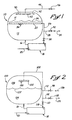
- a prior art propellant tank 10 is partially filled with propellant 12 and has above the propellant an ullage 14.
- the tank 10 is filled with the propellant 12 through a transfer line 16 that directs the propellant from a heat exchanger/liquid filling system 18 to the bottom of the tank.
- the filling system 18 initially receives a propellant stream 20 to fill the tank 10.
- the tank 10 has a manifold 22 for venting ullage gas from the tank 10 during the initial propellant charging process and drawing off warmer propellant 12 from the tank during the propellant densification process.
- the manifold 22 is shown in the upper half of the tank 10 and below the surface 24 of the propellant for densification.
- the manifold 22 is connected to a manifold line 26 that is also connected to the filling system 18.
- the manifold line 26 has a vent line 28 coming off of it.
- the manifold line 26 and the vent line 28 have valves 30 and 32, respectively, to control the flow of material through the lines.
- the valve 30 is located downstream of the tee for the vent line 28.
- the tank 10 is vented through the manifold 22.
- the ullage 14 decreases and needs to be vented.
- the ullage 14 is vented through the manifold 22 and out of the vent line 28.
- the manifold line valve 30 is closed and the vent line valve 32 is open to direct venting gas 34 out through the vent line 28.
- the venting through the manifold 22 continues until orifices 36 in the manifold are submerged, at which time the vent line valve 32 is closed.
- the initial propellant charging process continues until a predetermined full charge of propellant 12 is delivered to the tank 10.
- the propellant 12 is densified.
- the densification process involves removing propellant 12 from the tank 10, cooling the propellant, and directing it back into the tank.
- the manifold 22 is used to draw off propellant 12 and the propellant is directed through the manifold line 26 and the now open manifold line valve 30 and into the heat exchanger/filling system 18.
- the propellant 12 is cooled in the filling system 18 and directed back to the tanks 10 through the transfer line 16.
- the positioning of the manifold 22 in the upper portion of the tank 10 draws off propellant 12 that is warmer than propellant nearer the bottom of the tank.
- the propellant tank 10 is pressurized.
- the tank 10 is isolated from the filling system 18 and the vent line 28.
- the propellant tank 10 is pressurized through pressurization gas 40 being introduced into the ullage 14 through a diffuser 42.
- the diffuser 42 is mounted in the tank 10 such that it is in the ullage.
- the diffuser 42 is designed to direct the incoming pressurization gas 40 away from the propellant surface 24 and reduce heat transfer between the warmer gas and the cooler propellant 12. There are certain advantages to inhibiting heat transfer between the gas 40 and the propellant 12.
- the warmer pressurization gas 40 heats up the propellant 12, thereby detrimentally decreasing the propellant's density.
- the gas 40 cooled by the propellant 12 is denser, thereby requiring a detrimental increase in amount and weight of the pressurization gas tank to achieve the target tank pressure.
- the pressurization gas 40 is directed to the diffuser 42 through a gas line 44.
- the gas line 44 has a gas line valve 46 that is closed during the initial propellant charging process.
- the prior art design for a propellant tank requires two sets of piping, the manifold line 26 and the pressurization gas line 44.
- the prior art design also requires a manifold 22 for venting and recirculating and a separate diffuser for introducing pressurized gas 40 into the tank 10.
- a propellant tank system comprises a combined manifold, a combined manifold line, a pressurizing gas line, and a vent line.
- the combined manifold is located in the propellant tank.
- the combined manifold line functionally connects the combined manifold to a propellant chilling system.
- the pressurizing gas line and the vent line are also functionally connected to the combined manifold line.
- a pressurizing gas line valve is functionally disposed in the pressurizing gas line and a vent line valve is functionally disposed in the vent.
- a combined manifold line valve is functionally disposed in the combined manifold line downstream of where the pressurizing gas line and the vent line functionally connects to the combined manifold line.
- the propellant tank is disposed in a vehicle
- the manifold is disposed proximate a top of the propellant tank
- the propellant chilling system is a heat exchanger/filling system.
- a process for charging a propellant tank comprises the steps of charging the propellant tank, venting gases in the propellant tank, densifying liquid propellant, and pressurizing the propellant tank.
- the propellant tank is charged with liquid propellant.
- the gases in the propellant tank are vented through orifices in the combined manifold, into the combined manifold, and out of the propellant tank.
- the venting step is arrested prior to the liquid propellant submerging the combined manifold orifices.
- the charging step continues such that the the orifices are submerged.
- the liquid propellant in the propellant tank is densified by directing a recirculation stream of the liquid propellant from the propellant tank through the submerged combined manifold orifices, into the combined manifold, out of the propellant tank, cooling and directing the recirculation stream into the propellant tank.
- the propellant tank is pressurized by directing a pressurizing gas stream into the combined manifold, through the combined manifold orifices, and into the propellant tank after the densifying step.
- the venting step further comprises the step of directing the venting gases from the combined manifold, through a combined manifold line, and exiting the combined manifold line through a venting line.
- the densifying step further comprises the step of directing the liquid propellant from the combined manifold, through a combined manifold line, and into a propellant chilling system.
- the pressurizing step further comprises the step of directing the pressurizing gas stream through the combined manifold line and into the combined manifold.
- a further aspect of the invention comprises the step of draining a portion of the liquid propellant from the propellant tank to expose combined manifold orifices to an ullage in the propellant tank.
- the combined manifold is disposed proximate the top of the propellant tank.
- liquid oxidizer is used in place of liquid propellant, with the tank system being for liquid oxidizer.
- a propellant tank 100 has a combined manifold 102 that is used in the processes of venting, recirculating, and pressurizing the tank.
- the tank 100 is shown partially filled with propellant 104 and has above the propellant an ullage 106.
- the tank 100 is filled with the propellant 104 through the transfer line 16 that directs the propellant from the heat exchanger/liquid filling system 18 to the bottom of the tank.
- the filling system 18 initially receives the propellant stream 20 to fill the tank 100.
- the combined manifold 102 is located in the top portion of tank 100.
- a combined manifold line 108 functionally connects the combined manifold 102 to the filling system 18 and has a valve 110 to control flow.
- a pressurizing gas line 112 and a vent line 114 enter the manifold line 108.
- the pressurizing gas line 112 and the vent line 114 have respective valves 116 and 118 to control flow through the lines.
- the process of charging the tank 100 comprises a charging, chilling, and venting gases step; an arresting the venting gases step; a densifying step; and a pressurization step.
- the propellant tank 100 is filled with propellant 104 through the line 16.
- the venting step continues until the orifices 120 of the combined manifold 102 are submerged in the propellant 104.
- Figure 2 shows the surface 122 of the propellant 104 below the combined manifold 102.
- the ullage 106 is vented through the combined manifold 102.
- the tank 100 is vented as propellant fills the tank.
- the vented gases 124 exit through the vent line 114.
- the manifold line valve 110 and the pressurization gas line valve 116 are closed and the vent line valve 118 is open.
- the vented gases 124 may be vented to an environmentally suitable capture device (not shown) for disposal, recovery, or recirculation.
- the vent line valve 118 is closed prior to the combined manifold orifices 120 becoming submerged in the propellant 104.
- Embodiments of the invention may use any suitable system to determine when to initiate the arresting the venting gases step, including level indicators, volume determination systems, and the like.
- the propellant 104 flows through the combined manifold 102 and the combined manifold line 108.
- the flowing propellant 104 is then chilled in the heat exchanger/filling system 18 and recirculated back into the tank 100 through transfer line 16.
- the propellant is chilled and densified in the system 18.
- the tank 100 may have to be pressurized prior to the densifying step, which may be the case when liquid hydrogen is the propellant 104.
- additional liquid propellant 104 may need to be added to the tank 100.
- the volume in the tank 100 is maintained with additional liquid propellant 104 added through line 20 to the heat exchanger/liquid filling system 18 and fed back into the tank 100 through line 16.
- Embodiments of the invention may use any suitable propellant chilling system to cool and densify the propellant 104.
- the combined manifold line valve 110 is open and the pressurizing gas valve 116 and the vent line valve 118 are closed. Additionally, the propellant surface 122 is above the combined manifold orifices 120 during the densifying step, such that the orifices are submerged.
- the pressure in the propellant tank 100 is increased by a pressurization gas stream 126 being directed through the combined manifold 102.
- the manifold orifices 120 may be below the surface 122 during the pressurizing step, such as when pressurizing the tank 100 with helium prior to flight.
- the combined manifold orifices 122 are exposed to the ullage 106 prior to initiating the pressurizing step.
- the liquid propellant 104 is drained from the tank 100 to lower the top surface 120 and expose the orifices 122 to the ullage 106. The draining of the tank 100 may occur through the line 16 or through another line not shown.
- the combined manifold line valve 110 and the vent line valve 118 are closed and the pressurizing gas line valve 116 is opened.
- a pressurization gas stream 126 is directed through the pressurizing gas line 112, through the combined manifold line 108, and into the manifold 102.
- the pressurization gas stream 126 enters the tank ullage 106 and pressurizes the tank.
- the orifices 120 direct the incoming pressurization gas 126 away from the propellant surface 122 to reduce heat transfer between the gas 126 and the propellant 104.
- the shown, and a preferred, embodiment of the invention reduces the weight of the pressurization tank system.
- the embodiment of the invention eliminates one of the fluid distribution devices by having a combined manifold instead of a manifold and a diffuser. Additionally, by having only the combined manifold, one less line going directly to the tank 100 is needed than what is disclosed in the prior art. This reduction in components of the system may result in a beneficial reduction of weight in a preferred embodiment of the invention.
Landscapes
- Engineering & Computer Science (AREA)
- Mechanical Engineering (AREA)
- General Engineering & Computer Science (AREA)
- Chemical & Material Sciences (AREA)
- Combustion & Propulsion (AREA)
- Remote Sensing (AREA)
- Aviation & Aerospace Engineering (AREA)
- Filling Or Discharging Of Gas Storage Vessels (AREA)
Abstract
Description
- This invention relates to propellant storage and, more specifically, relates to densifying the stored propellant.
- Propulsion systems utilizing cryogenic liquid oxygen and/or hydrogen, such as the Space Shuttle, Atlas/Centaur, Delta, etc., are currently filled from the facility storage tanks and subsequently allowed to cool in the flight tanks in order to reject the heat absorbed by the liquid as a result of environmental heat leak, transfer line, and tank wall chill-down. The cooling of the liquid bulk is desirable in order to increase the liquid density so that more impulse mass can be stored in the tank, and also to reduce the liquid vapor pressure so that the tank operating pressure and tank weight is minimized.
- Heat rejection from the liquid bulk is a relatively slow process since it depends on natural convection mechanism and liquid surface evaporation. The degree of liquid cooling through surface evaporation is also limited by the vent system flow resistance (vent valve and line) and the ambient pressure (14.7 psia). Reducing the vent system flow resistance to improve the cool down time and minimize the final bulk temperature results in a relatively large vent valve and line design which represents a vehicle payload weight penalty. Although the current means of densifying the cryogenic liquids through evaporation are simple the process is limited to the saturation density and liquid vapor pressure at one atmosphere.
- The prior art discloses systems that result in reduced weight of a vehicle with a propellant tank and reduced energy required to transport the vehicle. One such system is disclosed in U.S. Patent No. 5,644,920 to Lak et al. entitled "Liquid Propellant Densification," which is incorporated by reference herein in its entirety.
- The prior art also discloses the importance of maintaining propellant tank pressure before and during engine operation. Referring now to Prior Art Figure 1, a prior
art propellant tank 10 is partially filled withpropellant 12 and has above the propellant anullage 14. Thetank 10 is filled with thepropellant 12 through atransfer line 16 that directs the propellant from a heat exchanger/liquid filling system 18 to the bottom of the tank. Thefilling system 18 initially receives apropellant stream 20 to fill thetank 10. - The
tank 10 has amanifold 22 for venting ullage gas from thetank 10 during the initial propellant charging process and drawing offwarmer propellant 12 from the tank during the propellant densification process. Themanifold 22 is shown in the upper half of thetank 10 and below thesurface 24 of the propellant for densification. Themanifold 22 is connected to amanifold line 26 that is also connected to thefilling system 18. Themanifold line 26 has avent line 28 coming off of it. Themanifold line 26 and thevent line 28 havevalves 30 and 32, respectively, to control the flow of material through the lines. The valve 30 is located downstream of the tee for thevent line 28. - During the initial propellant charging process, the
tank 10 is vented through themanifold 22. As the amount of thepropellant 12 in thetank 10 increases, theullage 14 decreases and needs to be vented. Theullage 14 is vented through themanifold 22 and out of thevent line 28. The manifold line valve 30 is closed and thevent line valve 32 is open todirect venting gas 34 out through thevent line 28. The venting through themanifold 22 continues untilorifices 36 in the manifold are submerged, at which time thevent line valve 32 is closed. The initial propellant charging process continues until a predetermined full charge ofpropellant 12 is delivered to thetank 10. - After the initial propellant charging process, the
propellant 12 is densified. The densification process involves removingpropellant 12 from thetank 10, cooling the propellant, and directing it back into the tank. Themanifold 22 is used to draw offpropellant 12 and the propellant is directed through themanifold line 26 and the now open manifold line valve 30 and into the heat exchanger/filling system 18. Thepropellant 12 is cooled in thefilling system 18 and directed back to thetanks 10 through thetransfer line 16. The positioning of themanifold 22 in the upper portion of thetank 10 draws offpropellant 12 that is warmer than propellant nearer the bottom of the tank. - After the densification process, the
propellant tank 10 is pressurized. Thetank 10 is isolated from thefilling system 18 and thevent line 28. Thepropellant tank 10 is pressurized throughpressurization gas 40 being introduced into theullage 14 through adiffuser 42. Thediffuser 42 is mounted in thetank 10 such that it is in the ullage. - The
diffuser 42 is designed to direct theincoming pressurization gas 40 away from thepropellant surface 24 and reduce heat transfer between the warmer gas and thecooler propellant 12. There are certain advantages to inhibiting heat transfer between thegas 40 and thepropellant 12. Thewarmer pressurization gas 40 heats up thepropellant 12, thereby detrimentally decreasing the propellant's density. Thegas 40 cooled by thepropellant 12 is denser, thereby requiring a detrimental increase in amount and weight of the pressurization gas tank to achieve the target tank pressure. - The
pressurization gas 40 is directed to thediffuser 42 through agas line 44. Thegas line 44 has agas line valve 46 that is closed during the initial propellant charging process. - The prior art design for a propellant tank requires two sets of piping, the
manifold line 26 and thepressurization gas line 44. The prior art design also requires amanifold 22 for venting and recirculating and a separate diffuser for introducing pressurizedgas 40 into thetank 10. A need exists for a system that combines the functions of the above items. - In an aspect of the invention, a propellant tank system comprises a combined manifold, a combined manifold line, a pressurizing gas line, and a vent line. The combined manifold is located in the propellant tank. The combined manifold line functionally connects the combined manifold to a propellant chilling system. The pressurizing gas line and the vent line are also functionally connected to the combined manifold line.
- In a further aspect of the invention, a pressurizing gas line valve is functionally disposed in the pressurizing gas line and a vent line valve is functionally disposed in the vent. Further, a combined manifold line valve is functionally disposed in the combined manifold line downstream of where the pressurizing gas line and the vent line functionally connects to the combined manifold line.
- In further aspects of the invention, the propellant tank is disposed in a vehicle, the manifold is disposed proximate a top of the propellant tank, and the propellant chilling system is a heat exchanger/filling system.
- In an aspect of the invention, a process for charging a propellant tank comprises the steps of charging the propellant tank, venting gases in the propellant tank, densifying liquid propellant, and pressurizing the propellant tank. The propellant tank is charged with liquid propellant. The gases in the propellant tank are vented through orifices in the combined manifold, into the combined manifold, and out of the propellant tank. The venting step is arrested prior to the liquid propellant submerging the combined manifold orifices. The charging step continues such that the the orifices are submerged. The liquid propellant in the propellant tank is densified by directing a recirculation stream of the liquid propellant from the propellant tank through the submerged combined manifold orifices, into the combined manifold, out of the propellant tank, cooling and directing the recirculation stream into the propellant tank. The propellant tank is pressurized by directing a pressurizing gas stream into the combined manifold, through the combined manifold orifices, and into the propellant tank after the densifying step.
- In a further aspect of the invention, the venting step further comprises the step of directing the venting gases from the combined manifold, through a combined manifold line, and exiting the combined manifold line through a venting line.
- In a further aspect of the invention, the densifying step further comprises the step of directing the liquid propellant from the combined manifold, through a combined manifold line, and into a propellant chilling system.
- In a further aspect of the invention, the pressurizing step further comprises the step of directing the pressurizing gas stream through the combined manifold line and into the combined manifold.
- A further aspect of the invention comprises the step of draining a portion of the liquid propellant from the propellant tank to expose combined manifold orifices to an ullage in the propellant tank.
- In a further aspect of the invention, the combined manifold is disposed proximate the top of the propellant tank.
- In a further aspect of the invention, liquid oxidizer is used in place of liquid propellant, with the tank system being for liquid oxidizer.
-
- Prior Art Figure 1 shows a propellant tank according to the prior art; and
- Figure 2 shows a propellant tank with a combined manifold according to an embodiment of the invention.
-
- Referring now to Figure 2, a
propellant tank 100 according to an embodiment of the invention has a combinedmanifold 102 that is used in the processes of venting, recirculating, and pressurizing the tank. Thetank 100 is shown partially filled withpropellant 104 and has above the propellant anullage 106. Thetank 100 is filled with thepropellant 104 through thetransfer line 16 that directs the propellant from the heat exchanger/liquid filling system 18 to the bottom of the tank. The fillingsystem 18 initially receives thepropellant stream 20 to fill thetank 100. - The combined
manifold 102 is located in the top portion oftank 100. A combinedmanifold line 108 functionally connects the combinedmanifold 102 to the fillingsystem 18 and has a valve 110 to control flow. Upstream of the manifold line valve 110 a pressurizinggas line 112 and avent line 114 enter themanifold line 108. The pressurizinggas line 112 and thevent line 114 haverespective valves - The process of charging the
tank 100 comprises a charging, chilling, and venting gases step; an arresting the venting gases step; a densifying step; and a pressurization step. - In the charging, chilling, and venting step, the
propellant tank 100 is filled withpropellant 104 through theline 16. The venting step continues until theorifices 120 of the combinedmanifold 102 are submerged in thepropellant 104. Figure 2 shows thesurface 122 of thepropellant 104 below the combinedmanifold 102. As thetank 100 is being filled, the tank is chilled using systems and techniques known to those skilled in the art. Theullage 106 is vented through the combinedmanifold 102. Thetank 100 is vented as propellant fills the tank. The vented gases 124 exit through thevent line 114. During the venting process, the manifold line valve 110 and the pressurizationgas line valve 116 are closed and thevent line valve 118 is open. The vented gases 124 may be vented to an environmentally suitable capture device (not shown) for disposal, recovery, or recirculation. - In the arresting the venting gases step, the
vent line valve 118 is closed prior to the combinedmanifold orifices 120 becoming submerged in thepropellant 104. Embodiments of the invention may use any suitable system to determine when to initiate the arresting the venting gases step, including level indicators, volume determination systems, and the like. - In the densifying step, the
propellant 104 flows through the combinedmanifold 102 and the combinedmanifold line 108. The flowingpropellant 104 is then chilled in the heat exchanger/fillingsystem 18 and recirculated back into thetank 100 throughtransfer line 16. The propellant is chilled and densified in thesystem 18. In some embodiments of the invention, thetank 100 may have to be pressurized prior to the densifying step, which may be the case when liquid hydrogen is thepropellant 104. - During the densifying step, additional
liquid propellant 104 may need to be added to thetank 100. As theliquid propellant 104 is densified, the volume in thetank 100 is maintained with additionalliquid propellant 104 added throughline 20 to the heat exchanger/liquid filling system 18 and fed back into thetank 100 throughline 16. - An example of a chilling process using the heat exchanger/filling
system 18 is disclosed in previously referenced and incorporated U.S. Patent No. 5,6344,920. Embodiments of the invention may use any suitable propellant chilling system to cool and densify thepropellant 104. For the step to occur, the combined manifold line valve 110 is open and the pressurizinggas valve 116 and thevent line valve 118 are closed. Additionally, thepropellant surface 122 is above the combinedmanifold orifices 120 during the densifying step, such that the orifices are submerged. - In the pressurizing step, the pressure in the
propellant tank 100 is increased by apressurization gas stream 126 being directed through the combinedmanifold 102. In an embodiment of the invention, themanifold orifices 120 may be below thesurface 122 during the pressurizing step, such as when pressurizing thetank 100 with helium prior to flight. - In another embodiment of the invention, the combined
manifold orifices 122 are exposed to theullage 106 prior to initiating the pressurizing step. In a preferred embodiment of the invention, theliquid propellant 104 is drained from thetank 100 to lower thetop surface 120 and expose theorifices 122 to theullage 106. The draining of thetank 100 may occur through theline 16 or through another line not shown. - During the pressurizing step, the combined manifold line valve 110 and the
vent line valve 118 are closed and the pressurizinggas line valve 116 is opened. Apressurization gas stream 126 is directed through the pressurizinggas line 112, through the combinedmanifold line 108, and into themanifold 102. Thepressurization gas stream 126 enters thetank ullage 106 and pressurizes the tank. In the preferred embodiment of the invention, theorifices 120 direct theincoming pressurization gas 126 away from thepropellant surface 122 to reduce heat transfer between thegas 126 and thepropellant 104. - The shown, and a preferred, embodiment of the invention reduces the weight of the pressurization tank system. The embodiment of the invention eliminates one of the fluid distribution devices by having a combined manifold instead of a manifold and a diffuser. Additionally, by having only the combined manifold, one less line going directly to the
tank 100 is needed than what is disclosed in the prior art. This reduction in components of the system may result in a beneficial reduction of weight in a preferred embodiment of the invention. - Although presently preferred embodiments of the present invention have been described in detail hereinabove, it should be clearly understood that many variations and/or modifications of the basic inventive concepts herein taught, which may appear to those skilled in the pertinent art, will still fall within the spirit and scope of the present invention, as defined in the appended claims..
Claims (10)
- A tank system for storing a liquid, the liquid being liquid propellant or liquid oxidizer, the system comprising:a. a combined manifold located in a tank;b. a combined manifold line functionally connecting the combined manifold to a liquid chilling system;c. a pressurizing gas line functionally connected to the combined manifold line; andd. a vent line functionally connected to the combined manifold line.
- The tank system of claim 1 further comprising:a. a pressurizing gas line valve being functionally disposed in the pressurizing gas line;b. a vent line valve being functionally disposed in the vent line; andc. a combined manifold line valve being functionally disposed in the combined manifold line downstream of where the pressurizing gas line and the vent line functionally connects to the combined manifold line.
- The tank system of claim 1, wherein the tank is disposed in a vehicle.
- The propellant tank system of claim 1, wherein the manifold is disposed proximate a top of the tank.
- The propellant tank system of claim 1, wherein the liquid chilling system is a heat exchanger/filling system.
- A process for filling a tank with a liquid, the liquid being liquid propellant or liquid oxidizer, the process comprising the steps of:a. charging the tank with the liquid to submerge orifices in a combined manifold that is disposed in the tank;b. venting gases in the propellant tank through the combined manifold orifices, into the combined manifold, and out of the tank;c. arresting the venting step prior to the liquid submerging the combined manifold orifices;d. densifying the liquid in the tank by directing a recirculation stream of the liquid from the tank through the submerged combined manifold orifices, into the combined manifold, out of the tank, cooling the recirculation stream, and directing the recirculation stream back into the tank; ande. pressurizing the tank by directing a pressurizing gas stream into the combined manifold, through the combined manifold orifices, and into the tank.
- The process of claim 6, wherein the venting step further comprises the step of directing the venting gases from the combined manifold, through a combined manifold line, and exiting the combined manifold line through a venting line.
- The process of claim 6, wherein the densifying step further comprises the step of directing the liquid from the combined manifold, through a combined manifold line, and into a chilling system.
- The process of claim 6, wherein the pressurizing step further comprises the step of directing the pressurizing gas stream through the combined manifold line and into the combined manifold.
- The process of claim 6, further comprising the step of draining a portion of the liquid from the tank to expose combined manifold orifices to an ullage in the tank.
Applications Claiming Priority (2)
| Application Number | Priority Date | Filing Date | Title |
|---|---|---|---|
| US09/262,755 US6073450A (en) | 1999-03-04 | 1999-03-04 | Combined diffuser and recirculation manifold in a propellant tank |
| US262755 | 1999-03-04 |
Publications (3)
| Publication Number | Publication Date |
|---|---|
| EP1033301A2 true EP1033301A2 (en) | 2000-09-06 |
| EP1033301A3 EP1033301A3 (en) | 2001-07-18 |
| EP1033301B1 EP1033301B1 (en) | 2005-05-25 |
Family
ID=22998891
Family Applications (1)
| Application Number | Title | Priority Date | Filing Date |
|---|---|---|---|
| EP00200755A Expired - Lifetime EP1033301B1 (en) | 1999-03-04 | 2000-03-03 | Combined diffuser and recirculation manifold in a propellant or oxidizer tank |
Country Status (5)
| Country | Link |
|---|---|
| US (1) | US6073450A (en) |
| EP (1) | EP1033301B1 (en) |
| JP (1) | JP4536196B2 (en) |
| AU (1) | AU774489B2 (en) |
| DE (1) | DE60020279T2 (en) |
Cited By (3)
| Publication number | Priority date | Publication date | Assignee | Title |
|---|---|---|---|---|
| RU2456216C1 (en) * | 2010-12-27 | 2012-07-20 | Открытое акционерное общество "Ракетно-космическая корпорация "Энергия" имени С.П. Королева" | Rocket accelerating engine cryogenic component drain device |
| RU2457160C1 (en) * | 2011-03-03 | 2012-07-27 | Федеральное государственное унитарное предприятие "Научно-производственное объединение им. С.А. Лавочкина" | Shield for space vehicle protection against high-speed meteoroid impact action |
| CN104863752A (en) * | 2015-04-20 | 2015-08-26 | 西安交通大学 | Low-temperature liquid storage box capable of improving gas pressurization effect |
Families Citing this family (13)
| Publication number | Priority date | Publication date | Assignee | Title |
|---|---|---|---|---|
| US7347053B1 (en) | 2001-01-17 | 2008-03-25 | Sierra Lobo, Inc. | Densifier for simultaneous conditioning of two cryogenic liquids |
| US7043925B2 (en) * | 2001-01-17 | 2006-05-16 | Sierra Lobo, Inc. | Densifier for simultaneous conditioning of two cryogenic liquids |
| US6823679B2 (en) | 2003-01-27 | 2004-11-30 | The Boeing Company | Anti-icing fluid injection nozzle |
| CA2506606C (en) * | 2005-06-03 | 2006-09-12 | Westport Research Inc. | Storage tank for a cryogenic liquid and method of re-filling same |
| CN102954345B (en) * | 2011-08-17 | 2015-09-02 | 总装备部工程设计研究总院 | A kind of pressurization system of low-temperature heat-insulation storage tank |
| CN102954820B (en) * | 2011-08-17 | 2015-10-28 | 总装备部工程设计研究总院 | A kind of liquid level measurement system for low-temperature heat-insulation storage tank |
| EP2932147B1 (en) * | 2012-12-14 | 2017-10-18 | Wärtsilä Finland Oy | Method of filling a fuel tank with liquefied gas and liquefied gas fuel system |
| US10808967B2 (en) | 2017-01-16 | 2020-10-20 | Praxair Technology, Inc. | Refrigeration cycle for liquid oxygen densification |
| CN111852690B (en) * | 2020-07-07 | 2021-08-17 | 西安航天动力试验技术研究所 | A Low-Frequency Pulsation Suppression Device for High-Thrust Rocket Engine Ground Test |
| CN112555687B (en) * | 2020-12-28 | 2024-09-24 | 广东华南特种气体研究所有限公司 | Cryogenic liquid output pressurizing system with safety and low energy consumption |
| CN114275194B (en) * | 2021-12-14 | 2024-05-31 | 中国运载火箭技术研究院 | A self-generated pressurization system suitable for multi-operating tank pressurization of nuclear carriers |
| US11939938B2 (en) * | 2022-06-06 | 2024-03-26 | Blue Origin, Llc | Liquid level equalization for propellant tanks |
| CN116696606B (en) * | 2023-08-07 | 2023-10-27 | 东方空间技术(山东)有限公司 | Exhaust device of propellant storage tank of carrier rocket |
Citations (1)
| Publication number | Priority date | Publication date | Assignee | Title |
|---|---|---|---|---|
| US5644920A (en) | 1995-09-25 | 1997-07-08 | Rockwell International Corporation | Liquid propellant densification |
Family Cites Families (6)
| Publication number | Priority date | Publication date | Assignee | Title |
|---|---|---|---|---|
| US2640627A (en) * | 1949-01-15 | 1953-06-02 | Vadolt Trust | Vapor recovery system for fuel tanks |
| US3389555A (en) * | 1962-01-22 | 1968-06-25 | Marquardt Corp | Hydrogen conversion and restorage work cycle |
| US3191395A (en) * | 1963-07-31 | 1965-06-29 | Chicago Bridge & Iron Co | Apparatus for storing liquefied gas near atmospheric pressure |
| US5315530A (en) * | 1990-09-10 | 1994-05-24 | Rockwell International Corporation | Real-time control of complex fluid systems using generic fluid transfer model |
| US5398515A (en) * | 1993-05-19 | 1995-03-21 | Rockwell International Corporation | Fluid management system for a zero gravity cryogenic storage system |
| US6453681B1 (en) * | 2000-01-10 | 2002-09-24 | Boeing North American, Inc. | Methods and apparatus for liquid densification |
-
1999
- 1999-03-04 US US09/262,755 patent/US6073450A/en not_active Expired - Lifetime
-
2000
- 2000-03-01 AU AU19565/00A patent/AU774489B2/en not_active Expired
- 2000-03-03 DE DE60020279T patent/DE60020279T2/en not_active Expired - Lifetime
- 2000-03-03 EP EP00200755A patent/EP1033301B1/en not_active Expired - Lifetime
- 2000-03-03 JP JP2000058910A patent/JP4536196B2/en not_active Expired - Lifetime
Patent Citations (1)
| Publication number | Priority date | Publication date | Assignee | Title |
|---|---|---|---|---|
| US5644920A (en) | 1995-09-25 | 1997-07-08 | Rockwell International Corporation | Liquid propellant densification |
Cited By (3)
| Publication number | Priority date | Publication date | Assignee | Title |
|---|---|---|---|---|
| RU2456216C1 (en) * | 2010-12-27 | 2012-07-20 | Открытое акционерное общество "Ракетно-космическая корпорация "Энергия" имени С.П. Королева" | Rocket accelerating engine cryogenic component drain device |
| RU2457160C1 (en) * | 2011-03-03 | 2012-07-27 | Федеральное государственное унитарное предприятие "Научно-производственное объединение им. С.А. Лавочкина" | Shield for space vehicle protection against high-speed meteoroid impact action |
| CN104863752A (en) * | 2015-04-20 | 2015-08-26 | 西安交通大学 | Low-temperature liquid storage box capable of improving gas pressurization effect |
Also Published As
| Publication number | Publication date |
|---|---|
| EP1033301A3 (en) | 2001-07-18 |
| AU774489B2 (en) | 2004-07-01 |
| DE60020279T2 (en) | 2006-01-26 |
| JP2000283393A (en) | 2000-10-13 |
| AU1956500A (en) | 2000-09-07 |
| DE60020279D1 (en) | 2005-06-30 |
| JP4536196B2 (en) | 2010-09-01 |
| US6073450A (en) | 2000-06-13 |
| EP1033301B1 (en) | 2005-05-25 |
Similar Documents
| Publication | Publication Date | Title |
|---|---|---|
| EP1033301B1 (en) | Combined diffuser and recirculation manifold in a propellant or oxidizer tank | |
| US5644920A (en) | Liquid propellant densification | |
| JP7387394B2 (en) | Methods and equipment for storing and distributing liquefied hydrogen | |
| US6131395A (en) | Propellant densification apparatus and method | |
| JP2022528617A (en) | Equipment and methods for storing and supplying fluid fuel | |
| JP4726305B2 (en) | System and method for densifying liquids | |
| JPH0710099A (en) | Fluid Management Systems and Zero Gravity Cryogenic Storage / Transmission Systems | |
| JPH07217799A (en) | Storage device for cryogenic liquids | |
| US20080016884A1 (en) | Method and Device for Filling Pressure Containers with Low-Boiling Permanent Gases or Gas Mixtures | |
| US20100326097A1 (en) | Methods and systems for densifying a liquid fuel using a liquid nitrogen bath | |
| EP1033303B1 (en) | Cryogenic densification through introduction of a second cryogenic fluid | |
| US20070199941A1 (en) | Method and appartus for storing cryogenic media | |
| US6164078A (en) | Cryogenic liquid heat exchanger system with fluid ejector | |
| CN117307976A (en) | A liquid propellant filling scheme for offshore cryogenic rockets | |
| JP2020527215A (en) | Methods of transferring cryogenic fluids and transfer systems for implementing such methods | |
| US20070186991A1 (en) | Process and arrangement for filling high pressure gas containers using a filling tube | |
| US20080202629A1 (en) | Two-Step-Process for Filling Gas Containers for Airbag Systems and Gas Filling Device for a Two-Step-Filling Process | |
| US2877966A (en) | Common oxygen supply for engine and cabin of high altitude aircraft | |
| US11993403B2 (en) | Advanced cooling for cryogenic powered vehicles | |
| RU2297373C2 (en) | System for filling the upper stage oxidizer tank with supercooled oxygen | |
| Lv et al. | The design and development of the cryogenic compressed gas refueling system | |
| Lak et al. | Liquid propellant densification | |
| RU2252180C2 (en) | Mode of filling a rocket-cosmic system with liquid cryogenic component | |
| US20250129889A1 (en) | Method and device for transferring cryogenic fluid | |
| KR20250170537A (en) | Return system for returning recirculated propulsion liquefied gas, method therefor, and use thereof |
Legal Events
| Date | Code | Title | Description |
|---|---|---|---|
| PUAI | Public reference made under article 153(3) epc to a published international application that has entered the european phase |
Free format text: ORIGINAL CODE: 0009012 |
|
| AK | Designated contracting states |
Kind code of ref document: A2 Designated state(s): DE FR GB IT |
|
| AX | Request for extension of the european patent |
Free format text: AL;LT;LV;MK;RO;SI |
|
| PUAL | Search report despatched |
Free format text: ORIGINAL CODE: 0009013 |
|
| AK | Designated contracting states |
Kind code of ref document: A3 Designated state(s): AT BE CH CY DE DK ES FI FR GB GR IE IT LI LU MC NL PT SE |
|
| AX | Request for extension of the european patent |
Free format text: AL;LT;LV;MK;RO;SI |
|
| RIC1 | Information provided on ipc code assigned before grant |
Free format text: 7B 64G 1/40 A, 7B 64G 5/00 B, 7F 17C 13/00 B, 7F 25J 1/02 B |
|
| 17P | Request for examination filed |
Effective date: 20020107 |
|
| AKX | Designation fees paid |
Free format text: DE FR GB IT |
|
| GRAP | Despatch of communication of intention to grant a patent |
Free format text: ORIGINAL CODE: EPIDOSNIGR1 |
|
| GRAS | Grant fee paid |
Free format text: ORIGINAL CODE: EPIDOSNIGR3 |
|
| GRAA | (expected) grant |
Free format text: ORIGINAL CODE: 0009210 |
|
| RAP1 | Party data changed (applicant data changed or rights of an application transferred) |
Owner name: THE BOEING COMPANY |
|
| AK | Designated contracting states |
Kind code of ref document: B1 Designated state(s): DE FR GB IT |
|
| REG | Reference to a national code |
Ref country code: GB Ref legal event code: FG4D |
|
| REF | Corresponds to: |
Ref document number: 60020279 Country of ref document: DE Date of ref document: 20050630 Kind code of ref document: P |
|
| ET | Fr: translation filed | ||
| PLBE | No opposition filed within time limit |
Free format text: ORIGINAL CODE: 0009261 |
|
| STAA | Information on the status of an ep patent application or granted ep patent |
Free format text: STATUS: NO OPPOSITION FILED WITHIN TIME LIMIT |
|
| 26N | No opposition filed |
Effective date: 20060228 |
|
| REG | Reference to a national code |
Ref country code: FR Ref legal event code: PLFP Year of fee payment: 17 |
|
| REG | Reference to a national code |
Ref country code: FR Ref legal event code: PLFP Year of fee payment: 18 |
|
| REG | Reference to a national code |
Ref country code: FR Ref legal event code: PLFP Year of fee payment: 19 |
|
| PGFP | Annual fee paid to national office [announced via postgrant information from national office to epo] |
Ref country code: DE Payment date: 20190327 Year of fee payment: 20 Ref country code: FR Payment date: 20190325 Year of fee payment: 20 Ref country code: IT Payment date: 20190322 Year of fee payment: 20 |
|
| PGFP | Annual fee paid to national office [announced via postgrant information from national office to epo] |
Ref country code: GB Payment date: 20190404 Year of fee payment: 20 |
|
| REG | Reference to a national code |
Ref country code: DE Ref legal event code: R071 Ref document number: 60020279 Country of ref document: DE |
|
| REG | Reference to a national code |
Ref country code: GB Ref legal event code: PE20 Expiry date: 20200302 |
|
| PG25 | Lapsed in a contracting state [announced via postgrant information from national office to epo] |
Ref country code: GB Free format text: LAPSE BECAUSE OF EXPIRATION OF PROTECTION Effective date: 20200302 |