EP1033220B1 - Mold matrix pin with integral spacing means - Google Patents
Mold matrix pin with integral spacing means Download PDFInfo
- Publication number
- EP1033220B1 EP1033220B1 EP00103572A EP00103572A EP1033220B1 EP 1033220 B1 EP1033220 B1 EP 1033220B1 EP 00103572 A EP00103572 A EP 00103572A EP 00103572 A EP00103572 A EP 00103572A EP 1033220 B1 EP1033220 B1 EP 1033220B1
- Authority
- EP
- European Patent Office
- Prior art keywords
- pin
- mold
- longitudinal axis
- pins
- matrix
- Prior art date
- Legal status (The legal status is an assumption and is not a legal conclusion. Google has not performed a legal analysis and makes no representation as to the accuracy of the status listed.)
- Expired - Lifetime
Links
Images


Classifications
-
- B—PERFORMING OPERATIONS; TRANSPORTING
- B29—WORKING OF PLASTICS; WORKING OF SUBSTANCES IN A PLASTIC STATE IN GENERAL
- B29C—SHAPING OR JOINING OF PLASTICS; SHAPING OF MATERIAL IN A PLASTIC STATE, NOT OTHERWISE PROVIDED FOR; AFTER-TREATMENT OF THE SHAPED PRODUCTS, e.g. REPAIRING
- B29C33/00—Moulds or cores; Details thereof or accessories therefor
- B29C33/38—Moulds or cores; Details thereof or accessories therefor characterised by the material or the manufacturing process
- B29C33/3842—Manufacturing moulds, e.g. shaping the mould surface by machining
-
- B—PERFORMING OPERATIONS; TRANSPORTING
- B29—WORKING OF PLASTICS; WORKING OF SUBSTANCES IN A PLASTIC STATE IN GENERAL
- B29L—INDEXING SCHEME ASSOCIATED WITH SUBCLASS B29C, RELATING TO PARTICULAR ARTICLES
- B29L2011/00—Optical elements, e.g. lenses, prisms
- B29L2011/0083—Reflectors
- B29L2011/0091—Reflex reflectors
-
- Y—GENERAL TAGGING OF NEW TECHNOLOGICAL DEVELOPMENTS; GENERAL TAGGING OF CROSS-SECTIONAL TECHNOLOGIES SPANNING OVER SEVERAL SECTIONS OF THE IPC; TECHNICAL SUBJECTS COVERED BY FORMER USPC CROSS-REFERENCE ART COLLECTIONS [XRACs] AND DIGESTS
- Y10—TECHNICAL SUBJECTS COVERED BY FORMER USPC
- Y10S—TECHNICAL SUBJECTS COVERED BY FORMER USPC CROSS-REFERENCE ART COLLECTIONS [XRACs] AND DIGESTS
- Y10S425/00—Plastic article or earthenware shaping or treating: apparatus
- Y10S425/808—Lens mold
Definitions
- This invention relates to mold pins and in particular to optic or reflex pins having means thereon to space them from adjacent pins when a plurality of the pins are grouped in an pin master or mold matrix.
- a reflex pin or pins are used as examples only and the specification is not limited only to that form of pin.
- a pin master or matrix comprises a plurality of mold pins, for example reflex pins or a combination of optic pins and reflex pins, which are assembled into a specific configuration.
- the matrix (as it will be referred to hereinafter) is used to produce an electroform, by electrodeposition, or other suitable means, and the electroform so produced is then used to manufacture a mold which receives suitable mold material, such as thermoplastic, under pressure for making lens and/or reflective devices such as automobile lamp assemblies.
- the outer lens portion of automotive lamp assemblies include sections made up of reflex elements, the purpose of which is to reflect light from an exterior light source directed at the lamp assembly.
- the reflex portion of a lamp assembly provides the reflective brilliance to a light source directed at the assembly i.e. from the headlights of a vehicle which are being directed at a rear lamp assembly incorporating the reflex elements.
- the brilliance of the reflective elements must meet standards set by various countries.
- Lamp assemblies and their lenses for automotive vehicles are relatively simple to manufacture when the areas of the vehicles on which they are mounted are relatively flat.
- bodies of automotive vehicles are now smoothly contoured both on rear surfaces as well as front surfaces thereof in order to reduce the coefficient of drag and it has become more difficult to manufacture suitable lenses that will blend into these contours and which will still provide the required amount of reflectivity and brilliance required by law.
- lamp assemblies must have lenses that extend into portions of the side surfaces of the vehicle as well as surfaces to the front and rear thereof. There are often compound curvatures to the surfaces to which the lenses must match.
- reflex elements sometimes in combination with optical elements, are manufactured by assembling a large plurality of mold pins (reflex and if necessary optical pins) into a matrix and an electroform is then made by electro-depositing metal on the shaped ends of the mold pins in the matrix and then using the resulting electroform in a mold where plastic material is injected to form the reflected surfaces.
- reflex pins in a bundle or matrix so that they provide the reflective brilliance in the resulting lenses, taking into account the above mentioned body contours of vehicles to which the lenses are attached.
- spacers or wedges for use in combination with mold elements such as optic or reflex pins, in the pin master or matrix assembly.
- the spacers or wedges are selectively located between rows or banks of mold elements in the matrix to provide the required orientation to the optic and/or reflex pins.
- the spacer consists of an elongated body having flat parallel side edges and converging faces which taper towards one another from a major edge to a minor edge. One of the faces has a surface profile to fit the profile of juxtaposed elements in the matrix assembly.
- the present invention addresses the problems referred to above by providing spacing means for use in combination with mold elements such as optic or reflex reflector pins, in the pin block or matrix assembly.
- the spacing means can be selectively located in producing a continuously variable pin axis electroform so as to alter the longitudinal axis of the pins relative to that of adjacent pins whereby the longitudinal axis of the pins are tapered with respect to one another towards the reflex ends of the pins.
- the invention relates to a mold pin for use in a mold matrix as disclosed in claim 1.
- the invention relates to a method of providing a mold pin with means for varying the longitudinal axis thereof as disclosed in claim 11.
- the invention relates to a method of altering the angle of the longitudinal axis of a mold pin as disclosed in claim 14.
- a matrix 10 includes a plurality of mold pins such as reflex pins 12 bundled together for the application of electroform material 14 over the heads 16 of the pins as illustrated. Selected ones of the pins 12 have their longitudinal axis varied relative to adjacent pins in the matrix so that those longitudinal axes are tapered with respect to one another towards the operative or reflex end 16 of the pins.
- Figures 2 and 3 show one example of spacing means according to the invention.
- Pin 12 is provided with a dowel 18 in the sidewall thereof.
- a location on the sidewall of the pin is selected and a socket 20 is drilled in the sidewall 22 normal to the longitudinal axis of the pin.
- the dowel is then inserted in the socket 20 so that the dowel 18 extends normal to the longitudinal axis of the pin.
- the length of protrusion of the dowel sets the degree of taper of the pin relative to adjacent pins in the matrix.
- the length of protrusion can be adjusted in various ways such as by grinding or the like.
- Figure 4 illustrates an example of a plurality of pins 12, 13 and 15 having dowels 18 projecting therefrom and serving to space the upper ends of the pins from one another to the extent of a desired angle.
- a reflex pin has a portion of its upper end formed, for example by machining, to provide a reduced portion 26 leaving a head 28 .
- Pin 24 is then placed in a mold 30 having a sidewall 32 tapered to a degree which, if extended, as illustrated by the dashed line 34 , would meet the side of the pin adjacent the junction 36 with the head 38 of the pin.
- a collar 40 is then molded on to the upper end of the pin around the reduced portion as shown in Figure 6 and, when cooled and removed from the mold, provides the collar 40 which constitutes the means for spacing that pin from adjacent ones in a matrix.
- the central longitudinal axis of the collar 40 is offset from and is tapered with respect to the central longitudinal axis of the pin 24 . It will be noted that the configuration of the offset collar 40 corresponds to that of the pin 24 from which it is offset.
- the length of the collar and the width thereof can be selected to meet the requirements of the spacing between the adjacent pins in the matrix.
- Figures 8 and 9 show a pin bundle 42 in a matrix consisting of a combination of a first group of pins 44 having their longitudinal axis parallel to one another and a second group of pins 46 having spacing means in the form of a collar 40 on each of the pins so that the longitudinal axis of the pins in group 46 have been altered with respect to adjacent pins in that group. As shown in Figure 8, this has the result of orienting the longitudinal axis of the pins in group 46 so that the operative or reflex ends 38 of the pins are directed as desired.
- the material for the spacing collar 40 should be a suitable high impact material such as polycarbonate, one that is resistant to acids and solvents and that adheres well to the pins.
Landscapes
- Engineering & Computer Science (AREA)
- Manufacturing & Machinery (AREA)
- Mechanical Engineering (AREA)
- Moulds For Moulding Plastics Or The Like (AREA)
- Non-Portable Lighting Devices Or Systems Thereof (AREA)
Description
- This invention relates to mold pins and in particular to optic or reflex pins having means thereon to space them from adjacent pins when a plurality of the pins are grouped in an pin master or mold matrix.
- While the invention is applicable to either optic pins or reflex pins used in a mold matrix, a reflex pin or pins are used as examples only and the specification is not limited only to that form of pin.
- A pin master or matrix comprises a plurality of mold pins, for example reflex pins or a combination of optic pins and reflex pins, which are assembled into a specific configuration. The matrix (as it will be referred to hereinafter) is used to produce an electroform, by electrodeposition, or other suitable means, and the electroform so produced is then used to manufacture a mold which receives suitable mold material, such as thermoplastic, under pressure for making lens and/or reflective devices such as automobile lamp assemblies.
- The outer lens portion of automotive lamp assemblies include sections made up of reflex elements, the purpose of which is to reflect light from an exterior light source directed at the lamp assembly. The reflex portion of a lamp assembly provides the reflective brilliance to a light source directed at the assembly i.e. from the headlights of a vehicle which are being directed at a rear lamp assembly incorporating the reflex elements. The brilliance of the reflective elements must meet standards set by various countries.
- Lamp assemblies and their lenses for automotive vehicles are relatively simple to manufacture when the areas of the vehicles on which they are mounted are relatively flat. However, bodies of automotive vehicles are now smoothly contoured both on rear surfaces as well as front surfaces thereof in order to reduce the coefficient of drag and it has become more difficult to manufacture suitable lenses that will blend into these contours and which will still provide the required amount of reflectivity and brilliance required by law.
- There is also a requirement for single, unitary lenses to meet the above mentioned needs for vehicles having smoother, rounded styling but which can also be tailored to the specific functions of the lamp assembly for a particular vehicle. For example, to meet safety requirements of certain countries, lamp assemblies must have lenses that extend into portions of the side surfaces of the vehicle as well as surfaces to the front and rear thereof. There are often compound curvatures to the surfaces to which the lenses must match.
- One example of an automotive vehicle lens using reflex elements is shown in Canadian Patent 2,060,703 issued 17 October 1995 to DBM Reflex Enterprises Inc. This patent illustrates a lens which has a combination of optical elements and reflex elements.
- Conventionally, reflex elements, sometimes in combination with optical elements, are manufactured by assembling a large plurality of mold pins (reflex and if necessary optical pins) into a matrix and an electroform is then made by electro-depositing metal on the shaped ends of the mold pins in the matrix and then using the resulting electroform in a mold where plastic material is injected to form the reflected surfaces.
- It is important in the preparation of a matrix to have the pins oriented properly to provide the directional brilliance and reflectivity in the finished product and it is therefore necessary, in the manufacturer of a reflective matrix, to ensure that the required reflectivity in the finished product is not lost in the curved portion thereof while matching the contour of a vehicle body.
- There are several examples of arranging reflex pins in a bundle or matrix so that they provide the reflective brilliance in the resulting lenses, taking into account the above mentioned body contours of vehicles to which the lenses are attached.
- One example of an attempt to meeting the requirements is shown in U.S. Patent 4,733,946 of March 29, 1988 to Cossetti. In this publication, reflex pins are machined such that their side surfaces are tapered towards the face of the matrix so that when the elements are grouped in a matrix, the tapered pins will provide the necessary curvature. However, while this may be effective, it is a very time consuming and very expensive manner in dealing with the problem.
- In U.S. Patent 5,565,221 of October 15, 1996 assigned to DBM Reflex Enterprises Inc., the problem referred to above is addressed by providing spacers or wedges for use in combination with mold elements such as optic or reflex pins, in the pin master or matrix assembly. The spacers or wedges are selectively located between rows or banks of mold elements in the matrix to provide the required orientation to the optic and/or reflex pins. Thus the necessary reflective surfaces from the prisms will return the requirement amount of reflected light toward a source even when the surface of the product is on a contoured portion of a lamp assembly on a vehicle. The spacer consists of an elongated body having flat parallel side edges and converging faces which taper towards one another from a major edge to a minor edge. One of the faces has a surface profile to fit the profile of juxtaposed elements in the matrix assembly. These spacers or wedges do function well' but problems have been encountered in bundling them in the matrix and maintaining the bundles with the elements in proper orientation.
- Another example of the prior art is shown in the patent to Hedgewick U.S. 3,258,840 of 5 July 1966.
- The present invention addresses the problems referred to above by providing spacing means for use in combination with mold elements such as optic or reflex reflector pins, in the pin block or matrix assembly. The spacing means can be selectively located in producing a continuously variable pin axis electroform so as to alter the longitudinal axis of the pins relative to that of adjacent pins whereby the longitudinal axis of the pins are tapered with respect to one another towards the reflex ends of the pins.
- In accordance with a first aspect, the invention relates to a mold pin for use in a mold matrix as disclosed in claim 1.
- According to a still further aspect, the invention relates to a method of providing a mold pin with means for varying the longitudinal axis thereof as disclosed in claim 11.
- According to a further aspect, the invention relates to a method of altering the angle of the longitudinal axis of a mold pin as disclosed in
claim 14. - The invention is illustrated by way of example in the accompanying drawings in which:
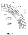
- FIGURE 1 is a schematic plan view of part of an electroform showing mold pins with their longitudinal angles set for a desired curvature in a matrix assembly;
- FIGURE 2 is an elevation view of a reflex pin having tapering means thereon according to one embodiment of the present invention;
- FIGURE 3 is an end view of the mold pin shown in Figure 2;
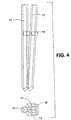
- FIGURE 4 is an elevation view of a plurality of pins having tapering means thereon according to one embodiment of the invention and arranged in a group simulating a portion of a matrix assembly;
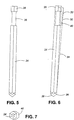
- FIGURE 5 is an elevation view of a mold pin according to a further embodiment of the invention;
- FIGURE 6 is an elevation view similar to Figure 5 showing tapering means applied thereto;
- FIGURE 7 is an end view of the pin shown in Figure 6;
- FIGURE 8 is a plan view of a matrix assembly of a plurality of pins clamped together for making an electroform; and
- FIGURE 9 is a sectional view taken along the line 9-9 of Figure 8.
-
- Referring to Figure 1, a
matrix 10 includes a plurality of mold pins such asreflex pins 12 bundled together for the application ofelectroform material 14 over theheads 16 of the pins as illustrated. Selected ones of thepins 12 have their longitudinal axis varied relative to adjacent pins in the matrix so that those longitudinal axes are tapered with respect to one another towards the operative orreflex end 16 of the pins. - Figures 2 and 3 show one example of spacing means according to the invention.
Pin 12 is provided with adowel 18 in the sidewall thereof. A location on the sidewall of the pin is selected and asocket 20 is drilled in thesidewall 22 normal to the longitudinal axis of the pin. The dowel is then inserted in thesocket 20 so that thedowel 18 extends normal to the longitudinal axis of the pin. The length of protrusion of the dowel sets the degree of taper of the pin relative to adjacent pins in the matrix. The length of protrusion can be adjusted in various ways such as by grinding or the like. - Figure 4 illustrates an example of a plurality of
pins dowels 18 projecting therefrom and serving to space the upper ends of the pins from one another to the extent of a desired angle. - A further embodiment of the invention is illustrated in Figures 5, 6 and 7. A reflex pin has a portion of its upper end formed, for example by machining, to provide a reduced
portion 26 leaving ahead 28.Pin 24 is then placed in amold 30 having asidewall 32 tapered to a degree which, if extended, as illustrated by thedashed line 34, would meet the side of the pin adjacent thejunction 36 with thehead 38 of the pin. Acollar 40 is then molded on to the upper end of the pin around the reduced portion as shown in Figure 6 and, when cooled and removed from the mold, provides thecollar 40 which constitutes the means for spacing that pin from adjacent ones in a matrix. - The central longitudinal axis of the
collar 40 is offset from and is tapered with respect to the central longitudinal axis of thepin 24. It will be noted that the configuration of theoffset collar 40 corresponds to that of thepin 24 from which it is offset. - It will be appreciated that the length of the collar and the width thereof (the amount offset from the pin) can be selected to meet the requirements of the spacing between the adjacent pins in the matrix.
- Figures 8 and 9 show a
pin bundle 42 in a matrix consisting of a combination of a first group ofpins 44 having their longitudinal axis parallel to one another and a second group ofpins 46 having spacing means in the form of acollar 40 on each of the pins so that the longitudinal axis of the pins ingroup 46 have been altered with respect to adjacent pins in that group. As shown in Figure 8, this has the result of orienting the longitudinal axis of the pins ingroup 46 so that the operative or reflex ends 38 of the pins are directed as desired. - The material for the
spacing collar 40 should be a suitable high impact material such as polycarbonate, one that is resistant to acids and solvents and that adheres well to the pins. - While the invention has been described in connection with a specific embodiment thereof and in a specific use, various modifications thereof will occur to those skilled in the art without departing from the scope of the invention as set forth in the appended claims.
- The terms and expressions which have been employed in this specification are used as terms of description and not of limitations, and there is no intention in the use of such terms and expressions to exclude any equivalents of the features shown and described or portions thereof, but it is recognized that various modifications are possible within the scope of the claims.
Claims (14)
- A mold pin (12,24) for use in a mold matrix (10,42), characterized in that said pin (12,24) having means (18,40) thereon to effectively alter the angle of the longitudinal axis of said pin (12,24) relative to that of adjacent pins in said matrix whereby said longitudinal axis of said pins are tapered with respect to one another towards the operative ends (16,38) thereof.
- A mold pin according to claim 1 characterized in that said longitudinal axis altering means comprises a dowel (18) located in a sidewall of said mold pin (12) and extending normal thereto, said dowel location being toward the end of the pin (12) remote from the operative end (16) thereof.
- A mold pin according to claim 1 characterized in that said longitudinal axis altering means comprising a spacing member (40) mounted on, and offset from, said pin (24) at a location remote from the operative end (38) thereof to space said remote location of said pin (24) from adjacent pins in said matrix (10).
- A mold pin according to claim 3 characterized in that said longitudinal axis altering means comprises a collar member (40) molded onto, and offset from, said pin (24) and located remote from the operative end (38) thereof.
- A mold pin according to any one of claims 1-4 wherein said mold pin (12,24) is a reflex pin.
- A mold pin according to claim 3 characterized in that said spacing member comprises a collar (40) molded onto said pin (24) and said collar (40) having its longitudinal axis (34) offset from and tapered with respect to the longitudinal axis of the pin (24).
- A mold pin according to any one of the preceding claims 3-6 characterized in that said axis altering means comprising said collar (40) is positioned on the shank of said pin (24) adjacent the end thereof remote from the operative end (38) and said collar (40) being offset from the central longitudinal axis of said pin.
- A mold pin according to claim 7 characterized in that the shank of said pin (24) has a portion (26) of reduced diameter and said collar (40) is anchored therein.
- A mold pin according to any one of the preceding claims 3-8 wherein said mold pin (12,24) is a reflex pin and said mold matrix (10,46) is for use in the manufacture of a variable pin axis electroform.
- A mold pin according to any one of the preceding claims 4-8 wherein the configuration of said collar (40) corresponds to that of the pin (24) from which it is offset.
- A method of providing a mold pin with means for varying the longitudinal axis of said pin relative to adjacent pins in a mold matrix; said method characterized by the steps of:a) selecting a location on a sidewall of said mold pin (12) ;b) drilling a socket (20) in said sidewall normal to the longitudinal axis of said pin (12); andc) inserting and securing a dowel (18) in said socket (20) whereby said dowel extends normal to the longitudinal axis of said pin (12) whereby the length of protrusion of said dowel sets the degree of taper of said pin relative to an adjacent pin (12) in said matrix (10).
- The method according to claim 11 including the step of machining the outer end of said dowel (18) to provide the desired length of the dowel outwardly of said pins (12).
- The method according to claim 11 or claim 12 wherein the mold pin (12) is a reflex pin.
- A method of altering the angle of the longitudinal axis of a mold pin (24) relative to adjacent pins when used in a mold matrix (10,42), characterized by providing the shank of said pin (24) with a section (26) of reduced diameter, said section (26) being adjacent the pin end remote from its operative end (38); and positioning and anchoring a collar (40) on said pin shank in said reduced diameter section (26), the longitudinal axis of said collar (40) being offset and tapered with respect to the longitudinal axis of the pin (24).
Applications Claiming Priority (2)
| Application Number | Priority Date | Filing Date | Title |
|---|---|---|---|
| CA002262726A CA2262726C (en) | 1999-02-23 | 1999-02-23 | Mold matrix pin with integral spacing means |
| CA2262726 | 1999-02-23 |
Publications (2)
| Publication Number | Publication Date |
|---|---|
| EP1033220A1 EP1033220A1 (en) | 2000-09-06 |
| EP1033220B1 true EP1033220B1 (en) | 2002-12-11 |
Family
ID=4163324
Family Applications (1)
| Application Number | Title | Priority Date | Filing Date |
|---|---|---|---|
| EP00103572A Expired - Lifetime EP1033220B1 (en) | 1999-02-23 | 2000-02-19 | Mold matrix pin with integral spacing means |
Country Status (6)
| Country | Link |
|---|---|
| US (1) | US6540202B1 (en) |
| EP (1) | EP1033220B1 (en) |
| JP (1) | JP3916831B2 (en) |
| CA (1) | CA2262726C (en) |
| DE (2) | DE60000945T4 (en) |
| ES (1) | ES2188438T3 (en) |
Families Citing this family (3)
| Publication number | Priority date | Publication date | Assignee | Title |
|---|---|---|---|---|
| JP4780790B2 (en) * | 2007-03-20 | 2011-09-28 | スタンレー電気株式会社 | Retroreflector |
| DE112010003508B4 (en) | 2009-09-01 | 2022-02-03 | Dbm Reflex Enterprises Inc. | Multicolor vehicle lens with mutually connected TIR reflection prisms and injection molding device |
| DE202016100986U1 (en) | 2016-02-25 | 2017-05-29 | Automotive Lighting Reutlingen Gmbh | Luminaire for motor vehicles |
Family Cites Families (13)
| Publication number | Priority date | Publication date | Assignee | Title |
|---|---|---|---|---|
| US1591572A (en) * | 1925-02-05 | 1926-07-06 | Jonathan C Stimson | Process and apparatus for making central triple reflectors |
| US3069721A (en) * | 1960-03-04 | 1962-12-25 | Ciba Ltd | Tools for making surface patterns |
| US3277535A (en) * | 1963-10-21 | 1966-10-11 | Continental Reflectors Inc | Molding apparatus for reflecting devices |
| US3258840A (en) | 1963-12-05 | 1966-07-05 | Hedgewick Peter | Method of making a core for molding reflectors |
| US3417959A (en) * | 1966-11-14 | 1968-12-24 | Minnesota Mining & Mfg | Die for forming retro-reflective article |
| US3443281A (en) * | 1967-07-24 | 1969-05-13 | Rupert Mfg Co | Molding pin,matrix,and molding assembly for manufacture of reflective devices |
| US4066236A (en) * | 1976-06-25 | 1978-01-03 | Beatrice Foods Co. | Cube corner type retroreflector bodies and molds made therewith |
| IT8383524A0 (en) | 1983-12-27 | 1983-12-27 | Seima Italiana Spa | BARS FOR REFLECTORS. |
| EP0199720A1 (en) * | 1984-11-05 | 1986-11-05 | Olavi MÄKINEN | Adjustable mould |
| CA2060703C (en) * | 1992-02-05 | 1995-10-17 | Italo Caroli | Lens and method of making same |
| CA2099456C (en) | 1993-06-30 | 1997-02-18 | Italo Caroli | Spacing means for reflex pin block |
| CA2120996C (en) | 1994-04-11 | 1998-04-28 | Italo Caroli | Apparatus and method of making reflex molds |
| US6171095B1 (en) * | 1998-06-19 | 2001-01-09 | Hallmark Technologies, Inc. | Multiple axes electroform |
-
1999
- 1999-02-23 CA CA002262726A patent/CA2262726C/en not_active Expired - Lifetime
-
2000
- 2000-02-18 US US09/507,513 patent/US6540202B1/en not_active Expired - Lifetime
- 2000-02-19 EP EP00103572A patent/EP1033220B1/en not_active Expired - Lifetime
- 2000-02-19 DE DE60000945T patent/DE60000945T4/en not_active Expired - Lifetime
- 2000-02-19 ES ES00103572T patent/ES2188438T3/en not_active Expired - Lifetime
- 2000-02-19 DE DE60000945A patent/DE60000945D1/en not_active Expired - Lifetime
- 2000-02-23 JP JP2000046415A patent/JP3916831B2/en not_active Expired - Lifetime
Also Published As
| Publication number | Publication date |
|---|---|
| CA2262726A1 (en) | 2000-08-23 |
| CA2262726C (en) | 2003-11-04 |
| DE60000945T2 (en) | 2003-09-04 |
| JP3916831B2 (en) | 2007-05-23 |
| US6540202B1 (en) | 2003-04-01 |
| JP2000296525A (en) | 2000-10-24 |
| DE60000945T4 (en) | 2010-03-11 |
| ES2188438T3 (en) | 2003-07-01 |
| EP1033220A1 (en) | 2000-09-06 |
| DE60000945D1 (en) | 2003-01-23 |
Similar Documents
| Publication | Publication Date | Title |
|---|---|---|
| DE19812794B4 (en) | Motor vehicle lighting system with an evenly thick optical element designed as a thin plate | |
| US7682533B2 (en) | Injection molding process for forming a retroreflector | |
| US3258840A (en) | Method of making a core for molding reflectors | |
| JP2002507945A (en) | Cube corner sheet mold and method of manufacturing the mold | |
| CA2005302A1 (en) | Collapsible core | |
| EP1033220B1 (en) | Mold matrix pin with integral spacing means | |
| CA2169807C (en) | Reflex pin with adjusted angle | |
| US5657169A (en) | Lens and method of making same | |
| US4747981A (en) | Method of molding a urethane reflector | |
| US7261469B1 (en) | Precision insert for molding ferrules and associated methods of manufacture | |
| US6171095B1 (en) | Multiple axes electroform | |
| EP0658135B1 (en) | Spacing means for reflex pin block | |
| US6439872B1 (en) | Apparatus for manufacturing lenses for vehicle lamps | |
| US5663827A (en) | Polygonal mirror of synthetic resin and producing method thereof | |
| US5610762A (en) | Apparatus and method of making reflex molds | |
| EP1074378B1 (en) | Method for making a retroreflective plate and a pin unit for making said retroreflective plate | |
| DE112010003508B4 (en) | Multicolor vehicle lens with mutually connected TIR reflection prisms and injection molding device | |
| US6471893B1 (en) | Method for making a retroreflective plate and a pin unit for making said retroreflective plate | |
| JP4287241B2 (en) | Reflex reflector molding mold manufacturing method | |
| US5779340A (en) | Vehicle lamp and method of manufacturing the same | |
| JPH0749437A (en) | Optical multicore plastic connector | |
| JP2005125649A (en) | Manufacturing method for die for forming reflex reflector | |
| US20080231954A1 (en) | Reflex reflector |
Legal Events
| Date | Code | Title | Description |
|---|---|---|---|
| PUAI | Public reference made under article 153(3) epc to a published international application that has entered the european phase |
Free format text: ORIGINAL CODE: 0009012 |
|
| AK | Designated contracting states |
Kind code of ref document: A1 Designated state(s): DE ES FR GB IT |
|
| AX | Request for extension of the european patent |
Free format text: AL;LT;LV;MK;RO;SI |
|
| 17P | Request for examination filed |
Effective date: 20010207 |
|
| AKX | Designation fees paid |
Free format text: DE ES FR GB IT |
|
| 17Q | First examination report despatched |
Effective date: 20010830 |
|
| GRAG | Despatch of communication of intention to grant |
Free format text: ORIGINAL CODE: EPIDOS AGRA |
|
| GRAG | Despatch of communication of intention to grant |
Free format text: ORIGINAL CODE: EPIDOS AGRA |
|
| GRAH | Despatch of communication of intention to grant a patent |
Free format text: ORIGINAL CODE: EPIDOS IGRA |
|
| GRAH | Despatch of communication of intention to grant a patent |
Free format text: ORIGINAL CODE: EPIDOS IGRA |
|
| GRAA | (expected) grant |
Free format text: ORIGINAL CODE: 0009210 |
|
| AK | Designated contracting states |
Kind code of ref document: B1 Designated state(s): DE ES FR GB IT |
|
| REG | Reference to a national code |
Ref country code: GB Ref legal event code: FG4D |
|
| REF | Corresponds to: |
Ref document number: 60000945 Country of ref document: DE Date of ref document: 20030123 |
|
| REG | Reference to a national code |
Ref country code: ES Ref legal event code: FG2A Ref document number: 2188438 Country of ref document: ES Kind code of ref document: T3 |
|
| ET | Fr: translation filed | ||
| PLBE | No opposition filed within time limit |
Free format text: ORIGINAL CODE: 0009261 |
|
| STAA | Information on the status of an ep patent application or granted ep patent |
Free format text: STATUS: NO OPPOSITION FILED WITHIN TIME LIMIT |
|
| 26N | No opposition filed |
Effective date: 20030912 |
|
| PGFP | Annual fee paid to national office [announced via postgrant information from national office to epo] |
Ref country code: ES Payment date: 20080229 Year of fee payment: 9 |
|
| PGFP | Annual fee paid to national office [announced via postgrant information from national office to epo] |
Ref country code: GB Payment date: 20080227 Year of fee payment: 9 |
|
| GBPC | Gb: european patent ceased through non-payment of renewal fee |
Effective date: 20090219 |
|
| REG | Reference to a national code |
Ref country code: ES Ref legal event code: FD2A Effective date: 20090220 |
|
| PG25 | Lapsed in a contracting state [announced via postgrant information from national office to epo] |
Ref country code: GB Free format text: LAPSE BECAUSE OF NON-PAYMENT OF DUE FEES Effective date: 20090219 |
|
| PG25 | Lapsed in a contracting state [announced via postgrant information from national office to epo] |
Ref country code: ES Free format text: LAPSE BECAUSE OF NON-PAYMENT OF DUE FEES Effective date: 20090220 |
|
| REG | Reference to a national code |
Ref country code: FR Ref legal event code: PLFP Year of fee payment: 17 |
|
| REG | Reference to a national code |
Ref country code: FR Ref legal event code: PLFP Year of fee payment: 18 |
|
| REG | Reference to a national code |
Ref country code: FR Ref legal event code: PLFP Year of fee payment: 19 |
|
| PGFP | Annual fee paid to national office [announced via postgrant information from national office to epo] |
Ref country code: FR Payment date: 20190123 Year of fee payment: 20 Ref country code: DE Payment date: 20190122 Year of fee payment: 20 Ref country code: IT Payment date: 20190122 Year of fee payment: 20 |
|
| REG | Reference to a national code |
Ref country code: DE Ref legal event code: R071 Ref document number: 60000945 Country of ref document: DE |