EP1033063B1 - Feedback cancellation apparatus and methods - Google Patents
Feedback cancellation apparatus and methods Download PDFInfo
- Publication number
- EP1033063B1 EP1033063B1 EP98956651A EP98956651A EP1033063B1 EP 1033063 B1 EP1033063 B1 EP 1033063B1 EP 98956651 A EP98956651 A EP 98956651A EP 98956651 A EP98956651 A EP 98956651A EP 1033063 B1 EP1033063 B1 EP 1033063B1
- Authority
- EP
- European Patent Office
- Prior art keywords
- filter
- hearing aid
- feedback
- signal
- output
- Prior art date
- Legal status (The legal status is an assumption and is not a legal conclusion. Google has not performed a legal analysis and makes no representation as to the accuracy of the status listed.)
- Expired - Lifetime
Links
- 238000000034 method Methods 0.000 title claims description 13
- 238000012545 processing Methods 0.000 claims abstract description 76
- 230000005236 sound signal Effects 0.000 claims abstract description 51
- 230000003044 adaptive effect Effects 0.000 claims description 35
- 238000013461 design Methods 0.000 claims description 12
- 238000012360 testing method Methods 0.000 claims description 6
- 230000008014 freezing Effects 0.000 claims description 4
- 238000007710 freezing Methods 0.000 claims description 4
- 230000007613 environmental effect Effects 0.000 claims description 2
- 230000006978 adaptation Effects 0.000 description 28
- 239000000523 sample Substances 0.000 description 20
- 238000010586 diagram Methods 0.000 description 14
- 230000006870 function Effects 0.000 description 14
- 238000012546 transfer Methods 0.000 description 14
- 230000004044 response Effects 0.000 description 13
- 238000013459 approach Methods 0.000 description 8
- 230000001629 suppression Effects 0.000 description 6
- 230000009977 dual effect Effects 0.000 description 4
- 230000000694 effects Effects 0.000 description 4
- 230000008859 change Effects 0.000 description 3
- 238000005094 computer simulation Methods 0.000 description 3
- 206010041232 sneezing Diseases 0.000 description 3
- 208000032041 Hearing impaired Diseases 0.000 description 2
- 230000001055 chewing effect Effects 0.000 description 2
- 238000012937 correction Methods 0.000 description 2
- 230000003111 delayed effect Effects 0.000 description 2
- 239000000945 filler Substances 0.000 description 2
- 238000001914 filtration Methods 0.000 description 2
- 238000010438 heat treatment Methods 0.000 description 2
- 230000006872 improvement Effects 0.000 description 2
- 230000010355 oscillation Effects 0.000 description 2
- 230000008569 process Effects 0.000 description 2
- 238000012552 review Methods 0.000 description 2
- 241001135254 Bisgaard taxa Species 0.000 description 1
- 235000008733 Citrus aurantifolia Nutrition 0.000 description 1
- 235000011941 Tilia x europaea Nutrition 0.000 description 1
- 230000003321 amplification Effects 0.000 description 1
- 230000003542 behavioural effect Effects 0.000 description 1
- 230000000903 blocking effect Effects 0.000 description 1
- 238000012512 characterization method Methods 0.000 description 1
- 238000007906 compression Methods 0.000 description 1
- 230000006835 compression Effects 0.000 description 1
- 238000011161 development Methods 0.000 description 1
- 230000018109 developmental process Effects 0.000 description 1
- 229940079593 drug Drugs 0.000 description 1
- 239000003814 drug Substances 0.000 description 1
- 238000005516 engineering process Methods 0.000 description 1
- 238000009472 formulation Methods 0.000 description 1
- 230000001771 impaired effect Effects 0.000 description 1
- 238000009533 lab test Methods 0.000 description 1
- 239000004571 lime Substances 0.000 description 1
- 238000005259 measurement Methods 0.000 description 1
- 239000000203 mixture Substances 0.000 description 1
- 238000003199 nucleic acid amplification method Methods 0.000 description 1
- 238000005070 sampling Methods 0.000 description 1
- 230000035945 sensitivity Effects 0.000 description 1
- 238000001228 spectrum Methods 0.000 description 1
- 238000013022 venting Methods 0.000 description 1
- 239000002023 wood Substances 0.000 description 1
Images


Classifications
-
- H—ELECTRICITY
- H04—ELECTRIC COMMUNICATION TECHNIQUE
- H04R—LOUDSPEAKERS, MICROPHONES, GRAMOPHONE PICK-UPS OR LIKE ACOUSTIC ELECTROMECHANICAL TRANSDUCERS; DEAF-AID SETS; PUBLIC ADDRESS SYSTEMS
- H04R25/00—Deaf-aid sets, i.e. electro-acoustic or electro-mechanical hearing aids; Electric tinnitus maskers providing an auditory perception
- H04R25/45—Prevention of acoustic reaction, i.e. acoustic oscillatory feedback
- H04R25/453—Prevention of acoustic reaction, i.e. acoustic oscillatory feedback electronically
-
- H—ELECTRICITY
- H04—ELECTRIC COMMUNICATION TECHNIQUE
- H04R—LOUDSPEAKERS, MICROPHONES, GRAMOPHONE PICK-UPS OR LIKE ACOUSTIC ELECTROMECHANICAL TRANSDUCERS; DEAF-AID SETS; PUBLIC ADDRESS SYSTEMS
- H04R25/00—Deaf-aid sets, i.e. electro-acoustic or electro-mechanical hearing aids; Electric tinnitus maskers providing an auditory perception
- H04R25/50—Customised settings for obtaining desired overall acoustical characteristics
- H04R25/505—Customised settings for obtaining desired overall acoustical characteristics using digital signal processing
-
- H—ELECTRICITY
- H04—ELECTRIC COMMUNICATION TECHNIQUE
- H04R—LOUDSPEAKERS, MICROPHONES, GRAMOPHONE PICK-UPS OR LIKE ACOUSTIC ELECTROMECHANICAL TRANSDUCERS; DEAF-AID SETS; PUBLIC ADDRESS SYSTEMS
- H04R29/00—Monitoring arrangements; Testing arrangements
- H04R29/004—Monitoring arrangements; Testing arrangements for microphones
- H04R29/005—Microphone arrays
- H04R29/006—Microphone matching
Definitions
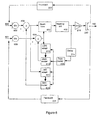
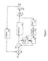
- Figure 6 shows a preferred embodiment of a two input (600, 601) hearing aid according to the present invention. This embodiment is very similar to that shown in Figure 4, and elements having the same reference number are the same.
Landscapes
- General Health & Medical Sciences (AREA)
- Neurosurgery (AREA)
- Otolaryngology (AREA)
- Physics & Mathematics (AREA)
- Engineering & Computer Science (AREA)
- Acoustics & Sound (AREA)
- Signal Processing (AREA)
- Health & Medical Sciences (AREA)
- Circuit For Audible Band Transducer (AREA)
- Soundproofing, Sound Blocking, And Sound Damping (AREA)
- Gas Separation By Absorption (AREA)
- External Artificial Organs (AREA)
- Orthopedics, Nursing, And Contraception (AREA)
- Treating Waste Gases (AREA)
- Filters That Use Time-Delay Elements (AREA)
- Electrostatic, Electromagnetic, Magneto- Strictive, And Variable-Resistance Transducers (AREA)
- General Induction Heating (AREA)
Abstract
Description
Engebretson, A.M., O'Connell, M.P., and Gong, F., "An adaptive feedback equalization algorithm for the CID digital hearing aid", Proc. 12th Annual Int. Conf. of the IEEE Eng. in Medicine and Biology Soc.,
Kates, J.M., "Feedback cancellation in hearing aids: Results from a computer simulation", IEEE Trans. Sig. Proc., Vol.39, pp 553-562, 1991; Dyrlund, O., and Bisgaard, N., "Acoustic feedback margin improvements in hearing instruments using a prototype DFS (digital feedback suppression) system", Scand. Audiol., Vol. 20, pp 49-53, 1991;
Engebretson, A.M., and French-St. George, M., "Properties of an adaptive feedback equalization algorithm", J. Rehab. Res. and Devel., Vol. 30, pp 8-16, 1993; Engebretson, A.M., O'Connell, M.P., and Zheng, B., "Electronic filters, hearing aids, and methods", U.S. Pat. No. 5,016,280;
Williamson, M.J., and Bustamante, D.K., "Feedback suppression in digital signal processing hearing aids," U.S. Pat. No. 5,091,952).
characterised in that said feedback cancellation means includes a first, frozen, pole filter modelling essentially constant parts of a hearing aid feedback path, and
a second, adaptive, filter continuously adapting to changes in the hearing aid feedback path that occur in daily use. The second, adaptive filter may be a FIR filter. The first, frozen filter, may be an IIR filter.


Claims (19)
- A hearing aid comprising:wherein said feedback cancellation means (110, 114, 118, 122) forms a feedback path from the output of the hearing aid processing means (106) to the input of the subtracting means (102), characterised in that, said feedback cancellation means includesa microphone for converting sound into an audio signal;feedback cancellation means (110, 114, 118, 122) including means for estimating a physical feedback signal of the hearing aid, and means for modelling a signal processing feedback signal to compensate for the estimated physical feedback signal;subtracting means (102), connected to the output of the microphone and the output of the feedback cancellation means (110, 114, 118, 122), for subtracting the signal processing feedback signal from the audio signal to form a compensated audio signal;hearing aid processing means (106), connected to the output of the subtracting means (102), for processing the compensated audio signal; andspeaker means, connected to the output of the hearing aid processing means (106), for converting the processed compensated audio signal into a sound signal;a first filter (114) for modelling near constant factors in the physical feedback path, anda second, quickly varying, filter (118) for modelling variable factors in the physical feedback path;wherein the first filter (114) varies substantially slower than the second filter (118).
- The hearing aid of claim 1, characterised by further including:means for designing the first filter (114) when the hearing aid is turned on; and means for freezing the first filter design.
- The hearing aid of claim 1, characterised in that the first filter (114) is the denominator of an IIR filter and the second filter (118) is the numerator of said IIR filter.
- The hearing aid of claim 1, characterised in that the first filter (114) is an IIR filter and the second filter (118) is an FIR filter.
- The hearing aid of claim 1, characterised in that the first and/or second filter (114, 118) is an adaptive filter.
- The hearing aid of claim 1, characterised in that said first filter (114) models a part of the feedback path from the group consisting of microphone, amplifier and receiver resonances, and the resonant behaviour of the basic feedback path.
- A hearing aid comprising:characterised in that, said feedback cancellation means includes a slower varying filter (606), connected to the output of the hearing aid processing means 5 (402), for modelling near constant environmental factors in one of the physical feedback paths (222; 224);a first microphone (602) for converting sound into a first audio signal;a second microphone (603) for converting sound into a second audio signal;feedback cancellation means (214, 606, 610, 611, 612, 613) including means for estimating physical feedback signals to each microphone (602, 603) of the hearing aid, and means for modelling a first signal processing feedback signal to compensate for the estimated physical feedback signal to the first microphone (602) and a second signal processing feedback signal to compensate for the estimated physical feedback signal to the second microphone (603);means for subtracting (608) the first signal processing feedback signal from the first audio signal to form a first compensated audio signal;means for subtracting (609) the second signal processing feedback signal from the second audio signal to form a second compensated audio signal;beamforming means (650), connected to each subtracting means (608, 609), to combine the compensated audio signals into a beamformed signal;hearing aid processing means (402), connected to the beamforming means (650), for processing the beamformed signal; andspeaker means (220), connected to the output of the hearing aid processing means (402), for converting the processed beamformed signal into a sound signal;a first quickly varying filter (613), connected to the output of the slower varying filter (606) and providing an input to the first subtraction means (608), for modelling variable factors in the first feedback path (222); anda second quickly varying filter (612), connected to the output of the slower varying filter (606) and providing an input to the second subtraction means (609), for modelling variable factors in the second feedback path (224);wherein said slower varying filter (606) varies substantially slower than said quickly varying filters (612, 613).
- The hearing aid of claim 7, characterised by further including:means for designing the slower varying filter (606) when the hearing aid is turned on; andmeans for freezing the slower varying filter design.
- The hearing aid of claim 7, characerised in that the first quickly varying filter (613) is the numerator of a first IIR filter, the second quickly varying filter (612) is the numerator of a second IIR filter, and the slower varying filter (606) is based upon the denominator of at least one of said first and second IIR filters.
- The hearing aid of claim 7, characterised in that the slower varying filter (606) is an IIR filter and the rapidly varying filters (612, 613) are FIR filters.
- The hearing aid of claim 7, characterised in that the means for designing the slower varying filter (606) further includes means for detuning the slower varying filter (606), and the means for designing the quickly varying filters (612, 613) further includes means for adapting the quickly varying filters (612, 613) to the detuned slower varying filter (606).
- The hearing aid of claim 7, characterised in that said slower varying filter (606) and/or said quickly varying filters (612, 613) is an adaptive filter.
- The hearing aid of claim 7, characterised in that said slower varying filter (606) models a part of the feedback path from the group consisting of microphone, amplifier and receiver resonances, and the resonant behaviour of the basic feedback path.
- A method for compensating for feedback noise in a hearing aid comprising the steps of:characterised by further including the steps ofturning on the hearing aid;configuring the hearing aid to operate in an open loop manner;inserting a test signal into the hearing aid output;estimating the feedback noise;designing a first, slower varying filter and a second, quickly varying filter to form a feedback path within the hearing aid to compensate for the estimated feedback noise;configuring the hearing aid to operate in a closed loop manner; andadapting at least the second filter to account for changes in the feedback environment.
- The method of claim 14, characterised by further comprising the steps while operating in open loop of:freezing the first filter after the designing step;detuning the first filter; andadapting the second filter to the detuned first filter.
- The method of claim 14, characterised by further comprising the step of:slowly adapting the first filter to account for slowly changing factors in the feedback path.
- A hearing aid comprising:wherein said feedback cancellation means (214, 206, 212, 210) forms a feedback path from the output of the hearing aid processing means (402) to the input of the subtracting means (208), characterised in that said feedback cancellation means includes a first, frozen, pole filter (206) modelling essentially constant parts of a hearing aid feedback path (222), anda microphone (202) for converting sound into an audio signal;feedback cancellation means (214, 206, 212, 210) including means for estimating a physical feedback signal of the hearing aid, and means for modelling a signal processing feedback signal to compensate for the estimated physical feedback signal;subtracting means (208), connected to the output of the microphone (202) and the output of the feedback cancellation means (214, 206, 212, 210), for subtracting the signal processing feedback signal from the audio signal to form a compensated audio signal;hearing aid processing means (402), connected to the output of the subtracting means (208), for processing the compensated audio signal; andspeaker means (220), connected to the output of the hearing aid processing means (402), for converting the processed compensated audio signal into a sound signal;
a second, adaptive, filter (212) continuously adapting to changes in the hearing aid feedback path (222) that occur in daily use. - A hearing aid according to claim 17, characterised in that the second, adaptive filter (212) is a FIR filter.
- A hearing aid according to claim 17 or 18, characterised in that the first, frozen filter (206) is an IIR filter.
Priority Applications (1)
| Application Number | Priority Date | Filing Date | Title |
|---|---|---|---|
| EP03076370A EP1545152A3 (en) | 1997-11-18 | 1998-11-07 | Feedback cancellation apparatus and methods |
Applications Claiming Priority (3)
| Application Number | Priority Date | Filing Date | Title |
|---|---|---|---|
| US08/972,265 US6072884A (en) | 1997-11-18 | 1997-11-18 | Feedback cancellation apparatus and methods |
| US972265 | 1997-11-18 | ||
| PCT/US1998/023666 WO1999026453A1 (en) | 1997-11-18 | 1998-11-07 | Feedback cancellation apparatus and methods |
Related Child Applications (1)
| Application Number | Title | Priority Date | Filing Date |
|---|---|---|---|
| EP03076370A Division EP1545152A3 (en) | 1997-11-18 | 1998-11-07 | Feedback cancellation apparatus and methods |
Publications (2)
| Publication Number | Publication Date |
|---|---|
| EP1033063A1 EP1033063A1 (en) | 2000-09-06 |
| EP1033063B1 true EP1033063B1 (en) | 2003-05-02 |
Family
ID=25519430
Family Applications (2)
| Application Number | Title | Priority Date | Filing Date |
|---|---|---|---|
| EP98956651A Expired - Lifetime EP1033063B1 (en) | 1997-11-18 | 1998-11-07 | Feedback cancellation apparatus and methods |
| EP03076370A Withdrawn EP1545152A3 (en) | 1997-11-18 | 1998-11-07 | Feedback cancellation apparatus and methods |
Family Applications After (1)
| Application Number | Title | Priority Date | Filing Date |
|---|---|---|---|
| EP03076370A Withdrawn EP1545152A3 (en) | 1997-11-18 | 1998-11-07 | Feedback cancellation apparatus and methods |
Country Status (7)
| Country | Link |
|---|---|
| US (1) | US6072884A (en) |
| EP (2) | EP1033063B1 (en) |
| AT (1) | ATE239347T1 (en) |
| AU (1) | AU1312399A (en) |
| DE (1) | DE69814142T2 (en) |
| DK (1) | DK1033063T3 (en) |
| WO (1) | WO1999026453A1 (en) |
Cited By (7)
| Publication number | Priority date | Publication date | Assignee | Title |
|---|---|---|---|---|
| EP2276272A1 (en) | 2009-06-30 | 2011-01-19 | Siemens Medical Instruments Pte. Ltd. | Hearing aid and method for suppressing feedback |
| EP2317779A2 (en) | 2009-10-29 | 2011-05-04 | Siemens Medical Instruments Pte. Ltd. | Hearing aid and method for feedback suppression with directional microphone |
| DE102009060094A1 (en) | 2009-12-22 | 2011-06-30 | Siemens Medical Instruments Pte. Ltd. | Method and hearing aid for feedback detection and suppression with a directional microphone |
| DE102010006154A1 (en) | 2010-01-29 | 2011-08-04 | Siemens Medical Instruments Pte. Ltd. | Hearing aid with frequency shift and associated method |
| WO2012001010A1 (en) | 2010-07-02 | 2012-01-05 | Siemens Medical Instruments Pte. Ltd. | Method for the operation of a hearing device and hearing device with variable frequency shift |
| US12183341B2 (en) | 2008-09-22 | 2024-12-31 | St Casestech, Llc | Personalized sound management and method |
| US12249326B2 (en) | 2007-04-13 | 2025-03-11 | St Case1Tech, Llc | Method and device for voice operated control |
Families Citing this family (122)
| Publication number | Priority date | Publication date | Assignee | Title |
|---|---|---|---|---|
| US6885752B1 (en) | 1994-07-08 | 2005-04-26 | Brigham Young University | Hearing aid device incorporating signal processing techniques |
| US6434246B1 (en) * | 1995-10-10 | 2002-08-13 | Gn Resound As | Apparatus and methods for combining audio compression and feedback cancellation in a hearing aid |
| US6498858B2 (en) * | 1997-11-18 | 2002-12-24 | Gn Resound A/S | Feedback cancellation improvements |
| US6201875B1 (en) | 1998-03-17 | 2001-03-13 | Sonic Innovations, Inc. | Hearing aid fitting system |
| US7254199B1 (en) * | 1998-09-14 | 2007-08-07 | Massachusetts Institute Of Technology | Location-estimating, null steering (LENS) algorithm for adaptive array processing |
| ATE335309T1 (en) | 1998-11-13 | 2006-08-15 | Bitwave Private Ltd | SIGNAL PROCESSING APPARATUS AND METHOD |
| US6380892B1 (en) * | 1999-04-02 | 2002-04-30 | Lg Information & Communications, Ltd. | Adaptive beamforming method in an IMT-2000 system |
| US6408318B1 (en) | 1999-04-05 | 2002-06-18 | Xiaoling Fang | Multiple stage decimation filter |
| US6434247B1 (en) * | 1999-07-30 | 2002-08-13 | Gn Resound A/S | Feedback cancellation apparatus and methods utilizing adaptive reference filter mechanisms |
| ATE289152T1 (en) | 1999-09-10 | 2005-02-15 | Starkey Lab Inc | AUDIO SIGNAL PROCESSING |
| US6480610B1 (en) * | 1999-09-21 | 2002-11-12 | Sonic Innovations, Inc. | Subband acoustic feedback cancellation in hearing aids |
| AU2005203487B2 (en) * | 1999-11-22 | 2007-08-30 | Brigham Young University | Hearing aid device incorporating signal processing techniques |
| US8085943B2 (en) * | 1999-11-29 | 2011-12-27 | Bizjak Karl M | Noise extractor system and method |
| US6757395B1 (en) | 2000-01-12 | 2004-06-29 | Sonic Innovations, Inc. | Noise reduction apparatus and method |
| US6313773B1 (en) | 2000-01-26 | 2001-11-06 | Sonic Innovations, Inc. | Multiplierless interpolator for a delta-sigma digital to analog converter |
| US6831986B2 (en) * | 2000-12-21 | 2004-12-14 | Gn Resound A/S | Feedback cancellation in a hearing aid with reduced sensitivity to low-frequency tonal inputs |
| DE10110258C1 (en) * | 2001-03-02 | 2002-08-29 | Siemens Audiologische Technik | Method for operating a hearing aid or hearing aid system and hearing aid or hearing aid system |
| US6647368B2 (en) | 2001-03-30 | 2003-11-11 | Think-A-Move, Ltd. | Sensor pair for detecting changes within a human ear and producing a signal corresponding to thought, movement, biological function and/or speech |
| US6671379B2 (en) * | 2001-03-30 | 2003-12-30 | Think-A-Move, Ltd. | Ear microphone apparatus and method |
| US6717537B1 (en) | 2001-06-26 | 2004-04-06 | Sonic Innovations, Inc. | Method and apparatus for minimizing latency in digital signal processing systems |
| US7277554B2 (en) | 2001-08-08 | 2007-10-02 | Gn Resound North America Corporation | Dynamic range compression using digital frequency warping |
| WO2003036614A2 (en) * | 2001-09-12 | 2003-05-01 | Bitwave Private Limited | System and apparatus for speech communication and speech recognition |
| US20030187527A1 (en) * | 2002-03-28 | 2003-10-02 | International Business Machines Corporation | Computer-based onboard noise suppression devices with remote web-based management features |
| DE10228632B3 (en) † | 2002-06-26 | 2004-01-15 | Siemens Audiologische Technik Gmbh | Directional hearing with binaural hearing aid care |
| US20040024596A1 (en) * | 2002-07-31 | 2004-02-05 | Carney Laurel H. | Noise reduction system |
| DE10242700B4 (en) * | 2002-09-13 | 2006-08-03 | Siemens Audiologische Technik Gmbh | Feedback compensator in an acoustic amplification system, hearing aid, method for feedback compensation and application of the method in a hearing aid |
| DE10244184B3 (en) * | 2002-09-23 | 2004-04-15 | Siemens Audiologische Technik Gmbh | Feedback compensation for hearing aids with system distance estimation |
| US7092532B2 (en) * | 2003-03-31 | 2006-08-15 | Unitron Hearing Ltd. | Adaptive feedback canceller |
| US7809150B2 (en) * | 2003-05-27 | 2010-10-05 | Starkey Laboratories, Inc. | Method and apparatus to reduce entrainment-related artifacts for hearing assistance systems |
| US7756276B2 (en) * | 2003-08-20 | 2010-07-13 | Phonak Ag | Audio amplification apparatus |
| AU2004201374B2 (en) * | 2004-04-01 | 2010-12-23 | Phonak Ag | Audio amplification apparatus |
| AU2003236382B2 (en) * | 2003-08-20 | 2011-02-24 | Phonak Ag | Feedback suppression in sound signal processing using frequency transposition |
| US7519193B2 (en) * | 2003-09-03 | 2009-04-14 | Resistance Technology, Inc. | Hearing aid circuit reducing feedback |
| US7556597B2 (en) * | 2003-11-07 | 2009-07-07 | Otologics, Llc | Active vibration attenuation for implantable microphone |
| CN1934903B (en) * | 2004-03-23 | 2015-02-18 | 奥迪康有限公司 | Hearing aid with anti feedback system |
| US7214179B2 (en) * | 2004-04-01 | 2007-05-08 | Otologics, Llc | Low acceleration sensitivity microphone |
| US7840020B1 (en) | 2004-04-01 | 2010-11-23 | Otologics, Llc | Low acceleration sensitivity microphone |
| US7463745B2 (en) * | 2004-04-09 | 2008-12-09 | Otologic, Llc | Phase based feedback oscillation prevention in hearing aids |
| EP1851994B1 (en) * | 2005-01-11 | 2015-07-01 | Cochlear Limited | Active vibration attenuation for implantable microphone |
| US8096937B2 (en) * | 2005-01-11 | 2012-01-17 | Otologics, Llc | Adaptive cancellation system for implantable hearing instruments |
| DE102005019149B3 (en) * | 2005-04-25 | 2006-08-31 | Siemens Audiologische Technik Gmbh | Hearing aid system with compensation for acoustic and electromagnetic feedback signals and having a delay member between the receiver and the signal processor |
| DE102005034646B3 (en) * | 2005-07-25 | 2007-02-01 | Siemens Audiologische Technik Gmbh | Hearing apparatus and method for reducing feedback |
| US20070053536A1 (en) * | 2005-08-24 | 2007-03-08 | Patrik Westerkull | Hearing aid system |
| DE602005021259D1 (en) * | 2005-10-11 | 2010-06-24 | Widex As | HEARING DEVICE AND METHOD FOR PROCESSING INPUT SIGNALS IN A HEARING DEVICE |
| US7983433B2 (en) | 2005-11-08 | 2011-07-19 | Think-A-Move, Ltd. | Earset assembly |
| US7522738B2 (en) * | 2005-11-30 | 2009-04-21 | Otologics, Llc | Dual feedback control system for implantable hearing instrument |
| US20070183609A1 (en) * | 2005-12-22 | 2007-08-09 | Jenn Paul C C | Hearing aid system without mechanical and acoustic feedback |
| JP4860709B2 (en) | 2006-03-03 | 2012-01-25 | ヴェーデクス・アクティーセルスカプ | Hearing aids and methods of using gain limits in hearing aids |
| US7664281B2 (en) * | 2006-03-04 | 2010-02-16 | Starkey Laboratories, Inc. | Method and apparatus for measurement of gain margin of a hearing assistance device |
| CN101379872A (en) * | 2006-03-09 | 2009-03-04 | 唯听助听器公司 | Hearing aid with self-adapting feedback inhibition system |
| US8116473B2 (en) * | 2006-03-13 | 2012-02-14 | Starkey Laboratories, Inc. | Output phase modulation entrainment containment for digital filters |
| US8553899B2 (en) * | 2006-03-13 | 2013-10-08 | Starkey Laboratories, Inc. | Output phase modulation entrainment containment for digital filters |
| EP2002690B2 (en) | 2006-04-01 | 2019-11-27 | Widex A/S | Hearing aid, and a method for control of adaptation rate in anti-feedback systems for hearing aids |
| US7844070B2 (en) | 2006-05-30 | 2010-11-30 | Sonitus Medical, Inc. | Methods and apparatus for processing audio signals |
| WO2007147049A2 (en) | 2006-06-14 | 2007-12-21 | Think-A-Move, Ltd. | Ear sensor assembly for speech processing |
| US8767972B2 (en) * | 2006-08-16 | 2014-07-01 | Apherma, Llc | Auto-fit hearing aid and fitting process therefor |
| US8291912B2 (en) * | 2006-08-22 | 2012-10-23 | Sonitus Medical, Inc. | Systems for manufacturing oral-based hearing aid appliances |
| HUE043135T2 (en) * | 2006-09-08 | 2019-07-29 | Soundmed Llc | Methods and apparatus for treating tinnitus |
| EP2077061A2 (en) * | 2006-10-23 | 2009-07-08 | Starkey Laboratories, Inc. | Entrainment avoidance with pole stabilization |
| DK2095681T5 (en) * | 2006-10-23 | 2016-07-25 | Starkey Labs Inc | AVOIDING FILTER DRIVING WITH A FREQUENCY DOMAIN TRANSFORMATION ALgorithm |
| US8681999B2 (en) * | 2006-10-23 | 2014-03-25 | Starkey Laboratories, Inc. | Entrainment avoidance with an auto regressive filter |
| US8452034B2 (en) * | 2006-10-23 | 2013-05-28 | Starkey Laboratories, Inc. | Entrainment avoidance with a gradient adaptive lattice filter |
| US20080123866A1 (en) * | 2006-11-29 | 2008-05-29 | Rule Elizabeth L | Hearing instrument with acoustic blocker, in-the-ear microphone and speaker |
| US8249271B2 (en) | 2007-01-23 | 2012-08-21 | Karl M. Bizjak | Noise analysis and extraction systems and methods |
| US8270638B2 (en) | 2007-05-29 | 2012-09-18 | Sonitus Medical, Inc. | Systems and methods to provide communication, positioning and monitoring of user status |
| US20080304677A1 (en) * | 2007-06-08 | 2008-12-11 | Sonitus Medical Inc. | System and method for noise cancellation with motion tracking capability |
| US20090028352A1 (en) * | 2007-07-24 | 2009-01-29 | Petroff Michael L | Signal process for the derivation of improved dtm dynamic tinnitus mitigation sound |
| US20120235632A9 (en) * | 2007-08-20 | 2012-09-20 | Sonitus Medical, Inc. | Intra-oral charging systems and methods |
| US8433080B2 (en) * | 2007-08-22 | 2013-04-30 | Sonitus Medical, Inc. | Bone conduction hearing device with open-ear microphone |
| US8224013B2 (en) * | 2007-08-27 | 2012-07-17 | Sonitus Medical, Inc. | Headset systems and methods |
| US7682303B2 (en) | 2007-10-02 | 2010-03-23 | Sonitus Medical, Inc. | Methods and apparatus for transmitting vibrations |
| WO2009049320A1 (en) | 2007-10-12 | 2009-04-16 | Earlens Corporation | Multifunction system and method for integrated hearing and communiction with noise cancellation and feedback management |
| US8472654B2 (en) * | 2007-10-30 | 2013-06-25 | Cochlear Limited | Observer-based cancellation system for implantable hearing instruments |
| US8795172B2 (en) * | 2007-12-07 | 2014-08-05 | Sonitus Medical, Inc. | Systems and methods to provide two-way communications |
| WO2008065209A2 (en) * | 2008-01-22 | 2008-06-05 | Phonak Ag | Method for determining a maximum gain in a hearing device as well as a hearing device |
| US8270637B2 (en) * | 2008-02-15 | 2012-09-18 | Sonitus Medical, Inc. | Headset systems and methods |
| US7974845B2 (en) | 2008-02-15 | 2011-07-05 | Sonitus Medical, Inc. | Stuttering treatment methods and apparatus |
| US8023676B2 (en) | 2008-03-03 | 2011-09-20 | Sonitus Medical, Inc. | Systems and methods to provide communication and monitoring of user status |
| US20090226020A1 (en) * | 2008-03-04 | 2009-09-10 | Sonitus Medical, Inc. | Dental bone conduction hearing appliance |
| US8150075B2 (en) | 2008-03-04 | 2012-04-03 | Sonitus Medical, Inc. | Dental bone conduction hearing appliance |
| US20090270673A1 (en) * | 2008-04-25 | 2009-10-29 | Sonitus Medical, Inc. | Methods and systems for tinnitus treatment |
| EP2301261B1 (en) | 2008-06-17 | 2019-02-06 | Earlens Corporation | Optical electro-mechanical hearing devices with separate power and signal components |
| WO2010014136A1 (en) * | 2008-07-31 | 2010-02-04 | Medical Research Products-B, Inc. | Hearing aid system including implantable housing having ear canal mounted transducer speaker and microphone |
| DK2342905T3 (en) | 2008-09-22 | 2019-04-08 | Earlens Corp | BALANCED Luminaire Fittings and Methods of Hearing |
| US9826322B2 (en) | 2009-07-22 | 2017-11-21 | Eargo, Inc. | Adjustable securing mechanism |
| US10334370B2 (en) | 2009-07-25 | 2019-06-25 | Eargo, Inc. | Apparatus, system and method for reducing acoustic feedback interference signals |
| US10097936B2 (en) | 2009-07-22 | 2018-10-09 | Eargo, Inc. | Adjustable securing mechanism |
| US10284977B2 (en) | 2009-07-25 | 2019-05-07 | Eargo, Inc. | Adjustable securing mechanism |
| EP2284833A1 (en) * | 2009-08-03 | 2011-02-16 | Bernafon AG | A method for monitoring the influence of ambient noise on an adaptive filter for acoustic feedback cancellation |
| US8355517B1 (en) | 2009-09-30 | 2013-01-15 | Intricon Corporation | Hearing aid circuit with feedback transition adjustment |
| AU2010301027B2 (en) | 2009-10-02 | 2014-11-06 | Soundmed, Llc | Intraoral appliance for sound transmission via bone conduction |
| US9654885B2 (en) | 2010-04-13 | 2017-05-16 | Starkey Laboratories, Inc. | Methods and apparatus for allocating feedback cancellation resources for hearing assistance devices |
| DK2391145T3 (en) | 2010-05-31 | 2017-10-09 | Gn Resound As | A fitting instrument and method for fitting a hearing aid to compensate for a user's hearing loss |
| WO2011158506A1 (en) * | 2010-06-18 | 2011-12-22 | パナソニック株式会社 | Hearing aid, signal processing method and program |
| DK2656639T3 (en) | 2010-12-20 | 2020-06-29 | Earlens Corp | Anatomically adapted ear canal hearing aid |
| EP2613566B1 (en) * | 2012-01-03 | 2016-07-20 | Oticon A/S | A listening device and a method of monitoring the fitting of an ear mould of a listening device |
| US9148734B2 (en) | 2013-06-05 | 2015-09-29 | Cochlear Limited | Feedback path evaluation implemented with limited signal processing |
| DK2843971T3 (en) * | 2013-09-02 | 2019-02-04 | Oticon As | Hearing aid device with microphone in the ear canal |
| US9628923B2 (en) | 2013-12-27 | 2017-04-18 | Gn Hearing A/S | Feedback suppression |
| JP6019098B2 (en) * | 2013-12-27 | 2016-11-02 | ジーエヌ リザウンド エー/エスGn Resound A/S | Feedback suppression |
| US10034103B2 (en) | 2014-03-18 | 2018-07-24 | Earlens Corporation | High fidelity and reduced feedback contact hearing apparatus and methods |
| WO2016011044A1 (en) | 2014-07-14 | 2016-01-21 | Earlens Corporation | Sliding bias and peak limiting for optical hearing devices |
| US9924276B2 (en) | 2014-11-26 | 2018-03-20 | Earlens Corporation | Adjustable venting for hearing instruments |
| US10105539B2 (en) | 2014-12-17 | 2018-10-23 | Cochlear Limited | Configuring a stimulation unit of a hearing device |
| US10284968B2 (en) | 2015-05-21 | 2019-05-07 | Cochlear Limited | Advanced management of an implantable sound management system |
| DK3139636T3 (en) | 2015-09-07 | 2019-12-09 | Bernafon Ag | HEARING DEVICE, INCLUDING A BACKUP REPRESSION SYSTEM BASED ON SIGNAL ENERGY LOCATION |
| DK3888564T3 (en) | 2015-10-02 | 2025-07-14 | Earlens Corp | DEVICE FOR CUSTOMIZED DELIVERY OF MEDICINE IN THE EAR CANAL |
| WO2017100484A1 (en) * | 2015-12-08 | 2017-06-15 | Eargo, Inc. | Apparatus, system and method for reducing acoustic feedback interference signals |
| US11350226B2 (en) | 2015-12-30 | 2022-05-31 | Earlens Corporation | Charging protocol for rechargeable hearing systems |
| US10178483B2 (en) | 2015-12-30 | 2019-01-08 | Earlens Corporation | Light based hearing systems, apparatus, and methods |
| US10492010B2 (en) | 2015-12-30 | 2019-11-26 | Earlens Corporations | Damping in contact hearing systems |
| EP3510796B1 (en) | 2016-09-09 | 2026-01-14 | Earlens Corporation | Contact hearing systems, apparatus and methods |
| EP3510795B1 (en) | 2016-09-12 | 2022-10-19 | Starkey Laboratories, Inc. | Accoustic feedback path modeling for hearing assistance device |
| WO2018093733A1 (en) | 2016-11-15 | 2018-05-24 | Earlens Corporation | Improved impression procedure |
| US10536787B2 (en) | 2016-12-02 | 2020-01-14 | Starkey Laboratories, Inc. | Configuration of feedback cancelation for hearing aids |
| US10012691B1 (en) * | 2017-11-07 | 2018-07-03 | Qualcomm Incorporated | Audio output diagnostic circuit |
| DK3484173T3 (en) * | 2017-11-14 | 2022-07-11 | Falcom As | Hearing protection system with own voice estimation and related methods |
| EP3525488B1 (en) * | 2018-02-09 | 2020-10-14 | Oticon A/s | A hearing device comprising a beamformer filtering unit for reducing feedback |
| WO2019173470A1 (en) | 2018-03-07 | 2019-09-12 | Earlens Corporation | Contact hearing device and retention structure materials |
| WO2019199680A1 (en) | 2018-04-09 | 2019-10-17 | Earlens Corporation | Dynamic filter |
| EP3788801A1 (en) | 2018-05-03 | 2021-03-10 | Widex A/S | Hearing aid with inertial measurement unit |
| US10530936B1 (en) | 2019-03-15 | 2020-01-07 | Motorola Solutions, Inc. | Method and system for acoustic feedback cancellation using a known full band sequence |
Family Cites Families (10)
| Publication number | Priority date | Publication date | Assignee | Title |
|---|---|---|---|---|
| US4689818A (en) * | 1983-04-28 | 1987-08-25 | Siemens Hearing Instruments, Inc. | Resonant peak control |
| US4731850A (en) * | 1986-06-26 | 1988-03-15 | Audimax, Inc. | Programmable digital hearing aid system |
| US5016280A (en) * | 1988-03-23 | 1991-05-14 | Central Institute For The Deaf | Electronic filters, hearing aids and methods |
| US5091952A (en) * | 1988-11-10 | 1992-02-25 | Wisconsin Alumni Research Foundation | Feedback suppression in digital signal processing hearing aids |
| US4956867A (en) * | 1989-04-20 | 1990-09-11 | Massachusetts Institute Of Technology | Adaptive beamforming for noise reduction |
| US5019952A (en) * | 1989-11-20 | 1991-05-28 | General Electric Company | AC to DC power conversion circuit with low harmonic distortion |
| NO169689C (en) * | 1989-11-30 | 1992-07-22 | Nha As | PROGRAMMABLE HYBRID HEARING DEVICE WITH DIGITAL SIGNAL TREATMENT AND PROCEDURE FOR DETECTION AND SIGNAL TREATMENT AT THE SAME. |
| US5402496A (en) * | 1992-07-13 | 1995-03-28 | Minnesota Mining And Manufacturing Company | Auditory prosthesis, noise suppression apparatus and feedback suppression apparatus having focused adaptive filtering |
| CA2100015A1 (en) * | 1992-07-29 | 1994-01-30 | Resound Corporation | Auditory prosthesis with user-controlled feedback cancellation |
| US5608803A (en) * | 1993-08-05 | 1997-03-04 | The University Of New Mexico | Programmable digital hearing aid |
-
1997
- 1997-11-18 US US08/972,265 patent/US6072884A/en not_active Expired - Lifetime
-
1998
- 1998-11-07 DE DE69814142T patent/DE69814142T2/en not_active Expired - Lifetime
- 1998-11-07 AU AU13123/99A patent/AU1312399A/en not_active Abandoned
- 1998-11-07 DK DK98956651T patent/DK1033063T3/en active
- 1998-11-07 EP EP98956651A patent/EP1033063B1/en not_active Expired - Lifetime
- 1998-11-07 EP EP03076370A patent/EP1545152A3/en not_active Withdrawn
- 1998-11-07 AT AT98956651T patent/ATE239347T1/en not_active IP Right Cessation
- 1998-11-07 WO PCT/US1998/023666 patent/WO1999026453A1/en not_active Ceased
Cited By (20)
| Publication number | Priority date | Publication date | Assignee | Title |
|---|---|---|---|---|
| US12249326B2 (en) | 2007-04-13 | 2025-03-11 | St Case1Tech, Llc | Method and device for voice operated control |
| US12374332B2 (en) | 2008-09-22 | 2025-07-29 | ST Fam Tech, LLC | Personalized sound management and method |
| US12183341B2 (en) | 2008-09-22 | 2024-12-31 | St Casestech, Llc | Personalized sound management and method |
| DE102009031135A1 (en) | 2009-06-30 | 2011-01-27 | Siemens Medical Instruments Pte. Ltd. | Hearing apparatus and method for suppressing feedback |
| EP2276272A1 (en) | 2009-06-30 | 2011-01-19 | Siemens Medical Instruments Pte. Ltd. | Hearing aid and method for suppressing feedback |
| EP2317779A2 (en) | 2009-10-29 | 2011-05-04 | Siemens Medical Instruments Pte. Ltd. | Hearing aid and method for feedback suppression with directional microphone |
| DE102009051200A1 (en) | 2009-10-29 | 2011-05-05 | Siemens Medical Instruments Pte. Ltd. | Hearing aid and method for feedback suppression with a directional microphone |
| DE102009051200B4 (en) * | 2009-10-29 | 2014-06-18 | Siemens Medical Instruments Pte. Ltd. | Hearing aid and method for feedback suppression with a directional microphone |
| US8588444B2 (en) | 2009-12-22 | 2013-11-19 | Siemens Medical Instruments Pte. Ltd. | Method and hearing device for feedback recognition and suppression with a directional microphone |
| DE102009060094A1 (en) | 2009-12-22 | 2011-06-30 | Siemens Medical Instruments Pte. Ltd. | Method and hearing aid for feedback detection and suppression with a directional microphone |
| EP2357850A2 (en) | 2009-12-22 | 2011-08-17 | Siemens Medical Instruments Pte. Ltd. | Method and hearing aid for recognising and suppressing feedback from a directional microphone |
| DE102009060094B4 (en) * | 2009-12-22 | 2013-03-14 | Siemens Medical Instruments Pte. Ltd. | Method and hearing aid for feedback detection and suppression with a directional microphone |
| DE102010006154A1 (en) | 2010-01-29 | 2011-08-04 | Siemens Medical Instruments Pte. Ltd. | Hearing aid with frequency shift and associated method |
| US8538053B2 (en) | 2010-01-29 | 2013-09-17 | Siemens Medical Instruments Pte. Ltd. | Hearing device with frequency shifting and associated method |
| DE102010006154B4 (en) * | 2010-01-29 | 2012-01-19 | Siemens Medical Instruments Pte. Ltd. | Hearing aid with frequency shift and associated method |
| EP2360945A2 (en) | 2010-01-29 | 2011-08-24 | Siemens Medical Instruments Pte. Ltd. | Hearing aid with frequency shift and accompanying method |
| DE102010025918B4 (en) * | 2010-07-02 | 2013-06-06 | Siemens Medical Instruments Pte. Ltd. | Method for operating a hearing aid and hearing aid with variable frequency shift |
| US8848953B2 (en) | 2010-07-02 | 2014-09-30 | Siemens Medical Instruments Pte. Ltd. | Method for the operation of a hearing device and hearing device with variable frequency shift |
| DE102010025918A1 (en) | 2010-07-02 | 2012-01-05 | Siemens Medical Instruments Pte. Ltd. | Method for operating a hearing aid and hearing aid with variable frequency shift |
| WO2012001010A1 (en) | 2010-07-02 | 2012-01-05 | Siemens Medical Instruments Pte. Ltd. | Method for the operation of a hearing device and hearing device with variable frequency shift |
Also Published As
| Publication number | Publication date |
|---|---|
| DE69814142D1 (en) | 2003-06-05 |
| EP1033063A1 (en) | 2000-09-06 |
| EP1545152A3 (en) | 2005-08-31 |
| ATE239347T1 (en) | 2003-05-15 |
| US6072884A (en) | 2000-06-06 |
| DE69814142T2 (en) | 2004-02-26 |
| WO1999026453A1 (en) | 1999-05-27 |
| EP1545152A2 (en) | 2005-06-22 |
| AU1312399A (en) | 1999-06-07 |
| DK1033063T3 (en) | 2003-09-08 |
Similar Documents
| Publication | Publication Date | Title |
|---|---|---|
| EP1033063B1 (en) | Feedback cancellation apparatus and methods | |
| US6498858B2 (en) | Feedback cancellation improvements | |
| EP2291006B1 (en) | Feedback cancellation device | |
| EP1068773B2 (en) | Apparatus and methods for combining audio compression and feedback cancellation in a hearing aid | |
| US6434247B1 (en) | Feedback cancellation apparatus and methods utilizing adaptive reference filter mechanisms | |
| US12156749B2 (en) | Observer-based cancellation system for implantable hearing instruments | |
| US20030053647A1 (en) | Feedback cancellation in a hearing aid with reduced sensitivity to low-frequency tonal inputs | |
| AU2007325216B2 (en) | Adaptive cancellation system for implantable hearing instruments | |
| Kates | Constrained adaptation for feedback cancellation in hearing aids | |
| EP2217007B1 (en) | Hearing device with adaptive feedback suppression | |
| EP3236677B1 (en) | Tonality-driven feedback canceler adaptation | |
| EP3245797B1 (en) | Method of operating a hearing aid system and a hearing aid system | |
| US9628923B2 (en) | Feedback suppression | |
| EP2890154B1 (en) | Hearing aid with feedback suppression | |
| US12389173B2 (en) | Predicting gain margin in a hearing device using a neural network | |
| DK1068773T4 (en) | Apparatus and method for combining audio compression and feedback suppression in a hearing aid |
Legal Events
| Date | Code | Title | Description |
|---|---|---|---|
| PUAI | Public reference made under article 153(3) epc to a published international application that has entered the european phase |
Free format text: ORIGINAL CODE: 0009012 |
|
| 17P | Request for examination filed |
Effective date: 20000518 |
|
| AK | Designated contracting states |
Kind code of ref document: A1 Designated state(s): AT CH DE DK FR GB LI |
|
| 17Q | First examination report despatched |
Effective date: 20000928 |
|
| RAP1 | Party data changed (applicant data changed or rights of an application transferred) |
Owner name: GN RESOUND A/S |
|
| DX | Miscellaneous (deleted) | ||
| GRAG | Despatch of communication of intention to grant |
Free format text: ORIGINAL CODE: EPIDOS AGRA |
|
| GRAG | Despatch of communication of intention to grant |
Free format text: ORIGINAL CODE: EPIDOS AGRA |
|
| GRAH | Despatch of communication of intention to grant a patent |
Free format text: ORIGINAL CODE: EPIDOS IGRA |
|
| GRAH | Despatch of communication of intention to grant a patent |
Free format text: ORIGINAL CODE: EPIDOS IGRA |
|
| GRAA | (expected) grant |
Free format text: ORIGINAL CODE: 0009210 |
|
| AK | Designated contracting states |
Designated state(s): AT CH DE DK FR GB LI |
|
| PG25 | Lapsed in a contracting state [announced via postgrant information from national office to epo] |
Ref country code: AT Free format text: LAPSE BECAUSE OF FAILURE TO SUBMIT A TRANSLATION OF THE DESCRIPTION OR TO PAY THE FEE WITHIN THE PRESCRIBED TIME-LIMIT Effective date: 20030502 |
|
| REG | Reference to a national code |
Ref country code: GB Ref legal event code: FG4D |
|
| REG | Reference to a national code |
Ref country code: CH Ref legal event code: EP |
|
| REF | Corresponds to: |
Ref document number: 69814142 Country of ref document: DE Date of ref document: 20030605 Kind code of ref document: P |
|
| REG | Reference to a national code |
Ref country code: CH Ref legal event code: NV Representative=s name: RUTZ, ISLER & PARTNER |
|
| REG | Reference to a national code |
Ref country code: DK Ref legal event code: T3 |
|
| REG | Reference to a national code |
Ref country code: CH Ref legal event code: NV Representative=s name: DR. R.C. SALGO & PARTNER |
|
| PLBE | No opposition filed within time limit |
Free format text: ORIGINAL CODE: 0009261 |
|
| STAA | Information on the status of an ep patent application or granted ep patent |
Free format text: STATUS: NO OPPOSITION FILED WITHIN TIME LIMIT |
|
| ET | Fr: translation filed | ||
| 26N | No opposition filed |
Effective date: 20040203 |
|
| REG | Reference to a national code |
Ref country code: CH Ref legal event code: PFA Owner name: GN RESOUND AS Free format text: GN RESOUND AS#MAARKAERVEJ 2A POSTBOX 224#2630 TAASTRUP (DK) -TRANSFER TO- GN RESOUND AS#MAARKAERVEJ 2A POSTBOX 224#2630 TAASTRUP (DK) |
|
| REG | Reference to a national code |
Ref country code: FR Ref legal event code: PLFP Year of fee payment: 18 |
|
| REG | Reference to a national code |
Ref country code: FR Ref legal event code: PLFP Year of fee payment: 19 |
|
| REG | Reference to a national code |
Ref country code: FR Ref legal event code: PLFP Year of fee payment: 20 |
|
| PGFP | Annual fee paid to national office [announced via postgrant information from national office to epo] |
Ref country code: DE Payment date: 20171117 Year of fee payment: 20 Ref country code: DK Payment date: 20171115 Year of fee payment: 20 Ref country code: FR Payment date: 20171115 Year of fee payment: 20 |
|
| PGFP | Annual fee paid to national office [announced via postgrant information from national office to epo] |
Ref country code: GB Payment date: 20171116 Year of fee payment: 20 Ref country code: CH Payment date: 20171120 Year of fee payment: 20 |
|
| REG | Reference to a national code |
Ref country code: DE Ref legal event code: R071 Ref document number: 69814142 Country of ref document: DE |
|
| REG | Reference to a national code |
Ref country code: DK Ref legal event code: EUP Effective date: 20181107 |
|
| REG | Reference to a national code |
Ref country code: CH Ref legal event code: PL |
|
| REG | Reference to a national code |
Ref country code: GB Ref legal event code: PE20 Expiry date: 20181106 |
|
| PG25 | Lapsed in a contracting state [announced via postgrant information from national office to epo] |
Ref country code: GB Free format text: LAPSE BECAUSE OF EXPIRATION OF PROTECTION Effective date: 20181106 |