EP1032311B1 - Vascular filter - Google Patents
Vascular filter Download PDFInfo
- Publication number
- EP1032311B1 EP1032311B1 EP98959449A EP98959449A EP1032311B1 EP 1032311 B1 EP1032311 B1 EP 1032311B1 EP 98959449 A EP98959449 A EP 98959449A EP 98959449 A EP98959449 A EP 98959449A EP 1032311 B1 EP1032311 B1 EP 1032311B1
- Authority
- EP
- European Patent Office
- Prior art keywords
- filter
- vascular filter
- ribs
- vena cava
- vascular
- Prior art date
- Legal status (The legal status is an assumption and is not a legal conclusion. Google has not performed a legal analysis and makes no representation as to the accuracy of the status listed.)
- Expired - Lifetime
Links
- 230000002792 vascular Effects 0.000 title claims abstract description 51
- 210000004204 blood vessel Anatomy 0.000 claims abstract description 44
- 208000007536 Thrombosis Diseases 0.000 claims abstract description 12
- 238000000034 method Methods 0.000 claims abstract description 12
- 238000004519 manufacturing process Methods 0.000 claims abstract description 11
- 229910003460 diamond Inorganic materials 0.000 claims description 4
- 239000010432 diamond Substances 0.000 claims description 4
- 239000002184 metal Substances 0.000 claims description 4
- 229910052751 metal Inorganic materials 0.000 claims description 4
- 238000010276 construction Methods 0.000 claims description 2
- 238000003466 welding Methods 0.000 description 11
- 239000000463 material Substances 0.000 description 10
- 230000008901 benefit Effects 0.000 description 7
- 238000010438 heat treatment Methods 0.000 description 6
- HLXZNVUGXRDIFK-UHFFFAOYSA-N nickel titanium Chemical compound [Ti].[Ti].[Ti].[Ti].[Ti].[Ti].[Ti].[Ti].[Ti].[Ti].[Ti].[Ni].[Ni].[Ni].[Ni].[Ni].[Ni].[Ni].[Ni].[Ni].[Ni].[Ni].[Ni].[Ni].[Ni] HLXZNVUGXRDIFK-UHFFFAOYSA-N 0.000 description 6
- 229910001000 nickel titanium Inorganic materials 0.000 description 6
- 238000002844 melting Methods 0.000 description 5
- 230000008018 melting Effects 0.000 description 5
- 238000001914 filtration Methods 0.000 description 4
- 238000005452 bending Methods 0.000 description 3
- 230000000694 effects Effects 0.000 description 3
- 238000006073 displacement reaction Methods 0.000 description 2
- 230000001965 increasing effect Effects 0.000 description 2
- 208000014674 injury Diseases 0.000 description 2
- 239000007788 liquid Substances 0.000 description 2
- 239000006187 pill Substances 0.000 description 2
- 230000008733 trauma Effects 0.000 description 2
- 230000009471 action Effects 0.000 description 1
- 238000004873 anchoring Methods 0.000 description 1
- 239000008280 blood Substances 0.000 description 1
- 210000004369 blood Anatomy 0.000 description 1
- 230000017531 blood circulation Effects 0.000 description 1
- 238000009954 braiding Methods 0.000 description 1
- 235000019506 cigar Nutrition 0.000 description 1
- 238000001816 cooling Methods 0.000 description 1
- 238000005520 cutting process Methods 0.000 description 1
- 230000001419 dependent effect Effects 0.000 description 1
- 230000002708 enhancing effect Effects 0.000 description 1
- 239000012530 fluid Substances 0.000 description 1
- 230000000670 limiting effect Effects 0.000 description 1
- 150000002739 metals Chemical class 0.000 description 1
- 230000004048 modification Effects 0.000 description 1
- 238000012986 modification Methods 0.000 description 1
- 238000004806 packaging method and process Methods 0.000 description 1
- 239000002245 particle Substances 0.000 description 1
- 239000012858 resilient material Substances 0.000 description 1
- 238000009827 uniform distribution Methods 0.000 description 1
Images



Classifications
-
- A—HUMAN NECESSITIES
- A61—MEDICAL OR VETERINARY SCIENCE; HYGIENE
- A61F—FILTERS IMPLANTABLE INTO BLOOD VESSELS; PROSTHESES; DEVICES PROVIDING PATENCY TO, OR PREVENTING COLLAPSING OF, TUBULAR STRUCTURES OF THE BODY, e.g. STENTS; ORTHOPAEDIC, NURSING OR CONTRACEPTIVE DEVICES; FOMENTATION; TREATMENT OR PROTECTION OF EYES OR EARS; BANDAGES, DRESSINGS OR ABSORBENT PADS; FIRST-AID KITS
- A61F2/00—Filters implantable into blood vessels; Prostheses, i.e. artificial substitutes or replacements for parts of the body; Appliances for connecting them with the body; Devices providing patency to, or preventing collapsing of, tubular structures of the body, e.g. stents
- A61F2/01—Filters implantable into blood vessels
- A61F2/011—Instruments for their placement or removal
-
- A—HUMAN NECESSITIES
- A61—MEDICAL OR VETERINARY SCIENCE; HYGIENE
- A61F—FILTERS IMPLANTABLE INTO BLOOD VESSELS; PROSTHESES; DEVICES PROVIDING PATENCY TO, OR PREVENTING COLLAPSING OF, TUBULAR STRUCTURES OF THE BODY, e.g. STENTS; ORTHOPAEDIC, NURSING OR CONTRACEPTIVE DEVICES; FOMENTATION; TREATMENT OR PROTECTION OF EYES OR EARS; BANDAGES, DRESSINGS OR ABSORBENT PADS; FIRST-AID KITS
- A61F2/00—Filters implantable into blood vessels; Prostheses, i.e. artificial substitutes or replacements for parts of the body; Appliances for connecting them with the body; Devices providing patency to, or preventing collapsing of, tubular structures of the body, e.g. stents
- A61F2/01—Filters implantable into blood vessels
- A61F2/0108—Both ends closed, i.e. legs gathered at both ends
-
- A—HUMAN NECESSITIES
- A61—MEDICAL OR VETERINARY SCIENCE; HYGIENE
- A61F—FILTERS IMPLANTABLE INTO BLOOD VESSELS; PROSTHESES; DEVICES PROVIDING PATENCY TO, OR PREVENTING COLLAPSING OF, TUBULAR STRUCTURES OF THE BODY, e.g. STENTS; ORTHOPAEDIC, NURSING OR CONTRACEPTIVE DEVICES; FOMENTATION; TREATMENT OR PROTECTION OF EYES OR EARS; BANDAGES, DRESSINGS OR ABSORBENT PADS; FIRST-AID KITS
- A61F2/00—Filters implantable into blood vessels; Prostheses, i.e. artificial substitutes or replacements for parts of the body; Appliances for connecting them with the body; Devices providing patency to, or preventing collapsing of, tubular structures of the body, e.g. stents
- A61F2/82—Devices providing patency to, or preventing collapsing of, tubular structures of the body, e.g. stents
- A61F2/86—Stents in a form characterised by the wire-like elements; Stents in the form characterised by a net-like or mesh-like structure
- A61F2/90—Stents in a form characterised by the wire-like elements; Stents in the form characterised by a net-like or mesh-like structure characterised by a net-like or mesh-like structure
- A61F2/91—Stents in a form characterised by the wire-like elements; Stents in the form characterised by a net-like or mesh-like structure characterised by a net-like or mesh-like structure made from perforated sheets or tubes, e.g. perforated by laser cuts or etched holes
-
- A—HUMAN NECESSITIES
- A61—MEDICAL OR VETERINARY SCIENCE; HYGIENE
- A61F—FILTERS IMPLANTABLE INTO BLOOD VESSELS; PROSTHESES; DEVICES PROVIDING PATENCY TO, OR PREVENTING COLLAPSING OF, TUBULAR STRUCTURES OF THE BODY, e.g. STENTS; ORTHOPAEDIC, NURSING OR CONTRACEPTIVE DEVICES; FOMENTATION; TREATMENT OR PROTECTION OF EYES OR EARS; BANDAGES, DRESSINGS OR ABSORBENT PADS; FIRST-AID KITS
- A61F2/00—Filters implantable into blood vessels; Prostheses, i.e. artificial substitutes or replacements for parts of the body; Appliances for connecting them with the body; Devices providing patency to, or preventing collapsing of, tubular structures of the body, e.g. stents
- A61F2/01—Filters implantable into blood vessels
- A61F2002/016—Filters implantable into blood vessels made from wire-like elements
-
- A—HUMAN NECESSITIES
- A61—MEDICAL OR VETERINARY SCIENCE; HYGIENE
- A61F—FILTERS IMPLANTABLE INTO BLOOD VESSELS; PROSTHESES; DEVICES PROVIDING PATENCY TO, OR PREVENTING COLLAPSING OF, TUBULAR STRUCTURES OF THE BODY, e.g. STENTS; ORTHOPAEDIC, NURSING OR CONTRACEPTIVE DEVICES; FOMENTATION; TREATMENT OR PROTECTION OF EYES OR EARS; BANDAGES, DRESSINGS OR ABSORBENT PADS; FIRST-AID KITS
- A61F2/00—Filters implantable into blood vessels; Prostheses, i.e. artificial substitutes or replacements for parts of the body; Appliances for connecting them with the body; Devices providing patency to, or preventing collapsing of, tubular structures of the body, e.g. stents
- A61F2/01—Filters implantable into blood vessels
- A61F2002/018—Filters implantable into blood vessels made from tubes or sheets of material, e.g. by etching or laser-cutting
-
- A—HUMAN NECESSITIES
- A61—MEDICAL OR VETERINARY SCIENCE; HYGIENE
- A61F—FILTERS IMPLANTABLE INTO BLOOD VESSELS; PROSTHESES; DEVICES PROVIDING PATENCY TO, OR PREVENTING COLLAPSING OF, TUBULAR STRUCTURES OF THE BODY, e.g. STENTS; ORTHOPAEDIC, NURSING OR CONTRACEPTIVE DEVICES; FOMENTATION; TREATMENT OR PROTECTION OF EYES OR EARS; BANDAGES, DRESSINGS OR ABSORBENT PADS; FIRST-AID KITS
- A61F2/00—Filters implantable into blood vessels; Prostheses, i.e. artificial substitutes or replacements for parts of the body; Appliances for connecting them with the body; Devices providing patency to, or preventing collapsing of, tubular structures of the body, e.g. stents
- A61F2/82—Devices providing patency to, or preventing collapsing of, tubular structures of the body, e.g. stents
- A61F2/848—Devices providing patency to, or preventing collapsing of, tubular structures of the body, e.g. stents having means for fixation to the vessel wall, e.g. barbs
- A61F2002/8483—Barbs
-
- A—HUMAN NECESSITIES
- A61—MEDICAL OR VETERINARY SCIENCE; HYGIENE
- A61F—FILTERS IMPLANTABLE INTO BLOOD VESSELS; PROSTHESES; DEVICES PROVIDING PATENCY TO, OR PREVENTING COLLAPSING OF, TUBULAR STRUCTURES OF THE BODY, e.g. STENTS; ORTHOPAEDIC, NURSING OR CONTRACEPTIVE DEVICES; FOMENTATION; TREATMENT OR PROTECTION OF EYES OR EARS; BANDAGES, DRESSINGS OR ABSORBENT PADS; FIRST-AID KITS
- A61F2210/00—Particular material properties of prostheses classified in groups A61F2/00 - A61F2/26 or A61F2/82 or A61F9/00 or A61F11/00 or subgroups thereof
- A61F2210/0014—Particular material properties of prostheses classified in groups A61F2/00 - A61F2/26 or A61F2/82 or A61F9/00 or A61F11/00 or subgroups thereof using shape memory or superelastic materials, e.g. nitinol
- A61F2210/0019—Particular material properties of prostheses classified in groups A61F2/00 - A61F2/26 or A61F2/82 or A61F9/00 or A61F11/00 or subgroups thereof using shape memory or superelastic materials, e.g. nitinol operated at only one temperature whilst inside or touching the human body, e.g. constrained in a non-operative shape during surgery, another temperature only occurring before the operation
-
- A—HUMAN NECESSITIES
- A61—MEDICAL OR VETERINARY SCIENCE; HYGIENE
- A61F—FILTERS IMPLANTABLE INTO BLOOD VESSELS; PROSTHESES; DEVICES PROVIDING PATENCY TO, OR PREVENTING COLLAPSING OF, TUBULAR STRUCTURES OF THE BODY, e.g. STENTS; ORTHOPAEDIC, NURSING OR CONTRACEPTIVE DEVICES; FOMENTATION; TREATMENT OR PROTECTION OF EYES OR EARS; BANDAGES, DRESSINGS OR ABSORBENT PADS; FIRST-AID KITS
- A61F2230/00—Geometry of prostheses classified in groups A61F2/00 - A61F2/26 or A61F2/82 or A61F9/00 or A61F11/00 or subgroups thereof
- A61F2230/0002—Two-dimensional shapes, e.g. cross-sections
- A61F2230/0028—Shapes in the form of latin or greek characters
- A61F2230/005—Rosette-shaped, e.g. star-shaped
-
- A—HUMAN NECESSITIES
- A61—MEDICAL OR VETERINARY SCIENCE; HYGIENE
- A61F—FILTERS IMPLANTABLE INTO BLOOD VESSELS; PROSTHESES; DEVICES PROVIDING PATENCY TO, OR PREVENTING COLLAPSING OF, TUBULAR STRUCTURES OF THE BODY, e.g. STENTS; ORTHOPAEDIC, NURSING OR CONTRACEPTIVE DEVICES; FOMENTATION; TREATMENT OR PROTECTION OF EYES OR EARS; BANDAGES, DRESSINGS OR ABSORBENT PADS; FIRST-AID KITS
- A61F2230/00—Geometry of prostheses classified in groups A61F2/00 - A61F2/26 or A61F2/82 or A61F9/00 or A61F11/00 or subgroups thereof
- A61F2230/0063—Three-dimensional shapes
- A61F2230/0093—Umbrella-shaped, e.g. mushroom-shaped
Definitions
- the present invention relates to a vascular filter which can be temporarily placed inside a blood vessel for the purpose of intercepting thrombus.
- vascular filters are generally known, e.g. from US-A-5.234.458, the disclosure of which is reflected in the pre-characterising portion of claim 1, wherein at least one single filter element or member extends substantially transverse to the direction of flow inside the blood vessel, and is wedged against the blood vessel wall due to the fact that it has a dimension slightly larger than the inside diameter of the blood vessel.
- Vascular filters may often be used in the vena cava, and may be described in such event as a"vena cava filter.”
- known vascular filters may have some disadvantages, some of which may relate to their reliability.
- known vascular filters may consist of a network of interconnected ribs, which extend substantially in a radial direction in relation to the blood vessel.
- the ribs also extend longitudinally from the distal to the proximal ends (or vice versa) of the filter, and are intermediately bent outwards radially to provide the filter function.
- the entire filter may shift position if one of the ribs breaks.
- the free ends of the ribs which are positioned under a certain pressure against the internal wall of the blood vessel, may cause trauma to the vessel wall, or may become embedded in it which may involve risk for the patient.
- vascular filters may be a possibility of shifting position in the blood flow inside the blood vessel, even when the filter maintains its proper shape, if a known vascular filter may have been incorrectly placed in a portion of the blood vessel which is too wide. In such an event, a vascular filter may not grab sufficient hold on the internal wall of the blood vessel.
- an object of the present invention is to provide a vascular filter for delivery through a catheter in a compressed shape, where it tends to resiliently expand within the blood vessel.
- the vascular filter tends to trap thrombus or particles, and resist their movement further downstream.
- the filter includes, in a position of use, a circumference corresponding to the internal diameter of the blood vessel transverse to the longitudinal direction hereof. Filters according to the present invention are distinguished over the prior art of e.g. US-A-5.234.458 by the features defined in the characterising portion of claim 1.
- the tubular section tends to wedge itself in place within the blood vessel, exerting pressure locally, along a large section of contact area, on the wall of the blood vessel. Accordingly, the filter tends to exert pressure on the internal wall of the blood vessel which could result in perforation of the blood vessel, but tends to hold itself in place. The vascular filter will consequently tend not to shift position.
- vascular filter according to the present invention cannot rotate transversely or tilt over, which is another important advantage of the present invention.
- a vascular filter according to the present invention has preferably been formed out of one single piece, which provides advantages, including simplicity.
- the vascular filter according to the present invention includes a first and second filter section, arrange on either side of a body member.
- the body member and the filter sections thus enclose a space. Due to the elongated shape of the vascular filter according to the present invention, and the arranging of the first and second section on either side of the body member, the present filter has an enhanced filtering effect.
- a vena cava filter according to the present invention incorporates the feature that, when seen in an axial direction, the passage has the shape of a regular polygon, and provides several smaller filtering "cells". The purpose of these filtering cells is to intercept thrombus moving inside the blood vessel.
- the filter sections as arranged according to an embodiment described above on either side of the tubular body section, are preferably identical in shape, thereby enhancing the simplicity of the vascular filter according to the present invention.
- a vascular filter may have been made of a braiding of wire-like elements, or a single plate-like element having a series of cuts at places corresponding to the positions of passages, or a tubular element also having a series of cuts at places corresponding to the positions of passages. It is thus preferably possible to effect under the influence of heat at least deformation of the material and possibly expansion of the vascular filter, which may be made in one of three ways mentioned, to obtain the ultimate shape and in particular the circumference hereof. Possible junctions are preferably effected by melting or welding free ends together, or by employing such a cutting pattern that the basic shape of the vascular filter according to the present invention is obtained.
- an advantage of the filter made of a tubular body is that it can be reduced to the dimensions of the tubular body, which dimensions may be very small, so that also the dimensions of the catheter required to introduce the filter may be very small.
- the present invention also relates to methods for manufacturing vascular filters as described herein.
- a vascular filter 1 according to the present invention has been shown.
- the vena cava filter 1 has just been introduced into a blood vessel 2 by means of a catheter 3, which is substantially hollow and in which at least one vena cava filter has been arranged, in folded state, in the distal tip 4 hereof.
- the filter is pushed along the entire length of the catheter after the distal end hereof has been advanced to the required position.
- the filter has preferably been packed in compressed state in transport packaging forming a covering.
- the vena cava filter is ejected by means of a pushing wire 5 from the distal tip 4 of the catheter 3 and is introduced into the blood vessel where, due to the absence of the spacial limitation effective in the distal tip 4 of the catheter 3, the vena cava filter 1 will expand, under the influence of expansive forces inherent to the material of which the vena cava filter 1 has been made, into the shape illustrated here.
- the vena cava filter illustrated here comprises a number of ribs 6 extending in an axial direction in relation to the blood vessel 2 and along the internal wall hereof. These ribs 6 form an elongated body member. On either side of the ribs 6, filters 7 have been arranged each forming a grid shape. Liquid inside the blood vessel can pass through in an unimpeded fashion, but thrombus are intercepted by one of the two filters 7.
- a great advantage of this configuration is that it provides two chances at intercepting thrombus moving inside the blood vessel.
- the ribs 6, which extend along the internal wall of the blood vessel 2 it is ensured that there are no free ends of ribs which may damage the internal wall of the blood vessel 2 and possibly cause a trauma.
- the configuration of the vena cava filter according to the present invention illustrated is consequently designed so as to cause a minimum of damage to the blood vessel inside of which it is arranged.
- the filters 7 have been arranged on either side of the ribs 6, a longitudinally symmetrical shape has been obtained. Accordingly, there is no difference as regards to whether the vena cava filter 1 is placed forward or backward inside the blood vessel 2.
- the proximal and distal ends of the filter are identical
- each of the filters 7 is such that each of the ribs 6 is connected to a number of the components of these filters 7. Furthermore, each of the ribs 6 is connected with both filters 7 on either side. Due to this configuration, even in the event that one of the ribs 6 or a component of one of the filters 7 may possibly break, the filter will tend not to shift position.
- the vena cava filter 1 has been made of a very resilient material, like nitinol, so that following deployment from the distal tip 4 of the catheter, it can expand and will be wedged against the internal wall 8 of the blood vessel 2.
- a plate 9 for a vena cava filter made according to the method of the invention has been illustrated, which has been made of nitinol, and in which cuts 10 have been arranged.
- the cuts 10 extend alternately from one of the two sides of the plate 9 over a large section of the width of the plate 9, as has been illustrated in figure 2.
- the plate 9 may be pulled apart under the influence of heat and in a deforming manner in such a way that a shape, of which a detail has been illustrated in figure 3, is obtained.
- this drawn out shape illustrated in figure 3 is arranged around a mold with a circular cross section, which mold has not been illustrated here, whereby both the welding strips 11 in figure 2 and the welding strips 12 at the ends 13, each of which has been connected to two ribs 6 as illustrated in figure 3, connect to one another respectively.
- the length of the mold (not illustrated here) is such that it corresponds to the length of the ribs 6 in figure 3 and the mould is consequently pill or cigar shaped allowing in particular the welding strips 12 to connect to one another.
- the welding strips 12 are connected to one another and the welding strips 11 are connected to one another by means of heat treatment in order to make these welding strips 11, 12 melt together respectively.
- the mould not illustrated here and preferably made of a pliable material, is expanded in order to deform the material of which the vena cava filter is to be formed in this manner into a shape of which the central section, that is to say, the section corresponding to the ribs 6, has a larger diameter than the tips on either side, that is to say those sections corresponding to the ends 13.
- the vena cava filter thus formed retains the shape of the expanded (but not illustrated) mold and it will then be possible to fold the vena cava filter thus formed, in order to place it inside the distal tip of a catheter 3 for the purpose of introduction, as has been illustrated in figure 1.
- nitinol ensures that the filter is very elastic, while it can be folded so as to occupy only a very limited space and expands independently to the diameter of the blood vessel after introducing it in the manner described above with reference to figure 1.
- Using the mold ensures deformation of the basic shape of the material of which the vena cava filter is made, whereby elasticity of the vena cava filter thus formed manifests itself in relation to this new basic shape.
- a another vena cava 35 filter 15 made according to the method of the present invention has been illustrated in the state just prior to introduction into a blood vessel hereof.
- the vena cava filter 15 has been folded around a guidewire 14, whereby the vena cava filter 15 is freely movable along the guidewire 14.
- the catheter body itself has not been shown, but it is noted that the vena cava filter remains in the folded state illustrated here due to the space limiting effect exerted by the distal tip of this catheter body, inside of which the vena cava filter 15 is situated in its folded state.
- the vena cava filter 15 comprises cuts 16 extending in the longitudinal direction of the vena cava filter 15 between, but not as far as the ends of this vena cava filter.
- strips of material 18 have been defined, as illustrated in figure 5, which is an illustration of the vena cava filter 15 just following ejection from the catheter not illustrated here and its subsequent expansion.
- These strips 18 correspond to the ribs 6 as illustrated in the figures 1 and 2, but comprise bending lines 17 which have been defined by the shape of the mold which has been used in the manufacturing process of the vena cava filter 15 illustrated here.
- the strips 18 consequently also form the filters 30 on either side of the filter 15.
- Those sections of the strips 18 forming the ribs extend in an axial direction and are connected on either side with a filter 30, which is formed between the bending lines 17 and the tips on either side of the vena cava filter 15.
- the embodiment of the vena cava filter made according to the method of the present invention illustrated here also has the safety advantages of the tendency to prevent any free ends from occurring and damaging the internal wall of a blood vessel, and that these sections of the strips 18 extend as ribs along the internal wall of the blood vessel.
- a plate 19 for a vascular filter has been illustrated which shows an alternative in relation to the one which has been illustrated in figure 2. Also, this plate 19 includes cuts, although they are arranged in a different pattern to those in the plate illustrated in figure 2.
- the plate 19 is arranged around an inflatable or expandable mold (not illustrated), the longitudinal direction of which corresponds to the transverse direction of the plate 19 illustrated in figure 6, and the cross-section of which is circular.
- the welding strips 21 are connected to one another for instance by means of melting them together. Accordingly, the vena cava filter 22 illustrated in figure 8 is obtained following expansion of the mold while heating the material of which the plate 19 has been made.
- a tubular basic shape is obtained, which has been illustrated in figure 7 and is indicated with reference number 23.
- the basic shape 23 may also be obtained by arranging the pattern of cuts 20, as shown in the basic shape 23 in figure 7, in a tubular element which has been made of nitinol for instance.
- the vena cava filter ultimately formed once again comprises ribs 24, 35 just like the other embodiments of vena cava filters according the present invention illustrated in figure 1 and figure 5.
- Each of the ribs of the vena cava filter 22 in figure 8 is connected on either side with a number of components of filters 25.
- the filter thus displaying a grid shape with passages sufficiently large so as not to impede normal flow of liquid through the blood vessel, but small enough to intercept harmful blood clots or thrombus. In doing so, as has been described above, this filtering action occurs at two locations in the vena cava filter 22.
- the passages in the network of the filters 25 display the shape of a diamond, parallelogram or polygon.
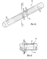
- FIGS 9A-9C illustrate further improvements to enhance the resistance of the vena cava filter against undesired displacement.
- a rib 28 of a vena cava filter according to the present invention has been illustrated, which has been provided with hooking elements 26 and 27 pointing in opposite directions. These hooking elements are sufficiently sized and small so that they ensure the proper grip on the internal wall of the blood vessel, but tend not to damage the latter.
- this embodiment can be manufactured advantageously by providing the tubular basic shape shown in figure 7 with additional notches, as illustrated in figure 10 and indicated with number 31.
- Figure 11 shows a cross-sectional view along the line 11-11 in order to clarify the configuration of the notch 31.
- Figure 12 it has been illustrated that the notched sections of the tubular basic shape 23 bend outward during expansion hereof, to extend hooking elements similar to those indicated with number 27 in figures 9A-C.
- Figure 12A illustrates the situation prior to expansion, and figure 12B the situation immediately following expansion.
- arrow A has been used to indicate the relative directions of sections of the basic shape 23 to the left and the right of the notch 31.
- the notches 31 also provide attenuations in the material of which the basic shape 23 has been made, as a result of which bending is encouraged to occur at the sites of these attenuations.
- FIG 9B a rib 24 of the vena cava filter illustrated in figure 8 is shown.
- a number of hooking elements pointing in opposite directions, have been arranged, which, for the sake of simplicity, have also been given the numbers 26 and 27, whereby a greater number of hooking elements may obviously increase the frictional resistance mentioned above.
- FIG 9C yet another rib 29 is shown, which has been provided with a serrated profile 30, of which the teeth are not arranged in a preset direction but only extend outwards in relation to the vena cava filter, when in use, towards the internal wall of the blood vessel. Also, simple coarsening of the surface of the ribs concerned may suffice.
- Each of the embodiments illustrated in the figures 9A-9c aims at increasing the reliability of the anchoring of the filter, so that the vena cava filter according to the present invention will not shift position. Protrusions such as the projections 26 or 27 or the serrated profile 30 are pushed, due to the elasticity and the tendency of the vena cava filter to expand, into the internal wall of a blood vessel. Consequently, resistance against possible displacement under the influence of the flow of fluid or blood through the blood vessel is increased, and as a result the reliability is enhanced.
- the filter sections on either side of the ribs of the vena cava filters according to the present invention described above display diamond or polygon shapes. It is also possible to suffice with vena cava filters of which the filter sections display in axial view a star shape (as illustrated in figure 5), or any other shape as long as they intercept blood clots or thrombus successfully.
- An advantage of this feature is that, after passing the first filter section and the tubular section or the elongated body member, a second chance at interception in the form of an additional filter section has been provided.
- other shapes of the filter sections in axial view are possible, which shapes will occur to those skilled in the field after reading the present description.
- the shapes of the filter sections in axial view need not be symmetrical, and may have in principle any suitable appearance.
- a vena cava filter according to the present invention may be provided on one or both ends with a noose construction in order to extract the vena cava filter back into a catheter, by means of a hook member.
- the step employing an expandable mold in order to effect the required shape of the vena cava filter has been described each time. It should be noted however, that it is also possible to use a mold which retains its shape, around which in advance sections, deformed under the influence of heat, have been arranged and if desired followed by a step including heating certain sections to such an extent that a vena cava filter, forming one single unit, is manufactured. In this respect one can think of using separate strips, which are arranged around a pill or cigar-shaped mold of the desired shape after heating the latter, in order to connect at least the tips to one another by melting them together.
- Treatment for instance heat treatment, only serves to fix the vena cava filter, and in particular sections hereof, in the new shape defined by the mold.
- This last alternative is particularly suitable for materials which are very elastic, like nitinol.
- vena cava filter In addition to the nitinol mentioned so far, many other materials may also be used for manufacturing a vena cava filter according to the present invention.
- various metals may for instance be used, in which case it is essential that the vena cava filter assumes the intended shape hereof after having been ejected from the catheter for the purpose of introduction hereof.
- the vena cava filter, during introduction, is of course kept in a folded state, by means of the catheter. To this end a configuration may be used decompressing the filter metal due to the elastic properties hereof.
- Vena cava filters according to the invention may for instance be anchored by means of a cord body, in which case this cord body is arranged at a site which can easily be reached from outside the body of a patient, so that removal can take place with a minimum of effort.
- the subject of the invention it is therefore of no consequence whether the filter is placed permanently, in a removable manner, temporarily or otherwise.
Landscapes
- Health & Medical Sciences (AREA)
- Cardiology (AREA)
- Oral & Maxillofacial Surgery (AREA)
- Transplantation (AREA)
- Engineering & Computer Science (AREA)
- Biomedical Technology (AREA)
- Heart & Thoracic Surgery (AREA)
- Vascular Medicine (AREA)
- Life Sciences & Earth Sciences (AREA)
- Animal Behavior & Ethology (AREA)
- General Health & Medical Sciences (AREA)
- Public Health (AREA)
- Veterinary Medicine (AREA)
- Surgical Instruments (AREA)
- Prostheses (AREA)
Abstract
Description
- The present invention relates to a vascular filter which can be temporarily placed inside a blood vessel for the purpose of intercepting thrombus.
- Some basic types of vascular filters are generally known, e.g. from US-A-5.234.458, the disclosure of which is reflected in the pre-characterising portion of claim 1, wherein at least one single filter element or member extends substantially transverse to the direction of flow inside the blood vessel, and is wedged against the blood vessel wall due to the fact that it has a dimension slightly larger than the inside diameter of the blood vessel. Vascular filters may often be used in the vena cava, and may be described in such event as a"vena cava filter."
- Known vascular filters may have some disadvantages, some of which may relate to their reliability. As such, known vascular filters may consist of a network of interconnected ribs, which extend substantially in a radial direction in relation to the blood vessel. In the filters known from US-A-5.234.458 the ribs also extend longitudinally from the distal to the proximal ends (or vice versa) of the filter, and are intermediately bent outwards radially to provide the filter function.
- Unfortunately, the entire filter may shift position if one of the ribs breaks. In addition, the free ends of the ribs, which are positioned under a certain pressure against the internal wall of the blood vessel, may cause trauma to the vessel wall, or may become embedded in it which may involve risk for the patient.
- Another disadvantage of known vascular filters may be a possibility of shifting position in the blood flow inside the blood vessel, even when the filter maintains its proper shape, if a known vascular filter may have been incorrectly placed in a portion of the blood vessel which is too wide. In such an event, a vascular filter may not grab sufficient hold on the internal wall of the blood vessel.
- Accordingly, an object of the present invention is to provide a vascular filter for delivery through a catheter in a compressed shape, where it tends to resiliently expand within the blood vessel. The vascular filter tends to trap thrombus or particles, and resist their movement further downstream. The filter includes, in a position of use, a circumference corresponding to the internal diameter of the blood vessel transverse to the longitudinal direction hereof. Filters according to the present invention are distinguished over the prior art of e.g. US-A-5.234.458 by the features defined in the characterising portion of claim 1.
- With a vascular filter according to the present invention, the tubular section tends to wedge itself in place within the blood vessel, exerting pressure locally, along a large section of contact area, on the wall of the blood vessel. Accordingly, the filter tends to exert pressure on the internal wall of the blood vessel which could result in perforation of the blood vessel, but tends to hold itself in place. The vascular filter will consequently tend not to shift position.
- In addition, the vascular filter according to the present invention cannot rotate transversely or tilt over, which is another important advantage of the present invention. In a preferred embodiment, a vascular filter according to the present invention has preferably been formed out of one single piece, which provides advantages, including simplicity.
- The vascular filter according to the present invention includes a first and second filter section, arrange on either side of a body member. The body member and the filter sections thus enclose a space. Due to the elongated shape of the vascular filter according to the present invention, and the arranging of the first and second section on either side of the body member, the present filter has an enhanced filtering effect.
- In other words, two opportunities have been created for intercepting thrombus moving inside the blood vessel. The position of the filter inside the vena cava or another the blood vessel is therefore not dependent on the route along which it has been introduced, as a result of which the physician concerned has more freedom when choosing a route for introducing the vascular filter.
- A vena cava filter according to the present invention incorporates the feature that, when seen in an axial direction, the passage has the shape of a regular polygon, and provides several smaller filtering "cells". The purpose of these filtering cells is to intercept thrombus moving inside the blood vessel.
- The filter sections, as arranged according to an embodiment described above on either side of the tubular body section, are preferably identical in shape, thereby enhancing the simplicity of the vascular filter according to the present invention.
- A vascular filter may have been made of a braiding of wire-like elements, or a single plate-like element having a series of cuts at places corresponding to the positions of passages, or a tubular element also having a series of cuts at places corresponding to the positions of passages. It is thus preferably possible to effect under the influence of heat at least deformation of the material and possibly expansion of the vascular filter, which may be made in one of three ways mentioned, to obtain the ultimate shape and in particular the circumference hereof. Possible junctions are preferably effected by melting or welding free ends together, or by employing such a cutting pattern that the basic shape of the vascular filter according to the present invention is obtained. In addition, an advantage of the filter made of a tubular body is that it can be reduced to the dimensions of the tubular body, which dimensions may be very small, so that also the dimensions of the catheter required to introduce the filter may be very small.
- It should be noted that the present invention also relates to methods for manufacturing vascular filters as described herein.
- These and various other objects, advantages and features of the invention will become apparent from the following description and claims, when considered in conjunction with the appended drawings.
- The invention will be explained in greater detail below with reference to the attached drawings of a number of examples of embodiments hereof.
-
- Figure 1 shows a perspective view of a vascular filter in a position of use, and also illustrates schematically a manner in which the vascular filter may be placed inside a blood vessel;
- Figures 2 and 3 illustrate schematically preferable steps in the manufacturing of a second vascular filter according to the method of present invention;
- Figure 4 shows a perspective view of a vascular filter made according to the method of the present invention, prior to being used; and
- Figure 5 shows a perspective view of a vascular filter illustrated in Figure 4 when in use;
- Figure 6 shows a view of planar element for the manufacturing of a vascular filter according to the present invention;
- Figure 7 shows an alternative embodiment for the production of the vascular filter of Figure 6 out of a tubular shape according to the present invention and
- Figure 8 shows a perspective view of the vascular filter of Figure 6 according to the present invention;
- Figures 9A-9C are detailed views of portions of a vascular filter having hooks or friction members, according to the present invention;
- Figure 10 shows a perspective view corresponding to another embodiment of the present invention; and
- Figures 11 and 12 A-B show cross-sectional views of the embodiment illustrated in figure 10.
-
- The following description of the preferred embodiments of the present invention is merely illustrative in nature, and as such it does not limit in any way the present invention, its application, or uses. Numerous modifications may be made by those skilled in the art without departing from the scope of the invention as defined by the appended claims.
- In Figure 1 a vascular filter 1 according to the present invention has been shown. In the situation illustrated here, the vena cava filter 1 has just been introduced into a blood vessel 2 by means of a catheter 3, which is substantially hollow and in which at least one vena cava filter has been arranged, in folded state, in the distal tip 4 hereof. By way of an alternative not illustrated here, it is also possible that the filter is pushed along the entire length of the catheter after the distal end hereof has been advanced to the required position. In this case the filter has preferably been packed in compressed state in transport packaging forming a covering. The vena cava filter is ejected by means of a pushing wire 5 from the distal tip 4 of the catheter 3 and is introduced into the blood vessel where, due to the absence of the spacial limitation effective in the distal tip 4 of the catheter 3, the vena cava filter 1 will expand, under the influence of expansive forces inherent to the material of which the vena cava filter 1 has been made, into the shape illustrated here.
- The vena cava filter illustrated here comprises a number of
ribs 6 extending in an axial direction in relation to the blood vessel 2 and along the internal wall hereof. Theseribs 6 form an elongated body member. On either side of theribs 6, filters 7 have been arranged each forming a grid shape. Liquid inside the blood vessel can pass through in an unimpeded fashion, but thrombus are intercepted by one of the two filters 7. - A great advantage of this configuration is that it provides two chances at intercepting thrombus moving inside the blood vessel. In addition, due to the shape of the
ribs 6, which extend along the internal wall of the blood vessel 2, it is ensured that there are no free ends of ribs which may damage the internal wall of the blood vessel 2 and possibly cause a trauma. The configuration of the vena cava filter according to the present invention illustrated is consequently designed so as to cause a minimum of damage to the blood vessel inside of which it is arranged. As the filters 7 have been arranged on either side of theribs 6, a longitudinally symmetrical shape has been obtained. Accordingly, there is no difference as regards to whether the vena cava filter 1 is placed forward or backward inside the blood vessel 2. In other words, the proximal and distal ends of the filter are identical - As has been illustrated here clearly, the grid shape of each of the filters 7 is such that each of the
ribs 6 is connected to a number of the components of these filters 7. Furthermore, each of theribs 6 is connected with both filters 7 on either side. Due to this configuration, even in the event that one of theribs 6 or a component of one of the filters 7 may possibly break, the filter will tend not to shift position. - In addition, tipping over of both filters 7 has been avoided effectively due to the more or less tubular shape into which the
ribs 6 have been arranged, so that positioning of the vena cava filter 1 inside the blood vessel 2 can take place with unprecedented stability and reliability. - In addition, the vena cava filter 1 has been made of a very resilient material, like nitinol, so that following deployment from the distal tip 4 of the catheter, it can expand and will be wedged against the internal wall 8 of the blood vessel 2.
- In Figure 2, a
plate 9 for a vena cava filter made according to the method of the invention has been illustrated, which has been made of nitinol, and in which cuts 10 have been arranged. The cuts 10 extend alternately from one of the two sides of theplate 9 over a large section of the width of theplate 9, as has been illustrated in figure 2. When manufacturing a vena cava filter according to the method of the present invention theplate 9 may be pulled apart under the influence of heat and in a deforming manner in such a way that a shape, of which a detail has been illustrated in figure 3, is obtained. Next this drawn out shape illustrated in figure 3 is arranged around a mold with a circular cross section, which mold has not been illustrated here, whereby both the welding strips 11 in figure 2 and the welding strips 12 at theends 13, each of which has been connected to tworibs 6 as illustrated in figure 3, connect to one another respectively. To this end, the length of the mold (not illustrated here) is such that it corresponds to the length of theribs 6 in figure 3 and the mould is consequently pill or cigar shaped allowing in particular the welding strips 12 to connect to one another. Next the welding strips 12 are connected to one another and the welding strips 11 are connected to one another by means of heat treatment in order to make these welding strips 11, 12 melt together respectively. Next, employing a method according to the present invention and whilst heating the configuration illustrated in figure 3 which is to be processed into a vena cava filter, of which the welding strips 11, 12 have been melted together respectively, the mould, not illustrated here and preferably made of a pliable material, is expanded in order to deform the material of which the vena cava filter is to be formed in this manner into a shape of which the central section, that is to say, the section corresponding to theribs 6, has a larger diameter than the tips on either side, that is to say those sections corresponding to the ends 13. - After cooling, the vena cava filter thus formed retains the shape of the expanded (but not illustrated) mold and it will then be possible to fold the vena cava filter thus formed, in order to place it inside the distal tip of a catheter 3 for the purpose of introduction, as has been illustrated in figure 1.
- Using nitinol ensures that the filter is very elastic, while it can be folded so as to occupy only a very limited space and expands independently to the diameter of the blood vessel after introducing it in the manner described above with reference to figure 1.
- Using the mold ensures deformation of the basic shape of the material of which the vena cava filter is made, whereby elasticity of the vena cava filter thus formed manifests itself in relation to this new basic shape.
- In figure 4, a another vena cava 35
filter 15 made according to the method of the present invention has been illustrated in the state just prior to introduction into a blood vessel hereof. Thevena cava filter 15 has been folded around aguidewire 14, whereby thevena cava filter 15 is freely movable along theguidewire 14. In figure 4, the catheter body itself has not been shown, but it is noted that the vena cava filter remains in the folded state illustrated here due to the space limiting effect exerted by the distal tip of this catheter body, inside of which thevena cava filter 15 is situated in its folded state. - The
vena cava filter 15 comprisescuts 16 extending in the longitudinal direction of thevena cava filter 15 between, but not as far as the ends of this vena cava filter. By means of the cuts, strips ofmaterial 18 have been defined, as illustrated in figure 5, which is an illustration of thevena cava filter 15 just following ejection from the catheter not illustrated here and its subsequent expansion. Thesestrips 18 correspond to theribs 6 as illustrated in the figures 1 and 2, but comprise bendinglines 17 which have been defined by the shape of the mold which has been used in the manufacturing process of thevena cava filter 15 illustrated here. Thestrips 18 consequently also form thefilters 30 on either side of thefilter 15. Those sections of thestrips 18 forming the ribs extend in an axial direction and are connected on either side with afilter 30, which is formed between the bendinglines 17 and the tips on either side of thevena cava filter 15. - Also in this case, possible breaking of a section of a
strip 18 functioning as rib, or breaking of a section functioning as filter 7 cannot result in the vena cava filter shirting position which, in the state illustrated in figure 5, is still arranged over theguidewire 14, which is subsequently to be withdrawn after the correct positioning hereof. As long as the vena cava filter has been provided with more than two strips, the filter will tend not to shift position, due to the breaking of one of the strips; especially in the case of a uniform distribution in radial direction of the strips thus provided this is avoided in an effective manner. - The embodiment of the vena cava filter made according to the method of the present invention illustrated here also has the safety advantages of the tendency to prevent any free ends from occurring and damaging the internal wall of a blood vessel, and that these sections of the
strips 18 extend as ribs along the internal wall of the blood vessel. - In figure 6, a
plate 19 for a vascular filter has been illustrated which shows an alternative in relation to the one which has been illustrated in figure 2. Also, thisplate 19 includes cuts, although they are arranged in a different pattern to those in the plate illustrated in figure 2. - The
plate 19 is arranged around an inflatable or expandable mold (not illustrated), the longitudinal direction of which corresponds to the transverse direction of theplate 19 illustrated in figure 6, and the cross-section of which is circular. The welding strips 21 are connected to one another for instance by means of melting them together. Accordingly, thevena cava filter 22 illustrated in figure 8 is obtained following expansion of the mold while heating the material of which theplate 19 has been made. - After melting the welding strips 21 together, a tubular basic shape is obtained, which has been illustrated in figure 7 and is indicated with
reference number 23. In addition, thebasic shape 23 may also be obtained by arranging the pattern ofcuts 20, as shown in thebasic shape 23 in figure 7, in a tubular element which has been made of nitinol for instance. Thus the step of melting the welding strips 21 in figure 6 together is avoided, thus simplifying the procedure of manufacturing the vena cava filter according to the present invention considerably. - The vena cava filter ultimately formed, as illustrated in figure 8, once again comprises
ribs 24, 35 just like the other embodiments of vena cava filters according the present invention illustrated in figure 1 and figure 5. Each of the ribs of thevena cava filter 22 in figure 8 is connected on either side with a number of components offilters 25. The filter thus displaying a grid shape with passages sufficiently large so as not to impede normal flow of liquid through the blood vessel, but small enough to intercept harmful blood clots or thrombus. In doing so, as has been described above, this filtering action occurs at two locations in thevena cava filter 22. In axial view, the passages in the network of thefilters 25 display the shape of a diamond, parallelogram or polygon. - Figures 9A-9C illustrate further improvements to enhance the resistance of the vena cava filter against undesired displacement. In figure 9A for instance, a
rib 28 of a vena cava filter according to the present invention has been illustrated, which has been provided with hookingelements - In particular, this embodiment can be manufactured advantageously by providing the tubular basic shape shown in figure 7 with additional notches, as illustrated in figure 10 and indicated with
number 31. Figure 11 shows a cross-sectional view along the line 11-11 in order to clarify the configuration of thenotch 31. In figure 12 it has been illustrated that the notched sections of the tubularbasic shape 23 bend outward during expansion hereof, to extend hooking elements similar to those indicated withnumber 27 in figures 9A-C. Figure 12A illustrates the situation prior to expansion, and figure 12B the situation immediately following expansion. In figure 12A, arrow A has been used to indicate the relative directions of sections of thebasic shape 23 to the left and the right of thenotch 31. - The
notches 31 also provide attenuations in the material of which thebasic shape 23 has been made, as a result of which bending is encouraged to occur at the sites of these attenuations. - In figure 9B, a
rib 24 of the vena cava filter illustrated in figure 8 is shown. On each of theribs 24, a number of hooking elements, pointing in opposite directions, have been arranged, which, for the sake of simplicity, have also been given thenumbers - In figure 9C yet another
rib 29 is shown, which has been provided with aserrated profile 30, of which the teeth are not arranged in a preset direction but only extend outwards in relation to the vena cava filter, when in use, towards the internal wall of the blood vessel. Also, simple coarsening of the surface of the ribs concerned may suffice. - Each of the embodiments illustrated in the figures 9A-9c aims at increasing the reliability of the anchoring of the filter, so that the vena cava filter according to the present invention will not shift position. Protrusions such as the
projections serrated profile 30 are pushed, due to the elasticity and the tendency of the vena cava filter to expand, into the internal wall of a blood vessel. Consequently, resistance against possible displacement under the influence of the flow of fluid or blood through the blood vessel is increased, and as a result the reliability is enhanced. - In the axial view, the filter sections on either side of the ribs of the vena cava filters according to the present invention described above display diamond or polygon shapes. It is also possible to suffice with vena cava filters of which the filter sections display in axial view a star shape (as illustrated in figure 5), or any other shape as long as they intercept blood clots or thrombus successfully. An advantage of this feature is that, after passing the first filter section and the tubular section or the elongated body member, a second chance at interception in the form of an additional filter section has been provided. Also, other shapes of the filter sections in axial view are possible, which shapes will occur to those skilled in the field after reading the present description. The shapes of the filter sections in axial view need not be symmetrical, and may have in principle any suitable appearance.
- If it is desirable to be able to remove a vena cava filter introduced into a blood vessel at a later stage, a vena cava filter according to the present invention may be provided on one or both ends with a noose construction in order to extract the vena cava filter back into a catheter, by means of a hook member.
- Furthermore, in connection with the method for manufacturing a vena cava filter according to the present invention, the step employing an expandable mold in order to effect the required shape of the vena cava filter has been described each time. It should be noted however, that it is also possible to use a mold which retains its shape, around which in advance sections, deformed under the influence of heat, have been arranged and if desired followed by a step including heating certain sections to such an extent that a vena cava filter, forming one single unit, is manufactured. In this respect one can think of using separate strips, which are arranged around a pill or cigar-shaped mold of the desired shape after heating the latter, in order to connect at least the tips to one another by melting them together. Furthermore, it is not necessary to deform sections of the vena cava filter in advance. Treatment, for instance heat treatment, only serves to fix the vena cava filter, and in particular sections hereof, in the new shape defined by the mold. This last alternative is particularly suitable for materials which are very elastic, like nitinol.
- In addition to the nitinol mentioned so far, many other materials may also be used for manufacturing a vena cava filter according to the present invention. By way of alternative, various metals may for instance be used, in which case it is essential that the vena cava filter assumes the intended shape hereof after having been ejected from the catheter for the purpose of introduction hereof. The vena cava filter, during introduction, is of course kept in a folded state, by means of the catheter. To this end a configuration may be used decompressing the filter metal due to the elastic properties hereof.
- Furthermore, retraction of a vena cava filter according to the present invention is mentioned above, which should not limit the scope of the claims attached. Vena cava filters according to the invention may for instance be anchored by means of a cord body, in which case this cord body is arranged at a site which can easily be reached from outside the body of a patient, so that removal can take place with a minimum of effort. As regards the subject of the invention it is therefore of no consequence whether the filter is placed permanently, in a removable manner, temporarily or otherwise.
Claims (5)
- A vascular filter (1), which can be placed inside a blood vessel and which comprises:characterised in thatin a radially compressed state, a tubular metal cylinder having a first and second integral cylindrical end collar (7) at a proximal and a distal end of the vascular filter; a plurality of ribs (6) arranged in a preselected pattern and extending between the first and second end collar in a direction parallel to a longitudinal axis of the vascular filter;in radially expanded deployed state, the ribs tend to resiliently expand in radial directions, thereby causing the first and second end collars to move toward each other; each of the ribs tending to spread apart,whereby the first and second filter sections enhance the effectiveness of the vascular filter.in the radially expanded state the vascular filter defines a plurality of central parallel hexagon shapes arranged adjacently around a central circumference of the vascular filter, each of the ribs defining each hexagon shape extending in a plane parallel to the longitudinal axis of the vascular filter;the vascular filter further defining a first and second end filter portion connecting the central hexagons with the end collars, wherein the end filter portions each define a plurality of diamond shaped sections having four sides;each of the diamond shapes being formed by a first and second rib each forming a portion of a first and second of the central hexagon shapes, and by a first and second conical rib directly connecting an apex of the first and second of the central hexagon shapes with the end collars respectively;the conical ribs all extending along a first and second end cone;
- The vascular filter as claimed in claim 1, characterized in that the construction is such that it has been formed out of one single unitary metal element (9, 15, 19, 23).
- The vascular filter as claimed in Claim 1, adapted for use in the vena cava.
- The vascular filter as claimed in one of the previous claims, characterized by anchors (26, 27, 30) formed on at least one surface of the vascular filter directed outward in a radial direction.
- A method for manufacturing a vascular filter comprising forming an cylindrical elongated body member out of one single element having a first and second unitary cylindrical end collar, and a plurality of structural ribs formed by a series of longitudinal cuts (20) in the cylindrical body member with, in a position of use, a circumference corresponding to the internal diameter of the blood vessel and having a first and second conical end filter section for collecting and trapping thrombus, and forming the cuts such that in the radially expanded state the vascular filter defines a plurality of central parallel hexagon shapes arranged adjacently around a central circumference of the vascular filter.
Applications Claiming Priority (3)
| Application Number | Priority Date | Filing Date | Title |
|---|---|---|---|
| NL1007584A NL1007584C2 (en) | 1997-11-19 | 1997-11-19 | Vena cava filter. |
| NL1007584 | 1997-11-19 | ||
| PCT/US1998/024305 WO1999025252A1 (en) | 1997-11-19 | 1998-11-13 | Vascular filter |
Publications (3)
| Publication Number | Publication Date |
|---|---|
| EP1032311A1 EP1032311A1 (en) | 2000-09-06 |
| EP1032311A4 EP1032311A4 (en) | 2002-04-17 |
| EP1032311B1 true EP1032311B1 (en) | 2005-01-26 |
Family
ID=19766041
Family Applications (1)
| Application Number | Title | Priority Date | Filing Date |
|---|---|---|---|
| EP98959449A Expired - Lifetime EP1032311B1 (en) | 1997-11-19 | 1998-11-13 | Vascular filter |
Country Status (5)
| Country | Link |
|---|---|
| EP (1) | EP1032311B1 (en) |
| CA (1) | CA2311291C (en) |
| DE (1) | DE69828814T2 (en) |
| NL (1) | NL1007584C2 (en) |
| WO (1) | WO1999025252A1 (en) |
Families Citing this family (129)
| Publication number | Priority date | Publication date | Assignee | Title |
|---|---|---|---|---|
| US6974469B2 (en) | 1997-03-06 | 2005-12-13 | Scimed Life Systems, Inc. | Distal protection device and method |
| US7094249B1 (en) | 1997-03-06 | 2006-08-22 | Boston Scientific Scimed, Inc. | Distal protection device and method |
| US6676682B1 (en) | 1997-05-08 | 2004-01-13 | Scimed Life Systems, Inc. | Percutaneous catheter and guidewire having filter and medical device deployment capabilities |
| US7491216B2 (en) | 1997-11-07 | 2009-02-17 | Salviac Limited | Filter element with retractable guidewire tip |
| IE980920A1 (en) | 1997-11-07 | 1999-05-19 | Salviac Ltd | An embolic protection device |
| US7314477B1 (en) | 1998-09-25 | 2008-01-01 | C.R. Bard Inc. | Removable embolus blood clot filter and filter delivery unit |
| US7044134B2 (en) | 1999-11-08 | 2006-05-16 | Ev3 Sunnyvale, Inc | Method of implanting a device in the left atrial appendage |
| US6398803B1 (en) * | 1999-02-02 | 2002-06-04 | Impra, Inc., A Subsidiary Of C.R. Bard, Inc. | Partial encapsulation of stents |
| US6171327B1 (en) | 1999-02-24 | 2001-01-09 | Scimed Life Systems, Inc. | Intravascular filter and method |
| AU3844499A (en) | 1999-05-07 | 2000-11-21 | Salviac Limited | Improved filter element for embolic protection device |
| US6964672B2 (en) | 1999-05-07 | 2005-11-15 | Salviac Limited | Support frame for an embolic protection device |
| US6918921B2 (en) | 1999-05-07 | 2005-07-19 | Salviac Limited | Support frame for an embolic protection device |
| US7014647B2 (en) | 1999-05-07 | 2006-03-21 | Salviac Limited | Support frame for an embolic protection device |
| US20030150821A1 (en) | 1999-07-16 | 2003-08-14 | Bates Mark C. | Emboli filtration system and methods of use |
| US6468291B2 (en) * | 1999-07-16 | 2002-10-22 | Baff Llc | Emboli filtration system having integral strut arrangement and methods of use |
| US7306618B2 (en) | 1999-07-30 | 2007-12-11 | Incept Llc | Vascular device for emboli and thrombi removal and methods of use |
| US6544279B1 (en) | 2000-08-09 | 2003-04-08 | Incept, Llc | Vascular device for emboli, thrombus and foreign body removal and methods of use |
| US7320697B2 (en) | 1999-07-30 | 2008-01-22 | Boston Scientific Scimed, Inc. | One piece loop and coil |
| US6142987A (en) | 1999-08-03 | 2000-11-07 | Scimed Life Systems, Inc. | Guided filter with support wire and methods of use |
| US6235044B1 (en) | 1999-08-04 | 2001-05-22 | Scimed Life Systems, Inc. | Percutaneous catheter and guidewire for filtering during ablation of mycardial or vascular tissue |
| US6217589B1 (en) | 1999-10-27 | 2001-04-17 | Scimed Life Systems, Inc. | Retrieval device made of precursor alloy cable and method of manufacturing |
| US6994092B2 (en) * | 1999-11-08 | 2006-02-07 | Ev3 Sunnyvale, Inc. | Device for containing embolic material in the LAA having a plurality of tissue retention structures |
| US6371971B1 (en) * | 1999-11-15 | 2002-04-16 | Scimed Life Systems, Inc. | Guidewire filter and methods of use |
| FR2801493B1 (en) | 1999-11-26 | 2003-10-03 | Braun Celsa Sa | METHOD FOR MANUFACTURING A MONOBLOCK BLOOD FILTER |
| US9113936B2 (en) * | 1999-12-23 | 2015-08-25 | Abbott Laboratories | Snare |
| US6540767B1 (en) * | 2000-02-08 | 2003-04-01 | Scimed Life Systems, Inc. | Recoilable thrombosis filtering device and method |
| GB2369575A (en) | 2000-04-20 | 2002-06-05 | Salviac Ltd | An embolic protection system |
| EP1153581B1 (en) * | 2000-05-09 | 2004-07-14 | EndoArt S.A. | Vascular implant comprising a central deflector |
| US6565591B2 (en) | 2000-06-23 | 2003-05-20 | Salviac Limited | Medical device |
| US7169165B2 (en) | 2001-01-16 | 2007-01-30 | Boston Scientific Scimed, Inc. | Rapid exchange sheath for deployment of medical devices and methods of use |
| US6936059B2 (en) | 2001-01-16 | 2005-08-30 | Scimed Life Systems, Inc. | Endovascular guidewire filter and methods of use |
| US6663651B2 (en) | 2001-01-16 | 2003-12-16 | Incept Llc | Systems and methods for vascular filter retrieval |
| US6689151B2 (en) | 2001-01-25 | 2004-02-10 | Scimed Life Systems, Inc. | Variable wall thickness for delivery sheath housing |
| US6840950B2 (en) | 2001-02-20 | 2005-01-11 | Scimed Life Systems, Inc. | Low profile emboli capture device |
| US20020123755A1 (en) | 2001-03-01 | 2002-09-05 | Scimed Life Systems, Inc. | Embolic protection filter delivery sheath |
| US7226464B2 (en) | 2001-03-01 | 2007-06-05 | Scimed Life Systems, Inc. | Intravascular filter retrieval device having an actuatable dilator tip |
| US6537295B2 (en) | 2001-03-06 | 2003-03-25 | Scimed Life Systems, Inc. | Wire and lock mechanism |
| EP1238639B1 (en) | 2001-03-07 | 2006-06-07 | Bavaria Medizin Technologie GmbH | Filter device for vessel systems |
| US7179275B2 (en) | 2001-06-18 | 2007-02-20 | Rex Medical, L.P. | Vein filter |
| US6951570B2 (en) | 2001-07-02 | 2005-10-04 | Rubicon Medical, Inc. | Methods, systems, and devices for deploying a filter from a filter device |
| US6997939B2 (en) | 2001-07-02 | 2006-02-14 | Rubicon Medical, Inc. | Methods, systems, and devices for deploying an embolic protection filter |
| US6962598B2 (en) | 2001-07-02 | 2005-11-08 | Rubicon Medical, Inc. | Methods, systems, and devices for providing embolic protection |
| US8262689B2 (en) * | 2001-09-28 | 2012-09-11 | Advanced Cardiovascular Systems, Inc. | Embolic filtering devices |
| US6755847B2 (en) | 2001-10-05 | 2004-06-29 | Scimed Life Systems, Inc. | Emboli capturing device and method of manufacture therefor |
| US6887257B2 (en) | 2001-10-19 | 2005-05-03 | Incept Llc | Vascular embolic filter exchange devices and methods of use thereof |
| US7052500B2 (en) | 2001-10-19 | 2006-05-30 | Scimed Life Systems, Inc. | Embolus extractor |
| JP4350515B2 (en) | 2001-11-09 | 2009-10-21 | ルビコン・メデイカル・インコーポレイテツド | Stent delivery device |
| US7153320B2 (en) | 2001-12-13 | 2006-12-26 | Scimed Life Systems, Inc. | Hydraulic controlled retractable tip filter retrieval catheter |
| US6793666B2 (en) | 2001-12-18 | 2004-09-21 | Scimed Life Systems, Inc. | Distal protection mechanically attached filter cartridge |
| WO2003055413A2 (en) | 2001-12-21 | 2003-07-10 | Salviac Limited | A support frame for an embolic protection device |
| US6932830B2 (en) | 2002-01-10 | 2005-08-23 | Scimed Life Systems, Inc. | Disc shaped filter |
| US6997938B2 (en) | 2002-02-12 | 2006-02-14 | Scimed Life Systems, Inc. | Embolic protection device |
| US9204956B2 (en) | 2002-02-20 | 2015-12-08 | C. R. Bard, Inc. | IVC filter with translating hooks |
| US7118539B2 (en) | 2002-02-26 | 2006-10-10 | Scimed Life Systems, Inc. | Articulating guide wire for embolic protection and methods of use |
| DE60315425T2 (en) | 2002-03-05 | 2008-06-26 | Salviac Ltd. | SYSTEM FOR PROTECTION FROM EMBOLICS |
| US7029440B2 (en) | 2002-03-13 | 2006-04-18 | Scimed Life Systems, Inc. | Distal protection filter and method of manufacture |
| US7060082B2 (en) | 2002-05-06 | 2006-06-13 | Scimed Life Systems, Inc. | Perfusion guidewire in combination with a distal filter |
| US7585309B2 (en) | 2002-05-16 | 2009-09-08 | Boston Scientific Scimed, Inc. | Aortic filter |
| US7001406B2 (en) | 2002-05-23 | 2006-02-21 | Scimed Life Systems Inc. | Cartridge embolic protection filter and methods of use |
| US7326224B2 (en) | 2002-06-11 | 2008-02-05 | Boston Scientific Scimed, Inc. | Shaft and wire lock |
| DE10233085B4 (en) | 2002-07-19 | 2014-02-20 | Dendron Gmbh | Stent with guide wire |
| US8425549B2 (en) | 2002-07-23 | 2013-04-23 | Reverse Medical Corporation | Systems and methods for removing obstructive matter from body lumens and treating vascular defects |
| US7115138B2 (en) | 2002-09-04 | 2006-10-03 | Boston Scientific Scimed, Inc. | Sheath tip |
| US7174636B2 (en) | 2002-09-04 | 2007-02-13 | Scimed Life Systems, Inc. | Method of making an embolic filter |
| US8468678B2 (en) | 2002-10-02 | 2013-06-25 | Boston Scientific Scimed, Inc. | Expandable retrieval device |
| AU2011232786B2 (en) * | 2002-10-17 | 2015-02-26 | W. L. Gore & Associates, Inc. | Embolic filter frame having looped support strut elements |
| US20040093012A1 (en) | 2002-10-17 | 2004-05-13 | Cully Edward H. | Embolic filter frame having looped support strut elements |
| US7481823B2 (en) | 2002-10-25 | 2009-01-27 | Boston Scientific Scimed, Inc. | Multiple membrane embolic protection filter |
| US6989021B2 (en) * | 2002-10-31 | 2006-01-24 | Cordis Corporation | Retrievable medical filter |
| US7625389B2 (en) | 2002-12-30 | 2009-12-01 | Boston Scientific Scimed, Inc. | Embolic protection device |
| US7163549B2 (en) | 2003-02-11 | 2007-01-16 | Boston Scientific Scimed Inc. | Filter membrane manufacturing method |
| US7137991B2 (en) | 2003-02-24 | 2006-11-21 | Scimed Life Systems, Inc. | Multi-wire embolic protection filtering device |
| US7740644B2 (en) | 2003-02-24 | 2010-06-22 | Boston Scientific Scimed, Inc. | Embolic protection filtering device that can be adapted to be advanced over a guidewire |
| US6878291B2 (en) | 2003-02-24 | 2005-04-12 | Scimed Life Systems, Inc. | Flexible tube for cartridge filter |
| US7163550B2 (en) | 2003-03-26 | 2007-01-16 | Scimed Life Systems, Inc. | Method for manufacturing medical devices from linear elastic materials while maintaining linear elastic properties |
| US6960370B2 (en) | 2003-03-27 | 2005-11-01 | Scimed Life Systems, Inc. | Methods of forming medical devices |
| US6902572B2 (en) | 2003-04-02 | 2005-06-07 | Scimed Life Systems, Inc. | Anchoring mechanisms for intravascular devices |
| WO2004098459A1 (en) * | 2003-04-30 | 2004-11-18 | Rex Medical, L.P. | Vein filter |
| US7780611B2 (en) | 2003-05-01 | 2010-08-24 | Boston Scientific Scimed, Inc. | Medical instrument with controlled torque transmission |
| US6969396B2 (en) | 2003-05-07 | 2005-11-29 | Scimed Life Systems, Inc. | Filter membrane with increased surface area |
| US7537600B2 (en) | 2003-06-12 | 2009-05-26 | Boston Scientific Scimed, Inc. | Valved embolic protection filter |
| US9301829B2 (en) | 2003-07-30 | 2016-04-05 | Boston Scientific Scimed, Inc. | Embolic protection aspirator |
| US9510929B2 (en) | 2004-01-22 | 2016-12-06 | Argon Medical Devices, Inc. | Vein filter |
| US7338512B2 (en) | 2004-01-22 | 2008-03-04 | Rex Medical, L.P. | Vein filter |
| US8162972B2 (en) | 2004-01-22 | 2012-04-24 | Rex Medical, Lp | Vein filter |
| US8500774B2 (en) | 2004-01-22 | 2013-08-06 | Rex Medical, L.P. | Vein filter |
| US7704266B2 (en) | 2004-01-22 | 2010-04-27 | Rex Medical, L.P. | Vein filter |
| US7976562B2 (en) | 2004-01-22 | 2011-07-12 | Rex Medical, L.P. | Method of removing a vein filter |
| US7473265B2 (en) | 2004-03-15 | 2009-01-06 | Boston Scientific Scimed, Inc. | Filter media and methods of manufacture |
| EP1735043B1 (en) * | 2004-04-15 | 2011-02-02 | Cordis Corporation | Long-term retrievable medical filter |
| US8801746B1 (en) | 2004-05-04 | 2014-08-12 | Covidien Lp | System and method for delivering a left atrial appendage containment device |
| US7704267B2 (en) | 2004-08-04 | 2010-04-27 | C. R. Bard, Inc. | Non-entangling vena cava filter |
| ES2444590T3 (en) | 2004-09-27 | 2014-02-25 | Rex Medical, L.P. | Venous filter |
| US7621904B2 (en) | 2004-10-21 | 2009-11-24 | Boston Scientific Scimed, Inc. | Catheter with a pre-shaped distal tip |
| US7478465B1 (en) | 2005-01-10 | 2009-01-20 | Boston Scientific Scimed, Inc. | Method of securing a restraining member on a medical device |
| US7204464B2 (en) | 2005-01-21 | 2007-04-17 | Boston Scientific Scimed, Inc. | Medical wire holder |
| US8480629B2 (en) | 2005-01-28 | 2013-07-09 | Boston Scientific Scimed, Inc. | Universal utility board for use with medical devices and methods of use |
| US12115057B2 (en) | 2005-05-12 | 2024-10-15 | C.R. Bard, Inc. | Tubular filter |
| WO2006124405A2 (en) | 2005-05-12 | 2006-11-23 | C.R. Bard Inc. | Removable embolus blood clot filter |
| JP4851522B2 (en) | 2005-08-09 | 2012-01-11 | シー・アール・バード・インコーポレーテッド | Insertion type thrombus filter and delivery system |
| US7972359B2 (en) | 2005-09-16 | 2011-07-05 | Atritech, Inc. | Intracardiac cage and method of delivering same |
| JP2009519731A (en) | 2005-11-18 | 2009-05-21 | シー・アール・バード・インコーポレイテツド | Vena cava filter with filament |
| US10188496B2 (en) | 2006-05-02 | 2019-01-29 | C. R. Bard, Inc. | Vena cava filter formed from a sheet |
| US9326842B2 (en) | 2006-06-05 | 2016-05-03 | C. R . Bard, Inc. | Embolus blood clot filter utilizable with a single delivery system or a single retrieval system in one of a femoral or jugular access |
| US10076401B2 (en) | 2006-08-29 | 2018-09-18 | Argon Medical Devices, Inc. | Vein filter |
| US11337714B2 (en) | 2007-10-17 | 2022-05-24 | Covidien Lp | Restoring blood flow and clot removal during acute ischemic stroke |
| US8088140B2 (en) | 2008-05-19 | 2012-01-03 | Mindframe, Inc. | Blood flow restorative and embolus removal methods |
| CN103549986B (en) | 2008-02-22 | 2015-12-09 | 泰科保健集团有限合伙公司 | The thrombosis device agglomerate of removable combination |
| US8945170B2 (en) | 2008-08-18 | 2015-02-03 | Cook Medical Technologies Llc | Occluding device |
| US8444669B2 (en) | 2008-12-15 | 2013-05-21 | Boston Scientific Scimed, Inc. | Embolic filter delivery system and method |
| JP5685253B2 (en) | 2009-07-29 | 2015-03-18 | シー・アール・バード・インコーポレーテッドC R Bard Incorporated | Tubular filter |
| US9039749B2 (en) | 2010-10-01 | 2015-05-26 | Covidien Lp | Methods and apparatuses for flow restoration and implanting members in the human body |
| US8821478B2 (en) | 2011-03-04 | 2014-09-02 | Boston Scientific Scimed, Inc. | Catheter with variable stiffness |
| CN103917169B (en) * | 2011-11-09 | 2016-11-09 | 波士顿科学国际有限公司 | Plugging device |
| US9308007B2 (en) | 2012-08-14 | 2016-04-12 | W. L. Gore & Associates, Inc. | Devices and systems for thrombus treatment |
| US10076399B2 (en) | 2013-09-13 | 2018-09-18 | Covidien Lp | Endovascular device engagement |
| US11432809B2 (en) | 2017-04-27 | 2022-09-06 | Boston Scientific Scimed, Inc. | Occlusive medical device with fabric retention barb |
| EP3790502A1 (en) | 2018-05-09 | 2021-03-17 | Boston Scientific Scimed, Inc. | Pedal access embolic filtering sheath |
| CN112714632B (en) | 2018-08-21 | 2024-08-30 | 波士顿科学医学有限公司 | Barbed protruding member for cardiovascular device |
| CN114126540B (en) | 2019-07-17 | 2026-01-02 | 波士顿科学医学有限公司 | Continuously covered left atrial appendage implant |
| WO2021041831A1 (en) | 2019-08-30 | 2021-03-04 | Boston Scientific Scimed, Inc. | Left atrial appendage implant with sealing disk |
| WO2021195085A1 (en) | 2020-03-24 | 2021-09-30 | Boston Scientific Scimed, Inc. | Medical system for treating a left atrial appendage |
| CN116685276A (en) | 2020-11-30 | 2023-09-01 | 波士顿科学医学有限公司 | Implantable passive average pressure sensor |
| JP7603169B2 (en) | 2021-01-14 | 2024-12-19 | ボストン サイエンティフィック サイムド,インコーポレイテッド | Medical system for treating the left atrial appendage |
| US12383201B2 (en) | 2021-02-03 | 2025-08-12 | Boston Scientific Scimed, Inc. | Medical system for treating a left atrial appendage |
| CN117500445A (en) | 2021-06-22 | 2024-02-02 | 波士顿科学医学有限公司 | left atrial appendage implant |
| EP4678122A3 (en) | 2021-07-08 | 2026-04-01 | Boston Scientific Scimed, Inc. | Left atrial appendage closure device |
| WO2023038929A1 (en) | 2021-09-08 | 2023-03-16 | Boston Scientific Scimed, Inc. | Occlusive implant with multi-sharpness split tip soft tissue anchors |
| US12502178B2 (en) | 2022-08-16 | 2025-12-23 | Boston Scientific Scimed, Inc. | Medical device for occluding a left atrial appendage |
Family Cites Families (5)
| Publication number | Priority date | Publication date | Assignee | Title |
|---|---|---|---|---|
| US4793348A (en) * | 1986-11-15 | 1988-12-27 | Palmaz Julio C | Balloon expandable vena cava filter to prevent migration of lower extremity venous clots into the pulmonary circulation |
| FR2663217B1 (en) * | 1990-06-15 | 1992-10-16 | Antheor | FILTERING DEVICE FOR THE PREVENTION OF EMBOLIES. |
| US5709704A (en) * | 1994-11-30 | 1998-01-20 | Boston Scientific Corporation | Blood clot filtering |
| DE19509464C1 (en) * | 1995-03-20 | 1996-06-27 | Horst J Dr Med Jaeger | Implant for artery or vein, with anchor piece fixed to wall of vessel |
| WO1998002112A1 (en) * | 1996-07-12 | 1998-01-22 | Alain Fouere | Extensible filtering sheath for surgical use for vena cava or large blood vessels |
-
1997
- 1997-11-19 NL NL1007584A patent/NL1007584C2/en not_active IP Right Cessation
-
1998
- 1998-11-13 DE DE69828814T patent/DE69828814T2/en not_active Expired - Lifetime
- 1998-11-13 CA CA002311291A patent/CA2311291C/en not_active Expired - Lifetime
- 1998-11-13 EP EP98959449A patent/EP1032311B1/en not_active Expired - Lifetime
- 1998-11-13 WO PCT/US1998/024305 patent/WO1999025252A1/en not_active Ceased
Also Published As
| Publication number | Publication date |
|---|---|
| EP1032311A4 (en) | 2002-04-17 |
| CA2311291A1 (en) | 1999-05-27 |
| WO1999025252A1 (en) | 1999-05-27 |
| CA2311291C (en) | 2006-08-22 |
| DE69828814T2 (en) | 2006-01-05 |
| EP1032311A1 (en) | 2000-09-06 |
| NL1007584C2 (en) | 1999-05-20 |
| DE69828814D1 (en) | 2005-03-03 |
Similar Documents
| Publication | Publication Date | Title |
|---|---|---|
| US6443972B1 (en) | Vascular filter | |
| CA2311291C (en) | Vascular filter | |
| JP7582720B2 (en) | Thrombectomy Device and Method | |
| US9615909B2 (en) | Removable embolus blood clot filter and filter delivery unit | |
| US4793348A (en) | Balloon expandable vena cava filter to prevent migration of lower extremity venous clots into the pulmonary circulation | |
| EP1464299B1 (en) | Retrievable medical filter | |
| EP2260789B1 (en) | Removable embolus blood clot filter | |
| US9055996B2 (en) | Method of retrieving a blood clot filter | |
| CN104768479B (en) | Multi-Pivot Thrombectomy Device | |
| EP0942767B1 (en) | Atraumatic anchoring and disengagement mechanism for permanent implant device | |
| US6942680B2 (en) | Stiffened balloon catheter for dilatation and stenting | |
| US8133253B2 (en) | Vascular filter with sleeve | |
| US20040087999A1 (en) | Vascular filter with improved anchor or other position retention | |
| EP0794744B1 (en) | Blood clot filter | |
| US10231814B2 (en) | Vena cava filter | |
| EP1987800B1 (en) | Crossover Retrievable Medical Filter | |
| EP2816969B1 (en) | Vascular filter | |
| CN111513811B (en) | An asymmetric three-dimensional helical thrombectomy stent | |
| JP7863946B2 (en) | Thrombectomy device and method | |
| CN110913797A (en) | Vascular filter system and method of deploying and retracting a vascular filter |
Legal Events
| Date | Code | Title | Description |
|---|---|---|---|
| PUAI | Public reference made under article 153(3) epc to a published international application that has entered the european phase |
Free format text: ORIGINAL CODE: 0009012 |
|
| 17P | Request for examination filed |
Effective date: 20000518 |
|
| AK | Designated contracting states |
Kind code of ref document: A1 Designated state(s): BE CH DE FR GB IE IT LI NL |
|
| RAP1 | Party data changed (applicant data changed or rights of an application transferred) |
Owner name: DUERIG, THOMAS W. Owner name: CORDIS CORPORATION |
|
| RIN1 | Information on inventor provided before grant (corrected) |
Inventor name: DUERIG, THOMAS, W. Inventor name: BREEDVELD, HENDRIK, G. Inventor name: BOSMA, GJALT |
|
| A4 | Supplementary search report drawn up and despatched |
Effective date: 20020301 |
|
| AK | Designated contracting states |
Kind code of ref document: A4 Designated state(s): BE CH DE FR GB IE IT LI NL |
|
| RIC1 | Information provided on ipc code assigned before grant |
Free format text: 7A 61F 2/01 A |
|
| RAP1 | Party data changed (applicant data changed or rights of an application transferred) |
Owner name: CORDIS CORPORATION |
|
| 17Q | First examination report despatched |
Effective date: 20031114 |
|
| GRAP | Despatch of communication of intention to grant a patent |
Free format text: ORIGINAL CODE: EPIDOSNIGR1 |
|
| GRAS | Grant fee paid |
Free format text: ORIGINAL CODE: EPIDOSNIGR3 |
|
| GRAA | (expected) grant |
Free format text: ORIGINAL CODE: 0009210 |
|
| AK | Designated contracting states |
Kind code of ref document: B1 Designated state(s): BE CH DE FR GB IE IT LI NL |
|
| REG | Reference to a national code |
Ref country code: GB Ref legal event code: FG4D |
|
| REG | Reference to a national code |
Ref country code: CH Ref legal event code: NV Representative=s name: ARNOLD & SIEDSMA AG Ref country code: CH Ref legal event code: EP |
|
| REG | Reference to a national code |
Ref country code: IE Ref legal event code: FG4D |
|
| REF | Corresponds to: |
Ref document number: 69828814 Country of ref document: DE Date of ref document: 20050303 Kind code of ref document: P |
|
| PLBE | No opposition filed within time limit |
Free format text: ORIGINAL CODE: 0009261 |
|
| STAA | Information on the status of an ep patent application or granted ep patent |
Free format text: STATUS: NO OPPOSITION FILED WITHIN TIME LIMIT |
|
| ET | Fr: translation filed | ||
| 26N | No opposition filed |
Effective date: 20051027 |
|
| REG | Reference to a national code |
Ref country code: FR Ref legal event code: PLFP Year of fee payment: 19 |
|
| REG | Reference to a national code |
Ref country code: FR Ref legal event code: PLFP Year of fee payment: 20 |
|
| PGFP | Annual fee paid to national office [announced via postgrant information from national office to epo] |
Ref country code: NL Payment date: 20171126 Year of fee payment: 20 Ref country code: DE Payment date: 20171129 Year of fee payment: 20 Ref country code: FR Payment date: 20171127 Year of fee payment: 20 |
|
| PGFP | Annual fee paid to national office [announced via postgrant information from national office to epo] |
Ref country code: BE Payment date: 20171127 Year of fee payment: 20 Ref country code: IT Payment date: 20171123 Year of fee payment: 20 Ref country code: CH Payment date: 20171127 Year of fee payment: 20 Ref country code: IE Payment date: 20171129 Year of fee payment: 20 Ref country code: GB Payment date: 20171127 Year of fee payment: 20 |
|
| REG | Reference to a national code |
Ref country code: GB Ref legal event code: 732E Free format text: REGISTERED BETWEEN 20180614 AND 20180620 |
|
| REG | Reference to a national code |
Ref country code: DE Ref legal event code: R071 Ref document number: 69828814 Country of ref document: DE |
|
| REG | Reference to a national code |
Ref country code: NL Ref legal event code: MK Effective date: 20181112 |
|
| REG | Reference to a national code |
Ref country code: CH Ref legal event code: PL |
|
| REG | Reference to a national code |
Ref country code: GB Ref legal event code: PE20 Expiry date: 20181112 |
|
| REG | Reference to a national code |
Ref country code: BE Ref legal event code: MK Effective date: 20181113 |
|
| REG | Reference to a national code |
Ref country code: IE Ref legal event code: MK9A |
|
| PG25 | Lapsed in a contracting state [announced via postgrant information from national office to epo] |
Ref country code: IE Free format text: LAPSE BECAUSE OF EXPIRATION OF PROTECTION Effective date: 20181113 |
|
| PG25 | Lapsed in a contracting state [announced via postgrant information from national office to epo] |
Ref country code: GB Free format text: LAPSE BECAUSE OF EXPIRATION OF PROTECTION Effective date: 20181112 |