EP1032094B1 - Improvements in or relating to mounting terminals with electric wires into connector housings - Google Patents
Improvements in or relating to mounting terminals with electric wires into connector housings Download PDFInfo
- Publication number
- EP1032094B1 EP1032094B1 EP20000301374 EP00301374A EP1032094B1 EP 1032094 B1 EP1032094 B1 EP 1032094B1 EP 20000301374 EP20000301374 EP 20000301374 EP 00301374 A EP00301374 A EP 00301374A EP 1032094 B1 EP1032094 B1 EP 1032094B1
- Authority
- EP
- European Patent Office
- Prior art keywords
- terminals
- terminal
- jig
- cavities
- electric wires
- Prior art date
- Legal status (The legal status is an assumption and is not a legal conclusion. Google has not performed a legal analysis and makes no representation as to the accuracy of the status listed.)
- Expired - Lifetime
Links
Images


Classifications
-
- H—ELECTRICITY
- H01—ELECTRIC ELEMENTS
- H01R—ELECTRICALLY-CONDUCTIVE CONNECTIONS; STRUCTURAL ASSOCIATIONS OF A PLURALITY OF MUTUALLY-INSULATED ELECTRICAL CONNECTING ELEMENTS; COUPLING DEVICES; CURRENT COLLECTORS
- H01R43/00—Apparatus or processes specially adapted for manufacturing, assembling, maintaining, or repairing of line connectors or current collectors or for joining electric conductors
- H01R43/20—Apparatus or processes specially adapted for manufacturing, assembling, maintaining, or repairing of line connectors or current collectors or for joining electric conductors for assembling or disassembling contact members with insulating base, case or sleeve
Definitions
- the present invention concerns improvements in or relating to mounting terminals with electric wires into connector housings.
- the invention has particular, but not exclusive application, for connecting terminals with electric wires and then inserting the terminals with electric wires into connector housings from the back.
- Press-connecting and press-clamping are mainly adopted for connecting electric wires with connector terminals in a wire harness and the like.
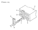
- a press-connecting connection (hereinafter, merely referred to as press-connecting) is shown in Figure 27.
- the press-connecting terminals t are loaded in the cavities s of a connector housing C.
- Press-connecting blade guides 1 are matched with the connector housing C ( Figure 27(a)), and electric wires a are supplied ( Figure 27(b)), and pressed and connected in the terminals t by press-connecting blades 2 ( Figure 27(c)). Namely, the press-connecting presses and loads the electric wires a into a connector housing C from above.
- a press-clamping connection (hereinafter, merely referred to as press-clamping) successively press-clamps the connecting pieces of the terminals on the bare conductors after removing the covering of the electric wires.
- the press-clamping press-clamps the terminals to every electric wire, chucks pick up the terminals one by one with a hand 3 and insert them into the cavities s of the connector housing C from the back (terminal-inserting inlet) as shown in Figure 29 (refer to Japanese Patent Publication (unexamined) Hei No.9-115642 and the like).
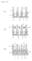
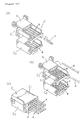
- the connector housing C is conventionally divided into an upper housing C 1 and a lower housing C 2 in order to press the electric-wires in from the upper face of each housing C 1, C 2 as shown in Figure 28.
- cover b is closed and both C 1 and C 2 are integrally connected together (Figure 28(c)) (refer to Japanese Patent Publication (unexamined) Hei No.10-335037 and the like).
- the conventional press-connecting requiring two housings C 1 and C 2 has further many working steps and it causes an increase in cost. Further, the walls e between the cavities may be bent outwards and the housings swollen by pressing power during press-connecting. As a result, it can happen that the cover b is not successfully closed and the upper housing C 2 and the lower housing C 1 are not successfully united. Further, from the viewpoint of reducing the bending problems of the cavity walls e , this type of connector C for press-connecting has terminals t in all of the cavities. However, it was found that mounting terminals t in the cavities s to which electric wires a are not press-connected did not avoid the problems. Further, dismantling of both housings C 1 and C 2 is required for newly press-connecting electric wires a in empty cavities s . As a result the press-connecting is virtually impossible.
- the terminals t with the electric wires a are mounted in the cavities s one by one from the back.
- only one connector housing C (not divided) is required in place of the two stage type connector C as described above.
- the connection of the terminals t one by one is apt to cause a chucking miss.
- the electric wires a are inserted while being held, the electric wires a are apt to buckle as shown by the chain line of Figure 29, and such buckling causes a mounting miss.
- the connector housing C having the cavities s of two stages or more
- the terminals t are inserted in the rotational jig D as shown in Fig.30(b), rolled in the direction of the arrow mark under a condition in which the chucking is released, and chucked again to be inserted in the cavities s as shown in Fig.30(c).
- the rolling action has occasionally the result of causing a twisting power on the electric wires a , and there is a risk that the terminals t cannot be straightforwardly re-chucked and a smooth insertion cannot be obtained.
- US 5 630 273 discloses a holding jig for temporarily holding a plurality of last-in terminals with electric wires attached of a wire harness.
- the holding jig consists of a main body having a plurality of channels thereon for receiving the last-in terminals.
- the channels extend in a direct line from entry apertures for receiving the last-in terminals during loading of the holding jig, to exit apertures, for removing the last-in terminals from the holding jig.
- Resilient means temporarily retain the last-in terminals in the channels and prevent the last-in terminals from being removed from the holding jig via the entry apertures.
- contact members of an insertion jig are pushed through the channels to contact the last-in terminals contained therein pushing the terminals out of the holding jig via the exit apertures.
- the last-in terminals are loaded into the holding jig in the same direction as they are removed from the holding jig.
- the holding jig retains the last-in terminals for continuity testing of the connection before insertion of the last-in terminals into a connector housing.
- PT102 007A discloses an apparatus and method of manufacturing a wiring harness subassembly having both crimp terminals and press-fit terminals.
- the apparatus comprises a cutting stage which cuts wires into desired lengths and a device for press-fitting or crimping terminals held in a connector retaining bar, onto the wires.
- the crimp terminals are removed and inserted into a connector housing.
- the present invention aims to provide a solution to the problems and disadvantages of the known press-connecting and press-clamping connections above-described.
- a process for mounting terminals with electric wires into a connector housing comprising the steps of, loading the terminals into a terminal-connecting jig, connecting the electric wires with the terminals, removing terminals with electric wires from the terminal-connecting jig, and inserting the terminals with electric wires from the back into cavities of the connector housing, characterised by the terminals with electric wires are removed out of the terminal-connecting jig in a direction transverse to a longitudinal direction of the terminals in the terminal-connecting jig by pins of a pushing-out jig pushed through holes below the terminals in the terminal connecting jig.
- the electric wires can be loaded from the upper surface of the jig for press-connecting in like manner to the conventional process. In this way, the press connecting terminals with electric wires can be obtained by press-connecting without any trouble.
- the press-connecting terminals with electric wires are removed from the terminal-connecting jigs and loaded in the connector housing, the press-connecting terminals can be inserted in the cavities of the connector housing from the back in like manner to the press-clamping terminals of Figure 29, and workability is beautiful.
- press-clamping is carried out in place of press-connecting, for example, if press-clamping terminals are loaded in the jigs and the electric wires, after peeling, are press-clamped on the terminals, the press-clamping terminals can be inserted in the connector housing according to a similar action, and workability is again spectacular.
- each terminal with electric wire is removed by one pin of the pushing-out jig.
- each terminal with electric wire is removed by two pins which contact the terminal in the longitudinal direction before and behind the electric wire connecting area.
- the steps of loading the terminals into the terminal connecting jig, connecting the electric wires with the terminals, removing the terminals with the wires from the terminal-connecting jig, and inserting the terminals with electric wires from the back into cavities of the connector housing are sequentially carried out automatically.
- the housing has two stages, an upper stage and a lower stage
- the housing is preferably rolled (inverted) for inserting the terminals with electric wires from the back into cavities of the upper and lower stages.
- the terminals with electric wires may conveniently be loaded into cavities in the connecting jig and are preferably prevented from falling out by protrusions on spring plates below the cavities.
- the terminals are loaded into the cavities from the front of the terminal-connecting jig and a plate at the rear of the terminal-connecting jig assists in positioning of the terminals in the cavities by abutment of the terminals.
- the terminals with electric wires are transferred to a terminal-inserting jig from the terminal-connecting jig, and the terminals with electric wires are inserted into the cavities of the connector housing from the terminal-inserting jig.
- the terminals with electric wires are transferred from the terminal-connecting jig to cavities in the terminal-inserting jig and are preferably prevented from falling out of the cavities by a shutter.
- the terminals may conveniently be guided when pushed out of the inserting jig by guides on the shutter and a clearance is preferably provided in the shutter for the pins.
- the terminals with electric wires are guided when transferred to the inserting jig by transfer guides on both sides of the cavities.
- the terminals with electric wires are transferred from the inserting jig to the cavities of the connector housing by members which push out the terminals in the longitudinal direction and support rear end faces of the terminals.
- the members may have holes therethrough and lock pins may be passed through the members to lock the members into a position so as each member protrudes by a requisite length and only selected members push the terminals into the cavities of the connector housing.
- a method of mounting terminals with electric wires into connector housings comprises the steps of:-
- a system for mounting terminals with electric wires in a connector housing comprising electric wire-measuring and wire-connecting machines for connecting wires to the terminals, characterised in that the system further comprises a mounting machine for mounting the terminals on a terminal-connecting jig, and a terminal-mounting machine for removing the terminals with electric wires from the terminal connecting jig and inserting the terminals with electric wires from the back into cavities of the connector housing, wherein pins of a pushing out jig are arranged to be pushed through holes in the terminal connecting jig below the terminals whereby the terminals with electric wires are removed out of the terminal-connecting jig in a direction transverse to a longitudinal direction of the terminals in the terminal-connecting jig.
- two pins are arranged to be pushed upwardly through the holes to remove each terminal with the electric wire from the terminal-connecting jig.
- the machines are sequentially installed along guide rails.
- an inserting jig is provided to receive the terminals with electric wires from the connecting jig and insert the terminals with electric wires into the cavities in the connector housing.
- a mechanism is provided for inserting the terminals with electric wires into the cavities of the connector housing by pushing the terminals out from the terminal-inserting jig.
- the mechanism has a plurality of blades movable in an inserting direction for inserting respective terminals with electric wires into the cavities of the connector housing.
- the blades may be independently movable.
- a selection mechanism may be provided for moving selected blades as a unit.
- a roll over mechanism for supporting the connector housing in either one of two positions to present selected cavities for inserting the terminals with electric wires.
- the connector housing preferably has upper and lower stages and the roll over mechanism includes a frame for mounting the connector housing and means for rotating the frame through 180° to roll over (invert) the connector housing whereby the connector housing is supported in a first position to present the cavities of the upper stage for inserting the terminals and is rolled over and supported in a second position to present the cavities of the lower stage for inserting the terminal.
- the connecting jig has cavities for mounting the terminals arranged in parallel on an upper face and the pushing-up pins contact a lower face of the terminals and strip off the terminals so that the terminals on which the electric wires are connected are capable of being stripped off upwards from the cavities.
- the terminals are loaded from the front of the cavities in the connecting jig, contacted with the back of the cavities, and hooked on protrusions of spring plates arranged under the cavities to prevent the terminals falling out.
- the terminals are stabilised in the cavities and the action of attaching the wires such as the press-connecting or the like is stabilised.
- the electric wires are press-connected or press-clamped on the respective terminals from above, the pushing-up pins are raised through the penetration holes from below, and the terminals with electric wires attached are ejected from the cavities. Accordingly, the terminals are received and mounted in the connector housing. At this time, if the receiving of the terminals can be unified, a unified mounting can be carried out.
- the electric wires can be loaded from the top of the connecting jigs in like manner as a conventional process.
- the press-connecting terminals with electric wires can be obtained by press-connecting without any trouble if the press connecting terminals are loaded in the connecting jigs and the electric wires are press connected on the press-connecting terminals. In this case, it is designed to remove the terminals with electric wires from the connecting jigs and load them in the connector housings.
- the press-connecting terminals can be inserted in the cavities of the connector housings from the back in like manner as the press-clamping terminals of Figure 29, and workability is beautiful.
- the press clamping can be also carried out on the retaining jigs.
- the connecting jigs can be provided with pushing-up pins under a condition capable of protrusion through the respective penetration holes in a lower face of the cavities.
- the pushing-up pins may be provided on a pushing-up plate freely movable on the base of the connecting jig with the pushing-up plate pushed up and elevated from the underside of the base by actuator means.
- the actuator means to carry out the pushing-up action can be used in common with the connecting jigs of different modes (refer to the mode of operation in Figure 22 and Figure 23).
- springs are arranged on the base of the connecting jigs for moving the pushing-up plate in the return direction in which the pushing-up pins retreat from the cavities.
- the return action such as by self-weight of the pushing-up plates or the like, or the return action by the actuator means or the like becomes unnecessary. In this way, the return action becomes sure and the cost can be reduced.
- two penetration holes are arranged in correspondence with the longitudinal direction of the terminals received in the cavities of the connector jig, and the pushing-up pins are arranged in correspondence with the penetration holes.
- the pushing-up pins are pushed up in the longitudinal direction of the terminals before and after the electric-wire connecting part of the terminals. In this way, the pushing-up action becomes stable because the pushing-up pins provide two contact points.
- the two contact points support the load caused by the self-weight of electric-wires and, because the two points are before and after the connecting parts, the load caused by the self-weight of electric wires is steadily supported. Accordingly, the pushing-up action becomes more stable.
- apparatus for mounting terminals with connector wires into connector housings comprising:-
- the connector jig has a plurality of cavities in the upper surface
- the inserting jig has a plurality of cavities in the lower surface
- the connector housing has a plurality of cavities in the rear surface whereby one or more terminals with wires attached thereto can be transferred from the connector jig to the connector housing via the inserting jig.
- a plurality of connector housings are provided and the inserting jig is operable to transfer terminals with wires connected thereto from the connector jig to the connector housings in a pre-determined manner.
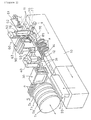
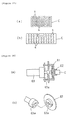
- FIG. 1 One example of apparatus for producing wire harnesses in which terminals with electric wires are mounted in a connector housing according to the present invention is illustrated in Figure 1.
- the apparatus has guide rails 11 equipped on a base stand 10.
- a mounting machine 20 for terminals t , a measuring machine 30 for electric wires a , a press-connecting machine 40, an inspection device 50 and a terminal-mounting machine 60 are arranged along the guide rails 11.
- a jig pallet 12 is moved from left to right by a conveyor as shown by the chain line arrow mark on the afore-mentioned guide rail 11.
- the jig pallet 12 descends downward by an elevator arm (not illustrated) when the pallet reaches the right end, is similarly moved to the left end by the conveyor, and is similarly positioned at the left end of the guide rail 11 by the elevator arm.
- the jig pallet 12 circulates the route (chain line arrow mark), and carries out the loading of the terminals t , the press-connecting of the wires a , and the delivery of the terminal.
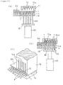
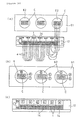
- the jig pallet 12 is a pallet in which six terminal-connecting jigs (blocks) 14 with cavities 14 a supporting the terminals t are arranged in parallel on a base 13 as shown in Figure 7.
- the numbers of the jigs 14 and the cavities 14 a are arbitrary, and they are generally determined by the number of connector housings mounting the press-connecting terminals t by one jig pallet 12 and the number of the cavities 14 a .
- this example is a case of producing the wire harnesses W wiring electric wires a as shown in Figure 21 and the like.
- the number of connector housings C is 3, and the cavities of the connector housings have upper and lower stages with 5 cavities in each stage.
- all of the jigs 14 can be constituted in a body.
- strip spring pieces 15 b of spring blades 15 are arranged in the respective cavities 14 under plate 16 to which the base parts 15 c of the respective spring blades 15 are fixed to the lower face with screws unifying the respective spring pieces 15 b .
- the terminals t When the terminals t are inserted in the cavities 14 a from the arrow mark direction, the terminals t are positioned by plates 16, and protrusions 15 a of the spring plates 15 are deflected as shown by the chain line and hook on the terminals t to prevent extraction of the terminals t .
- the terminals can also be mounted from above.
- the floating-up of terminals t is prevented by providing stiffening plates 17 on the plates 16.
- the stiffening plates 17 are installed on the base 13 and are designed to be removed during the transfer of terminals t described later (during pushing up).
- the plates 17 are usually lowered downward by the springs and oscillated upward resisting against the springs to allow upwards movement of terminals t .
- Two penetration holes 18 pass through the respective cavities 14 a from the lower face of the jigs 14.
- the terminal-mounting machine 20 mounts the terminals t in the respective cavities 14 a of the above-mentioned jigs 14 by selectively cutting the various terminals t one by one from the terminal belt of terminal reels T 1 - T 4 , as described in, for example, Japanese Patent Publication (unexamined) Hei No.10-208844.
- the mounting of the terminals t on the connector housing C is carried out by a unit of one jig 14, therefore the terminal t corresponding to the inserted terminal sequence is mounted on the respective jigs 14 in the sequence. Accordingly, there is a case of having empty cavities 14 a on the way.
- the terminal reels T 1 - T 4 properly move as the arrow mark, and correspond to the position accepting the terminal belt of the terminal-mounting machine 20.
- the electric wire-measuring machine 30 selects and sends the required electric wires a from a plurality of supplies S, measures the requisite length of a plurality of wires a at one time or one by one, and chucks the end of the wire with hand 31 to transfer the wire to the press-connecting machine 40 of the next stage, as disclosed in Japanese Patent Publication (unexamined) Hei No.10-154423, and Japanese Patent Applications Hei No.10-349947, No.10-337042 and the above-mentioned Japanese Patent Application Hei No.10-337249.
- the hand 31 goes back and forth in like manner as the arrow mark between the electric wire exit of the measuring machine 30 and the position of the press-connecting machine 40.
- the hand 31 may comprise one arm (refer to Japanese Patent Applications Hei No.10-337042 and No.10-337249).
- hands comprising two arms alternately delivering both hands to the measuring machine 30 and the press-connecting machine 40 to transfer the wires may be provided (refer to Japanese Patent Application Hei No.10-349947).
- the press connecting machine 40 press-connects the electric wires a one by one, or selectively press-connects a plurality of wires, transferred by the hand 31, in the requisite terminals t in the jig 14, as disclosed in Japanese Patent Publications (unexamined) Hei No.10-241473, No.10-106370, No.10-106371, and the above-mentioned respective applications which are not opened yet.
- the jig pallet 12 moves left and right, the terminal t at the requisite position is positioned at the press-connecting position, and the press-connecting is carried out.
- the press-connecting of various kinds of wiring arrangements can be carried out on the jig pallet 12, as disclosed in Japanese Patent Publication (unexamined) Hei No.10-241473.
- the jigs 14 are paired one after another in the direction of travel and the electric wires are only wired to the mutual pairs.
- FIG 19 various kinds of wiring arrangements such as an arrangement of arbitrarily wiring the electric wires between the respective jigs 14 can be carried out.
- the mode of wiring in Figure 19 becomes the wire harness W shown in Figure 21 in which the electric wires are crossed. Therefore, the electric wires are wired on the respective jigs 14 in accordance with the wiring arrangements of wire harness W.
- the jigs 14 are made of a hard metal such as steel or the like, the walls between the cavities 14 a are not bent by the pressing power of the press-connecting on the jigs 14. Accordingly, in case of jigs 14 made of a hard metal, there is no problem for inserting the terminals in the subsequent processes or the like, even if empty cavities without terminals are provided.
- the press-connecting on the jigs 14 is carried out by the same jigs 14 irrespective of the shapes of connector housings.
- the electric wire-measuring and press-connecting can be carried out by a robot uniting the electric wire-measuring machine 30 and the press-connecting machine 40 described in the fore-mentioned Japanese Patent Publication (unexamined) Hei No.10-106370.
- the inspection device 50 is a machine which picks up a condition of press-connecting the electric wires into the respective terminals t by a CCD camera and judges whether the press-connecting is proper or not based on the images. For example, the machine judges the normal press-connecting condition in comparison with an abnormal condition. The judgement may be carried out by a person or automatically.
- the terminal-mounting machine 60 is a machine in which the jig pallet 12 with terminals in which the electric wires a are press-connected moves as the arrow mark.
- the terminals t are taken out from the respective jigs 14, and the terminals t are mounted in the housings C on the connector housing retaining plates (pallet) 61 which move left and right.
- the details are shown in Figure 1 - Figure 6.
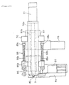
- an air cylinder 82 elevating a terminal-protruding jig 81 is arranged in the base stand 10 under the terminal-inserting position O.
- a hand 70 having a terminal inserting jig 71 is arranged above while keeping free elevation.
- the terminal-inserting jig 71 and the terminal-protruding jig 81 have the numbers of the terminals t which the I jig 14 can hold, the terminal-inserting jig 71 and pins 83 corresponding with the I jig 14 on the pallet 12.
- Terminal-inserting jig 71 has cavities 72 for the terminals t and grooves 72 a in which blades 73 (described later) are to be inserted extend upwards from the cavities 72 (refer to Figure 11). Further, a shutter 83 installed on the hand 70 is capable of passing under terminal inserting jig 71, and the pins 83 pass through holes 84 a of the shutter 84.
- the delivery is carried out at the cavities 14 a and 72 between the jigs 14 and 71. Therefore, the pick-up miss (delivery miss) decreases remarkably, and the terminal insertion miss of subsequent processes decreases remarkably. It is preferable to carry out the protrusion at two points p and q ( Figure 14) with two pins 83, but one pin may be sufficient, or three or more may be used. In either cases, the terminals t protrude the position to be transferred without being inclined.
- the hand 70 is supported under free elevation on upper frame 91 of slide cylinder 90 on the base stand 10 through supporting plate 78 and slider 79, and transfers back and forth at the waiting position and the mounting position by the movement of the frame 91 as the arrow mark by the slide cylinder 90.
- the elevation of the supporting plate 78 is carried out by the actuator equipped on the frame 91, and the supporting plate 78 elevates three positions such as the waiting position at the highest position, the inserting position at the lowest position and the mounting position at the middle position.
- the above-mentioned terminal-inserting jig 71 is arranged on the lower face of the edge of the hand 70, and the above-mentioned shutter 84 is arranged adjacent.
- a cylinder 85 advances and retreats the shutter 84 and, when delivery from the above-mentioned jig 14 to the inserting jig 71 finishes, the shutter 84 is sent to the lower face of the jig 71 by the cylinder 85 and falling off of the terminals t from the jig cavities 72 is prevented by providing the shutter 84 at the back and front of the lower face of the terminals t during the elevation of the hand 70.
- gaps required for delivering the shutter 84 between the jigs 14 and 71 may be formed during the above-mentioned descent of the hand 70 but, after the protrusion of the terminals by the pins 83, the gaps may be formed together with the pins 83, or by elevation by the gaps of grooves of the hand 70. For example, when the jigs 14 and 71 approach closer, or preferably contact with each other, the delivery becomes more sure.
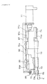
- the requisite number (five in the present mode of operation) of the insertion blades 73 are arranged in parallel on the insertion hand 70.
- Air cylinders 74 are respectively equipped on the respective blades 73.
- Selected insertion blades 73 are protruded by a requisite length (code r ) in comparison with other blades by selectively driving the air cylinders 74.
- Lock pins 75 are protruded with air cylinder 76 under the condition, and are passed through holes 73 a of the respective blades 73. After the hand 70 approaches nearby the connector housing C under the condition, all the blades 73 proceed by the air cylinder 77, and only the selected blades 73 push the terminals t and insert them in the cavities s of the connector housing C as shown in Figure 13 (b). In Figure 5 and Figure 6, 74 a are coil springs for returning the blades 73.
- the end parts 73 b of the selected blades 73 engage the end faces of the corresponding terminals t to which the electric wires a are connected.
- the terminals t are supported with the end parts 73 b and, therefore, nevertheless being pulled backward by the gravity of the electric wires a , the terminals t are transferred without being inclined.
- member 86 having the terminal-inserting jig 71 and member 87 with which the rod of the cylinder 77 is connected are arranged under free slide through the sliders 86 a and 87 a in back and forth directions along the rails 70 a of the hand base, and are connected with the expand shafts 88.
- One end of the shafts 88 a of the expand shafts 88 is supported by one side of a protrusion part of the member 86 under free advancing and retreating, and the other end is fixed by penetration through a protrusion part of the member 87.
- Coil springs 88 b are fitted on the shafts 88 a
- lock rings 88 c are fixed on the shafts 88 a to provide abutments for one end of the springs 88 b .
- both members 86 and 87 advance till one part of member 86 contacts with an adjustment screw 89, and after that, the other part of the member 87 proceeds against the biasing of the spring 88 b .
- the blades 73 advance against the inserting jig 71, and push out the terminals t and insert them into the connector housings C.
- guide protrusions 84 b may be formed on the shutter 84 and at the insertion of the terminals t, stabilisers t ' at both sides of the terminals t cross the guide protrusions 84 b .
- the shutter 84 may preferably guide the insertion of terminals t .
- the selecting action of the respective blades 73 when inserting the terminals t in the connector housing C is the same as the selecting action of the respective press-connecting blades described in Japanese Patent Publication (unexamined) Hei No.10-106371.
- the tact when a plural number of the terminals t are simultaneously mounted, the tact is remarkably shortened in comparison with a case of mounting the terminals one by one with the hand.
- the tact-up is limited by one by one, and in addition, the mounting miss caused by chucking miss is apt to occur.
- housings C having different sizes and housings C having lock parts can be corresponded, and when the intervals of the cavities s are an integer-fold, it can be corresponded.
- the above-mentioned connector housing retention plate 61 is supported under free slide to left and right directions by guides 69 arranged on the base stand 10.
- One end of the plate 61 is fixed on moving part 64 a of slide actuator 64 arranged on the base stand 10 and moves to left and right as shown in the chain line of Fig.3.
- the migration positions are 6 points in total including 3 points at which housing retention frames 62 described later correspond respectively with the terminal-mounting position 0, and 3 points from which they retreat at a requisite distance.
- the connector housing retention plate 61 is equipped with the housing retention frames 62 under free rotation.
- the housing retention frames 62 have protrusions 65 which support the housings C by pushing and springs 65 a which bias the protrusions 65.
- stop rings 66 of the protrusions 65 are pulled and the housing C is fitted on the retention frames 62, the housings C are pushed by the springs 65 a by removing the protrusions 65 (the stop rings 66) and surely fixed.
- the pressing power is regulated by the thrusting amount of the stop rings 66.
- the protrusions 65 are fitted in the regulators 66 a and provide the housing retention frames 62 at the mounting position, the cavities s of the I stage of the housing C become the terminal-inserting position.
- the upper frame of the base stand 10 at the rear of the connector housing-retaining plate 61 is equipped with rotary cylinder 63 at the insertion position 0.
- a drive part 63 a of the rotary cylinder 63 rotates while being fitted in a drive hole 62 a of the housing-retaining frames 62
- the connector housing C rotates by 180 degrees as from (a) to (b) of Fig.17, and is upset (rolled). This operation is carried out for the respective retention frame of the retention plate 61.
- the terminals t facing the connector housings C by the above-mentioned hand 70 are inserted in the cavities s of the housings C at the insertion position 0 from the back in accordance with the advancing of the blades 73 and mounted.
- the retention plate 61 moves by a requisite amount to left or right, the insertion hand 70 transfers to a motion of inserting the next terminals t with electric wires.
- the retreat of the afore-mentioned inserted housings C is carried out for preventing the entanglement of the electric wires a at receiving.
- the retention plate 61 moves so that the I housing C becomes the insertion position, then the I housing C is rolled and the insertion of the terminals t is carried out again.
- the insertion hand 70 is elevated in accordance with the migration of the retention plate 61, is positioned so that it does not interfere with the rolling action, and transfers to the inserting position by descending after the roll of the housings C.
- these actions insert the terminals t of the jigs 14 in the pallets 12 in sequence so that terminals t of jig a are inserted into the upper stage a of the I housing C, then the terminals t of jig b are inserted into the lower stage b of the I housing, and successively, the terminals t of jigs c , d , e and f of the pallet 12 are inserted into the II housing C and the III housing C.
- the order of insertion is properly changed considering the wiring specification, the degree of entanglement and the like.
- the retention plate 61 moves to the right end, the connector housings C are removed from the retention frames 62 by a person or a robot and new connector housings C are mounted on the retention frames 62.
- the jig pallet 12 is transferred to the terminal-mounting machine 20. The flow chart of the actions above is shown in Fig.20.
- the reason why the terminals t are inserted by rolling the connector housings C is to mount the terminals t arranged on the jig pallets 12 in parallel to the same direction so that the backs of the upper terminals and lower terminals face each other.
- the rolling is unnecessary.
- the insertion of the terminals t whose backs face each other has been carried out after rolling.
- the cavities are not limited to two stages, one stage may be used, and three stages or more may also be used. In the respective cases, the motion of the elevation of the insertion hand 70 and the like is corresponded with the number of stages.
- the wire harness W shown in Fig.21 can be obtained.
- This is the wire harness in which the terminals t are inserted from the back of the cavities s in like manner as the wire harness W by the press-clamping terminals. Accordingly, when a mode of operation capable of mounting the press-clamping terminals t in the connector housings C for the press-clamping terminals is set, the press-clamping terminals and the connector housings C can be used in common. Further, when there are the empty cavities s , not only the press-connecting terminals but also the press-clamping terminals can be also inserted (mounted) in the empty cavities s .
- terminal-connecting jigs 14 are shown in Fig.22 and Fig.23.
- the jigs 13 are provided with the protruding pins (pushing-up pins) 83.
- recesses 14 b are formed under the jig base 14', and pushing-up plates (protruding jigs) 81 with the above-mentioned pins 83 are fitted in the recesses 14 b under a condition of free elevation.
- the plates 81 are designed to be pushed up by the air cylinders 82, and the pins 83 are designed to be retreated from the cavities 14 a by the biasing of springs 86.
- the pushing-up plates 81 and the pins 83 are pushed up by the elevation of the piston rods 82' of the air cylinders 82 as shown in Fig.22(b), and the terminals t are pushed out (protruded) from the cavities 14 a by the pins 83 and delivered to the inserting jig 71.
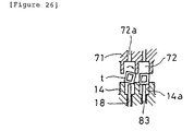
- FIG.24 and Fig.25 Another example of the inserting jig 71 is shown in Fig.24 and Fig.25, in which transfer mounting guides 72 b are provided on the lower face of the jig 71 on both sides of the cavities 72.
- FIG.26 in the absence of the guides 72 b , the presence of the shutter 84 creates gaps between the connector jig 14 and inserting jig 71. If a twisting force is generated in the electric wires when the terminals t are pushed up from connector jig 14 by the pins 83, the terminals t are subject to rolling by the twisting force as shown by the arrow mark and there is a risk this may cause a delivery miss.
- the terminals t are guided by the guides 72 b during the transfer from the connector jig 14 to the inserting jig 71. In this way, the terminals t are smoothly transferred from the cavities 14 a of the connector jig 14 to the cavities 72 of the inserting jig 71 without rolling.
- the width of the cavities 14 a of the connector jigs 14, the width of the cavities 72 of the inserting jig 71, and the width of the cavities s of the housings C are settled to be enlarged in this order, the terminals t having a narrowed crosswise width are inserted in the broader cavities in turn, and the inserting action becomes smooth.
- the present invention is the terminal-connecting jigs above, the press-connecting and the like are carried out in the jigs and the terminals can be mounted on the connector housings, the press-connecting terminals and the press-clamping terminals can be mounted on the I connector housing, and the common-usability of the housing and cost-down can be designed.
- the cost-down of electric wires with a connector, for example, a wire harness can be designed.
Landscapes
- Engineering & Computer Science (AREA)
- Manufacturing & Machinery (AREA)
- Manufacturing Of Electrical Connectors (AREA)
Description
- The present invention concerns improvements in or relating to mounting terminals with electric wires into connector housings. The invention has particular, but not exclusive application, for connecting terminals with electric wires and then inserting the terminals with electric wires into connector housings from the back.
- Press-connecting and press-clamping are mainly adopted for connecting electric wires with connector terminals in a wire harness and the like.
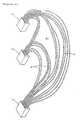
- A press-connecting connection (hereinafter, merely referred to as press-connecting) is shown in Figure 27. The press-connecting terminals t are loaded in the cavities s of a connector housing C. Press-connecting
blade guides 1 are matched with the connector housing C (Figure 27(a)), and electric wires a are supplied (Figure 27(b)), and pressed and connected in the terminals t by press-connecting blades 2 (Figure 27(c)). Namely, the press-connecting presses and loads the electric wires a into a connector housing C from above. - A press-clamping connection (hereinafter, merely referred to as press-clamping) successively press-clamps the connecting pieces of the terminals on the bare conductors after removing the covering of the electric wires. Accordingly, in general, the press-clamping press-clamps the terminals to every electric wire, chucks pick up the terminals one by one with a
hand 3 and insert them into the cavities s of the connector housing C from the back (terminal-inserting inlet) as shown in Figure 29 (refer to Japanese Patent Publication (unexamined) Hei No.9-115642 and the like). - In the above-mentioned press-connecting, for example, in the case of the connector housing C having the cavities s of two stages in a wire harness, the connector housing C is conventionally divided into an upper housing C1 and a lower housing C2 in order to press the electric-wires in from the upper face of each housing C1, C2 as shown in Figure 28. After the terminals t and the electric wires a are respectively loaded on the upper housing C1 and the lower housing C2 (from Figure 28(a) to Figure 28(b)), cover b is closed and both C1 and C2 are integrally connected together (Figure 28(c)) (refer to Japanese Patent Publication (unexamined) Hei No.10-335037 and the like).
- The conventional press-connecting requiring two housings C1 and C2 has further many working steps and it causes an increase in cost. Further, the walls e between the cavities may be bent outwards and the housings swollen by pressing power during press-connecting. As a result, it can happen that the cover b is not successfully closed and the upper housing C2 and the lower housing C1 are not successfully united. Further, from the viewpoint of reducing the bending problems of the cavity walls e, this type of connector C for press-connecting has terminals t in all of the cavities. However, it was found that mounting terminals t in the cavities s to which electric wires a are not press-connected did not avoid the problems. Further, dismantling of both housings C1 and C2 is required for newly press-connecting electric wires a in empty cavities s. As a result the press-connecting is virtually impossible.
- In the press clamping on the other hand, the terminals t with the electric wires a are mounted in the cavities s one by one from the back. As a result, only one connector housing C (not divided) is required in place of the two stage type connector C as described above. However it is necessary to connect the electric wires a on the terminals t one by one, and it has a problem in workability. In addition, the connection of the terminals t one by one is apt to cause a chucking miss. Further, since the electric wires a are inserted while being held, the electric wires a are apt to buckle as shown by the chain line of Figure 29, and such buckling causes a mounting miss.
- Further, in the case of the connector housing C having the cavities s of two stages or more, there is a connector housing which mounts the terminals t in the cavities s of the upper and lower stages so that their backs face each other. In this case, after the electric wires a are chucked with the
hand 3 as shown in Fig.30(a), the terminals t are inserted in the rotational jig D as shown in Fig.30(b), rolled in the direction of the arrow mark under a condition in which the chucking is released, and chucked again to be inserted in the cavities s as shown in Fig.30(c). The rolling action has occasionally the result of causing a twisting power on the electric wires a, and there is a risk that the terminals t cannot be straightforwardly re-chucked and a smooth insertion cannot be obtained. - US 5 630 273 (Kobayashi) discloses a holding jig for temporarily holding a plurality of last-in terminals with electric wires attached of a wire harness. The holding jig consists of a main body having a plurality of channels thereon for receiving the last-in terminals. The channels extend in a direct line from entry apertures for receiving the last-in terminals during loading of the holding jig, to exit apertures, for removing the last-in terminals from the holding jig. Resilient means temporarily retain the last-in terminals in the channels and prevent the last-in terminals from being removed from the holding jig via the entry apertures. To remove the last-in terminals from the holding jig contact members of an insertion jig are pushed through the channels to contact the last-in terminals contained therein pushing the terminals out of the holding jig via the exit apertures. The last-in terminals are loaded into the holding jig in the same direction as they are removed from the holding jig. The holding jig retains the last-in terminals for continuity testing of the connection before insertion of the last-in terminals into a connector housing.
- PT102 007A (Yazaki Corporation) discloses an apparatus and method of manufacturing a wiring harness subassembly having both crimp terminals and press-fit terminals. The apparatus comprises a cutting stage which cuts wires into desired lengths and a device for press-fitting or crimping terminals held in a connector retaining bar, onto the wires. The crimp terminals are removed and inserted into a connector housing.
- The present invention aims to provide a solution to the problems and disadvantages of the known press-connecting and press-clamping connections above-described.
- According to a first aspect of the present invention there is provided a process for mounting terminals with electric wires into a connector housing comprising the steps of, loading the terminals into a terminal-connecting jig, connecting the electric wires with the terminals, removing terminals with electric wires from the terminal-connecting jig, and inserting the terminals with electric wires from the back into cavities of the connector housing, characterised by the terminals with electric wires are removed out of the terminal-connecting jig in a direction transverse to a longitudinal direction of the terminals in the terminal-connecting jig by pins of a pushing-out jig pushed through holes below the terminals in the terminal connecting jig.
- By this invention, a process of connecting the electric wires on the terminals can be achieved which enables the terminals to be inserted and loaded with electric wires in the cavities of the connector housing from the back. As a result, a cost saving can be obtained.
- In order to do so, if press-connecting terminals are firstly loaded in the jigs, the electric wires can be loaded from the upper surface of the jig for press-connecting in like manner to the conventional process. In this way, the press connecting terminals with electric wires can be obtained by press-connecting without any trouble.
- Then, if the press-connecting terminals with electric wires are removed from the terminal-connecting jigs and loaded in the connector housing, the press-connecting terminals can be inserted in the cavities of the connector housing from the back in like manner to the press-clamping terminals of Figure 29, and workability is splendid.
- If press-clamping is carried out in place of press-connecting, for example, if press-clamping terminals are loaded in the jigs and the electric wires, after peeling, are press-clamped on the terminals, the press-clamping terminals can be inserted in the connector housing according to a similar action, and workability is again splendid.
- Preferably, each terminal with electric wire is removed by one pin of the pushing-out jig.
- Advantageously, each terminal with electric wire is removed by two pins which contact the terminal in the longitudinal direction before and behind the electric wire connecting area.
- Preferably, the steps of loading the terminals into the terminal connecting jig, connecting the electric wires with the terminals, removing the terminals with the wires from the terminal-connecting jig, and inserting the terminals with electric wires from the back into cavities of the connector housing are sequentially carried out automatically.
- In the case where the housing has two stages, an upper stage and a lower stage, the housing is preferably rolled (inverted) for inserting the terminals with electric wires from the back into cavities of the upper and lower stages.
- The terminals with electric wires may conveniently be loaded into cavities in the connecting jig and are preferably prevented from falling out by protrusions on spring plates below the cavities.
- Preferably, the terminals are loaded into the cavities from the front of the terminal-connecting jig and a plate at the rear of the terminal-connecting jig assists in positioning of the terminals in the cavities by abutment of the terminals.
- Advantageously, the terminals with electric wires are transferred to a terminal-inserting jig from the terminal-connecting jig, and the terminals with electric wires are inserted into the cavities of the connector housing from the terminal-inserting jig.
- Preferably, the terminals with electric wires are transferred from the terminal-connecting jig to cavities in the terminal-inserting jig and are preferably prevented from falling out of the cavities by a shutter. The terminals may conveniently be guided when pushed out of the inserting jig by guides on the shutter and a clearance is preferably provided in the shutter for the pins.
- Advantageously, the terminals with electric wires are guided when transferred to the inserting jig by transfer guides on both sides of the cavities.
- Preferably, the terminals with electric wires are transferred from the inserting jig to the cavities of the connector housing by members which push out the terminals in the longitudinal direction and support rear end faces of the terminals.
- The members may have holes therethrough and lock pins may be passed through the members to lock the members into a position so as each member protrudes by a requisite length and only selected members push the terminals into the cavities of the connector housing.
- In a preferred embodiment of the present invention, a method of mounting terminals with electric wires into connector housings comprises the steps of:-
- (a) providing a connector jig having one or more cavities for receiving a terminal;
- (b) inserting at least one terminal in a cavity of the connector jig;
- (c) connecting a wire to said at least one terminal located in said cavity;
- (d) providing an inserting jig having one or more cavities for receiving a terminal with a wire connected thereto;
- (e) relatively moving said connector jig and said inserting jig to position said connector jig below said inserting jig to align said cavity with the terminal and electric wire connected thereto in said connector jig with a cavity in said inserting jig;
- (f) transferring said at least one terminal with said wire connected thereto from said connector jig to said inserting jig by applying a force to an underside of said terminal to displace said terminal with said wire connected thereto upwards into said cavity in said inserting jig;
- (g) providing a connector housing having one or more cavities for receiving a terminal with a wire connected thereto;
- (h) relatively moving said inserting jig and said connector housing to align said cavity with the terminal and wire connected thereto in said inserting jig with a cavity in said connector housing; and
- (i) transferring said at least one terminal with said wire connected thereto from said cavity in said inserting jig to said connector housing.
-
- According to a second aspect of the present invention there is provided a system for mounting terminals with electric wires in a connector housing comprising electric wire-measuring and wire-connecting machines for connecting wires to the terminals, characterised in that the system further comprises a mounting machine for mounting the terminals on a terminal-connecting jig, and a terminal-mounting machine for removing the terminals with electric wires from the terminal connecting jig and inserting the terminals with electric wires from the back into cavities of the connector housing, wherein pins of a pushing out jig are arranged to be pushed through holes in the terminal connecting jig below the terminals whereby the terminals with electric wires are removed out of the terminal-connecting jig in a direction transverse to a longitudinal direction of the terminals in the terminal-connecting jig.
- Preferably, two pins are arranged to be pushed upwardly through the holes to remove each terminal with the electric wire from the terminal-connecting jig.
- Preferably, the machines are sequentially installed along guide rails.
- Advantageously, an inserting jig is provided to receive the terminals with electric wires from the connecting jig and insert the terminals with electric wires into the cavities in the connector housing.
- Preferably, a mechanism is provided for inserting the terminals with electric wires into the cavities of the connector housing by pushing the terminals out from the terminal-inserting jig.
- In one arrangement, the mechanism has a plurality of blades movable in an inserting direction for inserting respective terminals with electric wires into the cavities of the connector housing. The blades may be independently movable. Alternatively, a selection mechanism may be provided for moving selected blades as a unit.
- Advantageously, a roll over mechanism is provided for supporting the connector housing in either one of two positions to present selected cavities for inserting the terminals with electric wires. For example, the connector housing preferably has upper and lower stages and the roll over mechanism includes a frame for mounting the connector housing and means for rotating the frame through 180° to roll over (invert) the connector housing whereby the connector housing is supported in a first position to present the cavities of the upper stage for inserting the terminals and is rolled over and supported in a second position to present the cavities of the lower stage for inserting the terminal.
- Preferably, the connecting jig has cavities for mounting the terminals arranged in parallel on an upper face and the pushing-up pins contact a lower face of the terminals and strip off the terminals so that the terminals on which the electric wires are connected are capable of being stripped off upwards from the cavities.
- Advantageously, the terminals are loaded from the front of the cavities in the connecting jig, contacted with the back of the cavities, and hooked on protrusions of spring plates arranged under the cavities to prevent the terminals falling out. In this way, the terminals are stabilised in the cavities and the action of attaching the wires such as the press-connecting or the like is stabilised.
- More particularly, after the terminals are loaded in the respective cavities of the connecting jig, the electric wires are press-connected or press-clamped on the respective terminals from above, the pushing-up pins are raised through the penetration holes from below, and the terminals with electric wires attached are ejected from the cavities. Accordingly, the terminals are received and mounted in the connector housing. At this time, if the receiving of the terminals can be unified, a unified mounting can be carried out.
- When the above-mentioned terminals are press-connecting terminals, the electric wires can be loaded from the top of the connecting jigs in like manner as a conventional process. The press-connecting terminals with electric wires can be obtained by press-connecting without any trouble if the press connecting terminals are loaded in the connecting jigs and the electric wires are press connected on the press-connecting terminals. In this case, it is designed to remove the terminals with electric wires from the connecting jigs and load them in the connector housings. Thus, the press-connecting terminals can be inserted in the cavities of the connector housings from the back in like manner as the press-clamping terminals of Figure 29, and workability is splendid. The press clamping can be also carried out on the retaining jigs.
- In one arrangement, the connecting jigs can be provided with pushing-up pins under a condition capable of protrusion through the respective penetration holes in a lower face of the cavities. For example, the pushing-up pins may be provided on a pushing-up plate freely movable on the base of the connecting jig with the pushing-up plate pushed up and elevated from the underside of the base by actuator means. Thus, when the arrangement of cavities in the connector housing is changed and the connector jigs only need to be changed to correspond to the change. Namely, the actuator means to carry out the pushing-up action can be used in common with the connecting jigs of different modes (refer to the mode of operation in Figure 22 and Figure 23).
- Preferably, springs are arranged on the base of the connecting jigs for moving the pushing-up plate in the return direction in which the pushing-up pins retreat from the cavities. As a result, the return action such as by self-weight of the pushing-up plates or the like, or the return action by the actuator means or the like becomes unnecessary. In this way, the return action becomes sure and the cost can be reduced.
- Advantageously, two penetration holes are arranged in correspondence with the longitudinal direction of the terminals received in the cavities of the connector jig, and the pushing-up pins are arranged in correspondence with the penetration holes. As a result, the pushing-up pins are pushed up in the longitudinal direction of the terminals before and after the electric-wire connecting part of the terminals. In this way, the pushing-up action becomes stable because the pushing-up pins provide two contact points.
- More particularly, the two contact points support the load caused by the self-weight of electric-wires and, because the two points are before and after the connecting parts, the load caused by the self-weight of electric wires is steadily supported. Accordingly, the pushing-up action becomes more stable.
- In a preferred embodiment of the present invention there is provided apparatus for mounting terminals with connector wires into connector housings comprising:-
- (a) a connector jig having an upper surface;
- (b) at least one cavity in said upper surface for receiving a terminal;
- (c) at least one hole penetrating said cavity from below;
- (d) pin means for insertion in said at least one hole for displacing said terminal in an upwards direction;
- (e) means for connecting a wire to said terminal in said connector jig cavity;
- (f) an inserting jig having a lower surface;
- (g) at least one cavity in said lower surface for receiving a terminal;
- (h) means for aligning said at least one cavity in said upper surface of said connector jig with said at least one cavity in said lower surface of said inserting jig whereby said terminal with said wire connected thereto can be transferred from said connector jig to said inserting jig by actuation of said pin means;
- (i) a connector housing having a rear surface;
- (j) at least one cavity in said rear surface for receiving a terminal;
- (k) means for aligning said at least one cavity in said lower surface of said inserting jig with said at least one cavity in said connector housing; and
- (l) means for transferring said terminal with said wire connected thereto from said inserting jig to said connector housing.
-
- Preferably, the connector jig has a plurality of cavities in the upper surface, the inserting jig has a plurality of cavities in the lower surface, and the connector housing has a plurality of cavities in the rear surface whereby one or more terminals with wires attached thereto can be transferred from the connector jig to the connector housing via the inserting jig.
- Advantageously, a plurality of connector housings are provided and the inserting jig is operable to transfer terminals with wires connected thereto from the connector jig to the connector housings in a pre-determined manner.
- Other features, benefits and advantages of the invention will be apparent from the following description, given by way of example only, of embodiments of the invention in each of its aspects with reference to the accompanying drawings wherein:-
- Figure 1 is a schematic perspective view of apparatus embodying the invention;
- Figure 2 is a left side view partially in cross-section of the terminal-mounting part of the apparatus shown in Figure 1;
- Figure 3 is a partial front view of the terminal-mounting part shown in Figure 2;
- Figure 4 is a plan view of the hand part of the terminal-mounting part shown in Figures 2 and 3;
- Figure 5 is a front view partially in cross-section, of the hand part shown in Figures 2 and 4;
- Figure 6 is a bottom view of the hand part shown in Figures 2 to 5;
- Figure 7 is a plan view of a jig pallet;
- Figures 8(a)(b) are perspective and cross-sectional views of the terminal connecting jig;
- Figure 9 is a detailed perspective view of part of terminal mounting part shown in Figure 3;
- Figure 10 is a schematic view of the terminal-mounting action of the apparatus;
- Figure 11 is an exploded perspective view of the delivery action from the terminal-connecting jig to the inserting jig;
- Figures 12 (a)(b)(c) show the delivery action from the terminal-connecting jig to the inserting jig;
- Figures 13 (a)(b) show the terminal-inserting action;
- Figure 14 shows a further detail of the terminal-inserting action;
- Figures 15 (a)(b) show a comparison of the terminal-inserting action of the present invention and the prior art;
- Figures 16 (a)(b) are a schematic cross-section and exploded perspective view of the retention-rolling part of the connector housing;
- Figures 17 (a)(b) show schematically the terminal-mounting action to the connector housing;
- Figures 18 (a)(b)(c) show the terminal-mounting in more detail;
- Figure 19 shows an alternative terminal-mounting;
- Figure 20 is a flow chart of the operation of the apparatus;
- Figure 21 is an example drawing of a wire harness manufactured by the apparatus;
- Figures 22 (a)(b) show an alternative connecting jig before and after transfer of the terminals to the inserting jig;
- Figures 23 (a)(b) show another detail of the connecting jig shown in Figures 22 (a)(b);
- Figures 24 (a)(b) show the delivery action from the connecting jig to an alternative inserting jig;
- Figures 25 (a)(b)(c) show details of the delivery action to the inserting jig of Figure 24;
- Figure 26 shows a further detail of the delivery action to the inserting jig;
- Figures 27 (a)(b)(c) show a press-connecting action according to the prior art;
- Figures 28 (a)(b)(c) show another press-connecting action according to the prior art;
- Figure 29 shows the mounting action of a press-clamping terminal according to the prior art; and
- Figures 30 (a)(b)(c) shows a further detail of the mounting action according to the prior art.
-
- One example of apparatus for producing wire harnesses in which terminals with electric wires are mounted in a connector housing according to the present invention is illustrated in Figure 1.
- The apparatus has
guide rails 11 equipped on abase stand 10. A mountingmachine 20 for terminals t, a measuringmachine 30 for electric wires a, a press-connectingmachine 40, aninspection device 50 and a terminal-mountingmachine 60 are arranged along the guide rails 11. - As disclosed in, for example, Japanese Patent Publication (unexamined) Hei No.10-241473, and Japanese Patent Applications Hei No.10-337249 and No.10-350013, a
jig pallet 12 is moved from left to right by a conveyor as shown by the chain line arrow mark on the afore-mentionedguide rail 11. Thejig pallet 12 descends downward by an elevator arm (not illustrated) when the pallet reaches the right end, is similarly moved to the left end by the conveyor, and is similarly positioned at the left end of theguide rail 11 by the elevator arm. Namely, thejig pallet 12 circulates the route (chain line arrow mark), and carries out the loading of the terminals t, the press-connecting of the wires a, and the delivery of the terminal. - The
jig pallet 12 is a pallet in which six terminal-connecting jigs (blocks) 14 withcavities 14a supporting the terminals t are arranged in parallel on a base 13 as shown in Figure 7. The numbers of thejigs 14 and thecavities 14a are arbitrary, and they are generally determined by the number of connector housings mounting the press-connecting terminals t by onejig pallet 12 and the number of thecavities 14a. For example, this example is a case of producing the wire harnesses W wiring electric wires a as shown in Figure 21 and the like. The number of connector housings C is 3, and the cavities of the connector housings have upper and lower stages with 5 cavities in each stage. Therefore, as described later, the group number of the press-connecting terminals mounted from the onejig pallet 12 is 3 x 2 = 6, and since the number of terminals in the group is 5, thejigs 14 are 6, and thecavities 14a are 5. For example, all of thejigs 14 can be constituted in a body. - In the
jigs 14, as shown in Figure 8,strip spring pieces 15b ofspring blades 15 are arranged in therespective cavities 14 underplate 16 to which thebase parts 15c of therespective spring blades 15 are fixed to the lower face with screws unifying therespective spring pieces 15b. - When the terminals t are inserted in the
cavities 14a from the arrow mark direction, the terminals t are positioned byplates 16, andprotrusions 15a of thespring plates 15 are deflected as shown by the chain line and hook on the terminals t to prevent extraction of the terminals t. The terminals can also be mounted from above. - The floating-up of terminals t is prevented by providing
stiffening plates 17 on theplates 16. Thestiffening plates 17 are installed on thebase 13 and are designed to be removed during the transfer of terminals t described later (during pushing up). Theplates 17 are usually lowered downward by the springs and oscillated upward resisting against the springs to allow upwards movement of terminals t. Two penetration holes 18 pass through therespective cavities 14a from the lower face of thejigs 14. - The terminal-mounting
machine 20 mounts the terminals t in therespective cavities 14a of the above-mentionedjigs 14 by selectively cutting the various terminals t one by one from the terminal belt of terminal reels T1 - T4, as described in, for example, Japanese Patent Publication (unexamined) Hei No.10-208844. At this time, the mounting of the terminals t on the connector housing C is carried out by a unit of onejig 14, therefore the terminal t corresponding to the inserted terminal sequence is mounted on therespective jigs 14 in the sequence. Accordingly, there is a case of havingempty cavities 14a on the way. The terminal reels T1 - T4 properly move as the arrow mark, and correspond to the position accepting the terminal belt of the terminal-mountingmachine 20. - The electric wire-measuring
machine 30 selects and sends the required electric wires a from a plurality of supplies S, measures the requisite length of a plurality of wires a at one time or one by one, and chucks the end of the wire withhand 31 to transfer the wire to the press-connectingmachine 40 of the next stage, as disclosed in Japanese Patent Publication (unexamined) Hei No.10-154423, and Japanese Patent Applications Hei No.10-349947, No.10-337042 and the above-mentioned Japanese Patent Application Hei No.10-337249. - The
hand 31 goes back and forth in like manner as the arrow mark between the electric wire exit of the measuringmachine 30 and the position of the press-connectingmachine 40. Thehand 31 may comprise one arm (refer to Japanese Patent Applications Hei No.10-337042 and No.10-337249). Alternatively, hands comprising two arms alternately delivering both hands to the measuringmachine 30 and the press-connectingmachine 40 to transfer the wires may be provided (refer to Japanese Patent Application Hei No.10-349947). - The
press connecting machine 40 press-connects the electric wires a one by one, or selectively press-connects a plurality of wires, transferred by thehand 31, in the requisite terminals t in thejig 14, as disclosed in Japanese Patent Publications (unexamined) Hei No.10-241473, No.10-106370, No.10-106371, and the above-mentioned respective applications which are not opened yet. At this time, thejig pallet 12 moves left and right, the terminal t at the requisite position is positioned at the press-connecting position, and the press-connecting is carried out. - Accordingly, the press-connecting of various kinds of wiring arrangements can be carried out on the
jig pallet 12, as disclosed in Japanese Patent Publication (unexamined) Hei No.10-241473. For example, as shown in Figure 1 and Figure 18, thejigs 14 are paired one after another in the direction of travel and the electric wires are only wired to the mutual pairs. - Alternatively, as shown in Figure 19, various kinds of wiring arrangements such as an arrangement of arbitrarily wiring the electric wires between the
respective jigs 14 can be carried out. The mode of wiring in Figure 19 becomes the wire harness W shown in Figure 21 in which the electric wires are crossed. Therefore, the electric wires are wired on therespective jigs 14 in accordance with the wiring arrangements of wire harness W. - Further, when the
jigs 14 are made of a hard metal such as steel or the like, the walls between thecavities 14a are not bent by the pressing power of the press-connecting on thejigs 14. Accordingly, in case ofjigs 14 made of a hard metal, there is no problem for inserting the terminals in the subsequent processes or the like, even if empty cavities without terminals are provided. - Further, when the shapes of the cavities are the same, the press-connecting on the
jigs 14 is carried out by thesame jigs 14 irrespective of the shapes of connector housings. For example, the electric wire-measuring and press-connecting can be carried out by a robot uniting the electric wire-measuringmachine 30 and the press-connectingmachine 40 described in the fore-mentioned Japanese Patent Publication (unexamined) Hei No.10-106370. - The
inspection device 50 is a machine which picks up a condition of press-connecting the electric wires into the respective terminals t by a CCD camera and judges whether the press-connecting is proper or not based on the images. For example, the machine judges the normal press-connecting condition in comparison with an abnormal condition. The judgement may be carried out by a person or automatically. - As shown in Figure 10, the terminal-mounting
machine 60 is a machine in which thejig pallet 12 with terminals in which the electric wires a are press-connected moves as the arrow mark. When thepallet 12 comes to the terminal-insertingposition 0, the terminals t are taken out from therespective jigs 14, and the terminals t are mounted in the housings C on the connector housing retaining plates (pallet) 61 which move left and right. The details are shown in Figure 1 - Figure 6. - Namely, an
air cylinder 82 elevating a terminal-protrudingjig 81 is arranged in the base stand 10 under the terminal-inserting position O. Ahand 70 having aterminal inserting jig 71 is arranged above while keeping free elevation. The terminal-insertingjig 71 and the terminal-protrudingjig 81 have the numbers of the terminals t which theI jig 14 can hold, the terminal-insertingjig 71 and pins 83 corresponding with theI jig 14 on thepallet 12. Terminal-insertingjig 71 hascavities 72 for the terminals t andgrooves 72a in which blades 73 (described later) are to be inserted extend upwards from the cavities 72 (refer to Figure 11). Further, ashutter 83 installed on thehand 70 is capable of passing underterminal inserting jig 71, and thepins 83 pass through holes 84a of theshutter 84. - Accordingly, as shown in Figure 12(a), when the terminal-protruding
jig 81 is elevated against thejigs 14 at the inserting position, therespective pins 83 protrude through the penetration holes 18 of thejigs 14 and transfer the terminals t in thecavities 14a to the insertingjig 71 as shown in Figure 12(b) and Figure 12(c). At the protrusion, thepins 83 contact the press-connecting member of the terminals t back and forth in the longitudinal direction at two pints p and q (Figure 14) and protrude the terminals t. - Further, as shown in Figure 5 and Figure 13, selected blades 73 (described later) preliminary proceed against
other blades 73 and ends 73b contact end faces of the terminals t to which the electric wires a are connected. Therefore, nevertheless, being pulled backward by the gravity of the electric wires a, the terminals t are transferred (received) within thejigs 71 without being inclined. - The delivery is carried out at the
cavities jigs pins 83, but one pin may be sufficient, or three or more may be used. In either cases, the terminals t protrude the position to be transferred without being inclined. - As shown in Figure 2, the
hand 70 is supported under free elevation onupper frame 91 ofslide cylinder 90 on the base stand 10 through supportingplate 78 andslider 79, and transfers back and forth at the waiting position and the mounting position by the movement of theframe 91 as the arrow mark by theslide cylinder 90. The elevation of the supportingplate 78 is carried out by the actuator equipped on theframe 91, and the supportingplate 78 elevates three positions such as the waiting position at the highest position, the inserting position at the lowest position and the mounting position at the middle position. - The above-mentioned terminal-inserting
jig 71 is arranged on the lower face of the edge of thehand 70, and the above-mentionedshutter 84 is arranged adjacent. Acylinder 85 advances and retreats theshutter 84 and, when delivery from the above-mentionedjig 14 to the insertingjig 71 finishes, theshutter 84 is sent to the lower face of thejig 71 by thecylinder 85 and falling off of the terminals t from thejig cavities 72 is prevented by providing theshutter 84 at the back and front of the lower face of the terminals t during the elevation of thehand 70. - Further, gaps required for delivering the
shutter 84 between thejigs hand 70 but, after the protrusion of the terminals by thepins 83, the gaps may be formed together with thepins 83, or by elevation by the gaps of grooves of thehand 70. For example, when thejigs - As shown in Figure 6 and Figure 13, the requisite number (five in the present mode of operation) of the
insertion blades 73 are arranged in parallel on theinsertion hand 70.Air cylinders 74 are respectively equipped on therespective blades 73.Selected insertion blades 73 are protruded by a requisite length (code r) in comparison with other blades by selectively driving theair cylinders 74. - Lock pins 75 are protruded with
air cylinder 76 under the condition, and are passed throughholes 73a of therespective blades 73. After thehand 70 approaches nearby the connector housing C under the condition, all theblades 73 proceed by theair cylinder 77, and only the selectedblades 73 push the terminals t and insert them in the cavities s of the connector housing C as shown in Figure 13 (b). In Figure 5 and Figure 6, 74a are coil springs for returning theblades 73. - Further, as shown in Figure 5 and Figure 13, the
end parts 73b of the selectedblades 73 engage the end faces of the corresponding terminals t to which the electric wires a are connected. The terminals t are supported with theend parts 73b and, therefore, nevertheless being pulled backward by the gravity of the electric wires a, the terminals t are transferred without being inclined. - As shown in Figure 4 and Figure 5 at this time,
member 86 having the terminal-insertingjig 71 andmember 87 with which the rod of thecylinder 77 is connected are arranged under free slide through thesliders rails 70a of the hand base, and are connected with the expandshafts 88. - One end of the
shafts 88a of the expandshafts 88 is supported by one side of a protrusion part of themember 86 under free advancing and retreating, and the other end is fixed by penetration through a protrusion part of themember 87. Coil springs 88b are fitted on theshafts 88a, lock rings 88c are fixed on theshafts 88a to provide abutments for one end of thesprings 88b. - Accordingly, when the
rod 77a of thecylinder 77 advances, bothmembers member 86 contacts with anadjustment screw 89, and after that, the other part of themember 87 proceeds against the biasing of thespring 88b. Theblades 73 advance against the insertingjig 71, and push out the terminals t and insert them into the connector housings C. - Further, it may be better to guide the terminals I during the insertion. For this, as shown in the chain line of Figure 11, guide
protrusions 84b may be formed on theshutter 84 and at the insertion of the terminals t, stabilisers t' at both sides of the terminals t cross theguide protrusions 84b. Namely, theshutter 84 may preferably guide the insertion of terminals t. Thus, the terminals t are smoothly inserted without vibrating in a crosswise direction. - The selecting action of the
respective blades 73 when inserting the terminals t in the connector housing C is the same as the selecting action of the respective press-connecting blades described in Japanese Patent Publication (unexamined) Hei No.10-106371. - Thus, as shown in Fig.15, when the terminals t are inserted by pushing out the
blades 73, closer spacing of the terminals t becomes possible by the cavities s of the connector housing C (Fig.15(a)) having smaller pitch than the pitch (Fig.15(b)) of the cavities for inserting the press-clamping terminals t of Fig.26, because nohand 3 is required. - Further, as shown in Fig.26, when a plural number of the terminals t are simultaneously mounted, the tact is remarkably shortened in comparison with a case of mounting the terminals one by one with the hand. For example, the tact-up is limited by one by one, and in addition, the mounting miss caused by chucking miss is apt to occur.
- Further, when the intervals of the cavities s are the same according to the selecting mechanism of the
respective blades 73, housings C having different sizes and housings C having lock parts can be corresponded, and when the intervals of the cavities s are an integer-fold, it can be corresponded. - As shown in Fig.2 and Fig. 3, the above-mentioned connector
housing retention plate 61 is supported under free slide to left and right directions byguides 69 arranged on thebase stand 10. One end of theplate 61 is fixed on movingpart 64a ofslide actuator 64 arranged on thebase stand 10 and moves to left and right as shown in the chain line of Fig.3. The migration positions are 6 points in total including 3 points at which housing retention frames 62 described later correspond respectively with the terminal-mountingposition - As shown in Fig.3 and Fig.9, the connector
housing retention plate 61 is equipped with the housing retention frames 62 under free rotation. The housing retention frames 62 haveprotrusions 65 which support the housings C by pushing andsprings 65a which bias theprotrusions 65. After stop rings 66 of theprotrusions 65 are pulled and the housing C is fitted on the retention frames 62, the housings C are pushed by thesprings 65a by removing the protrusions 65 (the stop rings 66) and surely fixed. The pressing power is regulated by the thrusting amount of the stop rings 66. Theprotrusions 65 are fitted in theregulators 66a and provide the housing retention frames 62 at the mounting position, the cavities s of the I stage of the housing C become the terminal-inserting position. - As shown in Fig.2 and Fig.16, the upper frame of the base stand 10 at the rear of the connector housing-retaining
plate 61 is equipped withrotary cylinder 63 at theinsertion position 0. When adrive part 63a of therotary cylinder 63 rotates while being fitted in adrive hole 62a of the housing-retainingframes 62, the connector housing C rotates by 180 degrees as from (a) to (b) of Fig.17, and is upset (rolled). This operation is carried out for the respective retention frame of theretention plate 61. - At this time, concerning the rotation of the
rotary cylinder 63 as shown in Fig.9, when theprotrusions 65 are fitted in theregulators 66a, the cavities s of the I stage becomes the inserting position by the fitting as afore-mentioned, but when it is rolled, the rotation position is regulated by thecylinder 63 itself so that the cavities s of the other stage becomes the inserting position. - Accordingly, the terminals t facing the connector housings C by the above-mentioned
hand 70 are inserted in the cavities s of the housings C at theinsertion position 0 from the back in accordance with the advancing of theblades 73 and mounted. - When the terminals t are inserted in the I stage of the I housing C, the
retention plate 61 moves by a requisite amount to left or right, theinsertion hand 70 transfers to a motion of inserting the next terminals t with electric wires. The retreat of the afore-mentioned inserted housings C is carried out for preventing the entanglement of the electric wires a at receiving. - After completion of the inserting, the
retention plate 61 moves so that the I housing C becomes the insertion position, then the I housing C is rolled and the insertion of the terminals t is carried out again. At this time, theinsertion hand 70 is elevated in accordance with the migration of theretention plate 61, is positioned so that it does not interfere with the rolling action, and transfers to the inserting position by descending after the roll of the housings C. - As shown in Fig.18(a), (b) and (c), these actions insert the terminals t of the
jigs 14 in thepallets 12 in sequence so that terminals t of jig a are inserted into the upper stage a of the I housing C, then the terminals t of jig b are inserted into the lower stage b of the I housing, and successively, the terminals t of jigs c, d, e and f of thepallet 12 are inserted into the II housing C and the III housing C. The order of insertion is properly changed considering the wiring specification, the degree of entanglement and the like. - After completion of mounting the terminals t with electric wires into all of the connector housings C, the
retention plate 61 moves to the right end, the connector housings C are removed from the retention frames 62 by a person or a robot and new connector housings C are mounted on the retention frames 62. On the other hand, thejig pallet 12 is transferred to the terminal-mountingmachine 20. The flow chart of the actions above is shown in Fig.20. - Thus, the reason why the terminals t are inserted by rolling the connector housings C is to mount the terminals t arranged on the
jig pallets 12 in parallel to the same direction so that the backs of the upper terminals and lower terminals face each other. When the directions are the same, the rolling is unnecessary. For example, the insertion of the terminals t whose backs face each other has been carried out after rolling. Further, the cavities are not limited to two stages, one stage may be used, and three stages or more may also be used. In the respective cases, the motion of the elevation of theinsertion hand 70 and the like is corresponded with the number of stages. - For example, according to the above-mentioned terminal-mounting, the wire harness W shown in Fig.21 can be obtained. This is the wire harness in which the terminals t are inserted from the back of the cavities s in like manner as the wire harness W by the press-clamping terminals. Accordingly, when a mode of operation capable of mounting the press-clamping terminals t in the connector housings C for the press-clamping terminals is set, the press-clamping terminals and the connector housings C can be used in common. Further, when there are the empty cavities s, not only the press-connecting terminals but also the press-clamping terminals can be also inserted (mounted) in the empty cavities s.
- Other examples of the terminal-connecting
jigs 14 are shown in Fig.22 and Fig.23. In this arrangement thejigs 13 are provided with the protruding pins (pushing-up pins) 83. Namely, recesses 14b are formed under the jig base 14', and pushing-up plates (protruding jigs) 81 with the above-mentionedpins 83 are fitted in the recesses 14b under a condition of free elevation. Theplates 81 are designed to be pushed up by theair cylinders 82, and thepins 83 are designed to be retreated from thecavities 14a by the biasing ofsprings 86. - In this mode of operation, the pushing-up
plates 81 and thepins 83 are pushed up by the elevation of the piston rods 82' of theair cylinders 82 as shown in Fig.22(b), and the terminals t are pushed out (protruded) from thecavities 14a by thepins 83 and delivered to the insertingjig 71. - Even if the cavities s of the connector housings C are changed from Fig.23(a) to Fig.23(b) (even if the width of the cavities is changed from A to B (A < B)), by installing the
pins 83 on the terminal-connectingjigs 14 like this, only changing thejigs 14 is required to correspond with the connector housings C. - By contrast with the mode of operation of Fig.12 not only must the
jigs 14 be changed but also the pushing-up plates (protruding jigs) 81 with thepins 83 from theair cylinders 82 must be changed. This needs a tool-changing mechanism. It becomes a working in the base stand in hand-working, and troublesome. - Another example of the inserting
jig 71 is shown in Fig.24 and Fig.25, in whichtransfer mounting guides 72b are provided on the lower face of thejig 71 on both sides of thecavities 72. As shown in Fig.26, in the absence of theguides 72b, the presence of theshutter 84 creates gaps between theconnector jig 14 and insertingjig 71. If a twisting force is generated in the electric wires when the terminals t are pushed up fromconnector jig 14 by thepins 83, the terminals t are subject to rolling by the twisting force as shown by the arrow mark and there is a risk this may cause a delivery miss. However, as shown in Fig.24 and Fig.25, the terminals t are guided by theguides 72b during the transfer from theconnector jig 14 to the insertingjig 71. In this way, the terminals t are smoothly transferred from thecavities 14a of theconnector jig 14 to thecavities 72 of the insertingjig 71 without rolling. - Further, if the width of the
cavities 14a of the connector jigs 14, the width of thecavities 72 of the insertingjig 71, and the width of the cavities s of the housings C are settled to be enlarged in this order, the terminals t having a narrowed crosswise width are inserted in the broader cavities in turn, and the inserting action becomes smooth. - Further, if the press-clamping can be carried out in the terminal-connecting
jigs 14, a similar action effect as the above-mentioned press-connecting can be obtained in the press-clamping terminals. - As the present invention is the terminal-connecting jigs above, the press-connecting and the like are carried out in the jigs and the terminals can be mounted on the connector housings, the press-connecting terminals and the press-clamping terminals can be mounted on the I connector housing, and the common-usability of the housing and cost-down can be designed. The cost-down of electric wires with a connector, for example, a wire harness can be designed.
Claims (26)
- A process for mounting terminals (t) with electric wires (a) into a connector housing (C) comprising the steps of, loading the terminals (t) into a terminal-connecting jig (14), connecting the electric wires (a) with the terminals (t), removing terminals (t) with electric wires (a) from the terminal-connecting jig (14), and inserting the terminals (t) with electric wires (a) from the back into cavities (s) of the connector housing (C), characterised by the terminals (t) with electric wires (a) are removed out of the terminal-connecting jig (14) in a direction transverse to a longitudinal direction of the terminals (t) in the terminal-connecting jig (14) by pins (83) of a pushing-out jig (81) pushed through holes (18) below the terminals (t) in the terminal-connecting jig (14).
- A process as set forth in claim 1 characterised in that each terminal (t) with electric wire (a) is removed from the terminal-connecting jig (14) by one pin (83) of the pushing-out jig (81.
- A process as set forth in claim 1 characterised in that each terminal (t) with electric wire (a) is removed from the terminal-connecting jig (14) by two pins (83) of the pushing-out jig (81) which contact the terminal (t) in the longitudinal direction before and behind the electric wire connecting area.
- A process as set forth in any one of claims 1-3 characterised in that the steps of loading the terminals (t) into the terminal connecting jig (14), connecting the electric wires (a) with the terminals (t), removing the terminals (t) with the wires (a) from the terminal-connecting jig (14), and inserting the terminals (t) with electric wires (a) from the back into cavities (s) of the connector housing (C) are sequentially carried out automatically.
- A process as set forth in any one of the preceding claims characterised in that the housing (C) has two stages, an upper stage and a lower stage, and the housing (C) is rolled (inverted) for inserting the terminals (t) with electric wires (a) from the back into cavities (s) of the upper and lower stages.
- A process as set forth in any one of the preceding claims characterised in that the terminals (t) with electric wires (a) are loaded into cavities (14a) in the terminal-connecting jig (14) and are preferably prevented from falling out by protrusions (15a) on spring plates (15) below the cavities (14a).
- A process as set forth in claim 6 characterised in that the terminals (t) are loaded into the cavities (14a) from the front of the terminal-connecting jig (14) and a plate (16) at the rear of the terminal-connecting grid assists in positioning of the terminals (t) in the cavities (14a) by abutment of the terminals (t).
- A process as set forth in any one of the preceding claims characterised in that the terminals (t) with electric wires (a) are transferred to a terminal-inserting jig (71), and the terminals (t) with electric wires (a) are inserted into the cavities (s) of the connector housing (C) from the terminal-inserting jig (71).
- A process as set forth in claim 8 characterised in that the terminals (t) with electric wires (a) are transferred from the terminal-connecting jig (14) to cavities (72) in the terminal-inserting jig (71) and are preferably prevented from falling out of the cavities (72) by a shutter (84).
- A process as set forth in claim 9 characterised in that the terminals (t) are guided when pushed out of the terminal-inserting jig (71) by guides (84b) on the shutter (84).
- A process as set forth in claim 9 or claim 10 as dependent on claim 2 or claim 3 characterised in that a clearance (84a) is provided in the shutter (84) for the pins (83).
- A process as set forth in any one of claims 8 to 11 characterised in that the terminals (t) with electric wires (a) are guided when transferred to the terminal-inserting jig (71) by transfer guides (72b) on both sides of the cavities (72).
- A process as set forth in any one of claims 8 to 12 characterised in that the terminals (t) with electric wires (a) are transferred from the terminal-inserting jig (71) to the cavities (s) by members (73) which push out the terminals (t) in the longitudinal direction and support rear end faces of the terminals (t).
- A process as set forth in claim 13 characterised in that the members (73) have holes (73a) therethrough and lock pins (75) are passed through the members (73) to lock the members (73) into a position so as selected members (73) protrude by a requisite length and only the selected members (73) push the terminals (t) into the cavities (s) of the connector housing (C).
- A system for mounting terminals with electric wires in a connector housing comprising electric wire-measuring and wire-connecting machines (30;40) for connecting wires (a) to the terminals (t), characterised in that the system further comprises a terminal connecting jig (14), a pushing out jig (81), a mounting machine (20) for mounting the terminals (t) on the terminal-connecting jig (14), and a terminal-mounting machine (60) for removing the terminals (t) with electric wires (a) from the terminal-connecting jig (14) and inserting the terminals (t) with electric wires (a) from the back in cavities (s) of the connector housing (C), wherein the terminals (t) with electric wires (a) are removed out of the terminal-connecting jig (14) by pins (83) of the pushing-out jig (81) arranged to be pushed through holes (18) in the terminal-connecting jig (14) below the terminals (t) whereby the terminals (t) with electric wires (a) are removed out of the terminal-connecting jig (14) in a direction transverse to a longitudinal direction of the terminals (t) in the terminal-connecting jig (14).
- A system as set forth in claim 15 characterised in that two pins (83) are arranged to be pushed upwardly through holes (18) to remove each terminal (t) with the electric wire (a) from the terminal-connecting jig (14).
- A system as set forth in claim 15 or claim 16 characterised in that the pins (83) are provided on a pushing-out jig (81) separate from the terminal-connecting jig (14).
- A system as set forth in claim claim 15 or claim 16 characterised in that the pins (83) are provided on a pushing-up plate (81) forming part of the terminal-connecting jig (14).
- A system as set forth in any one of claims 15-18 characterised in that the machines (20;30;40;60) are sequentially installed along guide rails 11.
- A system as set forth in any one of claims 15-19 characterised in that a terminal-inserting jig (71) is provided to receive the terminals (t) with electric wires (a) from the terminal-connecting jig (14) and insert the terminals (t) with electric wires (a) into the cavities (s) in the connector housing (C).
- A system as set forth in claim 20 characterised in that a mechanism (70) is provided for inserting the terminals (t) with electric wires (a) into the cavities (s) of the connector housing (C) by pushing the terminals (t) out from the terminal-inserting jig (71).
- A system as set forth in claim 21 characterised in that the mechanism (70) has a plurality of blades (73) movable in an inserting direction for inserting respective terminals (t) with electric wires (a) into the cavities (s) of the connector housing (C).
- A system as set forth in claim 22 characterised in that the blades (73) are independently movable.
- A system as set forth in claim 22 characterised in that a selection mechanism is provided for moving selected blades (73) as a unit.
- A system as set forth in any one of claims 15 to 24 characterised in that a roll over mechanism is provided for supporting the connector housing (C) in either one of two positions to present selected cavities (s) for inserting the terminals (t) with electric wires (a).
- A system as set forth in claim 25 characterised in that the connector housing (C) has upper and lower stages and the roll over mechanism includes a frame (62) for mounting the connector housing (C) and means (63) for rotating the frame (62) through 180° to roll over (invert) the connector housing (C) whereby the connector housing (C) is supported in a first position to present the cavities (s) of the upper stage for inserting the terminals (t) and is rolled over and supported in a second position to present the cavities (s) of the lower stage for inserting the terminals (t).
Applications Claiming Priority (10)
| Application Number | Priority Date | Filing Date | Title |
|---|---|---|---|
| JP4876799 | 1999-02-25 | ||
| JP4876799 | 1999-02-25 | ||
| JP14346399A JP3248518B2 (en) | 1999-02-25 | 1999-05-24 | Method of mounting terminal with electric wire on connector housing and terminal transfer structure |
| JP14344899A JP3248517B2 (en) | 1999-02-25 | 1999-05-24 | Method and apparatus for mounting terminal with electric wire on connector housing |
| JP14321299 | 1999-05-24 | ||
| JP14309099A JP3303842B2 (en) | 1999-02-25 | 1999-05-24 | Holding jig for mounting terminals with electric wires in connector housing |
| JP14344899 | 1999-05-24 | ||
| JP14309099 | 1999-05-24 | ||
| JP14346399 | 1999-05-24 | ||
| JP14321299A JP3303843B2 (en) | 1999-02-25 | 1999-05-24 | Method and apparatus for mounting insulation displacement terminal with electric wire on connector housing |
Publications (2)
| Publication Number | Publication Date |
|---|---|
| EP1032094A1 EP1032094A1 (en) | 2000-08-30 |
| EP1032094B1 true EP1032094B1 (en) | 2003-05-28 |
Family
ID=27522739
Family Applications (1)
| Application Number | Title | Priority Date | Filing Date |
|---|---|---|---|
| EP20000301374 Expired - Lifetime EP1032094B1 (en) | 1999-02-25 | 2000-02-22 | Improvements in or relating to mounting terminals with electric wires into connector housings |
Country Status (2)
| Country | Link |
|---|---|
| EP (1) | EP1032094B1 (en) |
| DE (1) | DE60002927T2 (en) |
Cited By (1)
| Publication number | Priority date | Publication date | Assignee | Title |
|---|---|---|---|---|
| EP3155700B1 (en) | 2014-06-16 | 2018-07-11 | Delphi Technologies, Inc. | Method and device for assembling a connector housing |
Families Citing this family (2)
| Publication number | Priority date | Publication date | Assignee | Title |
|---|---|---|---|---|
| CN113783068B (en) * | 2021-08-06 | 2023-11-24 | 上海工程技术大学 | Automatic wire pressing method for electric connector assembly |
| CN114430130B (en) * | 2022-01-24 | 2023-06-06 | 广东工业大学 | Power failure maintenance device for power automation equipment |
Family Cites Families (3)
| Publication number | Priority date | Publication date | Assignee | Title |
|---|---|---|---|---|
| US4375229A (en) * | 1979-04-28 | 1983-03-01 | Yazaki Corporation | Method and apparatus of automatically positioning wire ends for multi-mode end processing |
| JP3413979B2 (en) * | 1994-08-24 | 2003-06-09 | 住友電装株式会社 | Temporary holding jig for post-insert terminal and insertion jig used for it |
| JP3632937B2 (en) * | 1996-05-20 | 2005-03-30 | 矢崎総業株式会社 | Harness manufacturing method, pressure welding machine, connector holding rod and pressure welding device |
-
2000
- 2000-02-22 EP EP20000301374 patent/EP1032094B1/en not_active Expired - Lifetime
- 2000-02-22 DE DE2000602927 patent/DE60002927T2/en not_active Expired - Fee Related
Cited By (1)
| Publication number | Priority date | Publication date | Assignee | Title |
|---|---|---|---|---|
| EP3155700B1 (en) | 2014-06-16 | 2018-07-11 | Delphi Technologies, Inc. | Method and device for assembling a connector housing |
Also Published As
| Publication number | Publication date |
|---|---|
| EP1032094A1 (en) | 2000-08-30 |
| DE60002927T2 (en) | 2004-05-19 |
| DE60002927D1 (en) | 2003-07-03 |
Similar Documents
| Publication | Publication Date | Title |
|---|---|---|
| US6990730B2 (en) | System for mounting terminals with electric wires in a connector housing | |
| US8528199B2 (en) | Manufacturing apparatus for wiring harnesses and a manufacturing method for wiring harnesses | |
| US5913553A (en) | Method of manufacturing a wiring harness | |
| EP0034433A2 (en) | An electrical connector, a method of gang terminating electrical conductors and apparatus for carrying out the method | |
| EP0576277B1 (en) | Automated wiring harness fabricating system | |
| EP0862251A1 (en) | Method of manufacturing wire harness for automobile use | |
| EP0330309A2 (en) | Crimped wire harness fabricator and method | |
| EP1032094B1 (en) | Improvements in or relating to mounting terminals with electric wires into connector housings | |
| US5063656A (en) | Apparatus for making a wire harness | |
| US5581873A (en) | Temporary holding member for a wiring assembly manufacturing apparatus | |
| US5575058A (en) | Connector housing supplying device | |
| EP0615318B1 (en) | Connector housing positioning unit | |
| JP3303843B2 (en) | Method and apparatus for mounting insulation displacement terminal with electric wire on connector housing | |
| EP0635915A2 (en) | Connector termination apparatus and method | |
| US4718167A (en) | Semi-automatic electrical harness fabricating apparatus and method | |
| US20020112985A1 (en) | Connector modules designed to be positioned on belts | |
| JP3248517B2 (en) | Method and apparatus for mounting terminal with electric wire on connector housing | |
| EP0280396A2 (en) | Semi-automatic electrical harness fabricating apparatus and method | |
| EP0833416A2 (en) | Method of manufacturing a wire harness | |
| JP3303842B2 (en) | Holding jig for mounting terminals with electric wires in connector housing | |
| JP3125014B2 (en) | Wire crimping harness manufacturing equipment | |
| JP2001110258A (en) | Manufacture of wireharness with insertion of terminal | |
| JP2001057117A (en) | Automatic pressure-connection device for manufacture of wire harness, and connector housing carrying jig pallet used for the same | |
| JP2888707B2 (en) | Terminal insertion guide device | |
| JP3428904B2 (en) | Harness manufacturing equipment |
Legal Events
| Date | Code | Title | Description |
|---|---|---|---|
| PUAI | Public reference made under article 153(3) epc to a published international application that has entered the european phase |
Free format text: ORIGINAL CODE: 0009012 |
|
| 17P | Request for examination filed |
Effective date: 20000310 |
|
| AK | Designated contracting states |
Kind code of ref document: A1 Designated state(s): DE FR GB |
|
| AX | Request for extension of the european patent |
Free format text: AL;LT;LV;MK;RO;SI |
|
| AKX | Designation fees paid |
Free format text: DE FR GB |
|
| 17Q | First examination report despatched |
Effective date: 20011016 |
|
| GRAH | Despatch of communication of intention to grant a patent |
Free format text: ORIGINAL CODE: EPIDOS IGRA |
|
| GRAH | Despatch of communication of intention to grant a patent |
Free format text: ORIGINAL CODE: EPIDOS IGRA |
|
| GRAA | (expected) grant |
Free format text: ORIGINAL CODE: 0009210 |
|
| AK | Designated contracting states |
Designated state(s): DE FR GB |
|
| REG | Reference to a national code |
Ref country code: GB Ref legal event code: FG4D |
|
| REF | Corresponds to: |
Ref document number: 60002927 Country of ref document: DE Date of ref document: 20030703 Kind code of ref document: P |
|
| ET | Fr: translation filed | ||
| PLBE | No opposition filed within time limit |
Free format text: ORIGINAL CODE: 0009261 |
|
| STAA | Information on the status of an ep patent application or granted ep patent |
Free format text: STATUS: NO OPPOSITION FILED WITHIN TIME LIMIT |
|
| 26N | No opposition filed |
Effective date: 20040302 |
|
| PGFP | Annual fee paid to national office [announced via postgrant information from national office to epo] |
Ref country code: DE Payment date: 20070215 Year of fee payment: 8 |
|
| PGFP | Annual fee paid to national office [announced via postgrant information from national office to epo] |
Ref country code: GB Payment date: 20070221 Year of fee payment: 8 |
|
| PGFP | Annual fee paid to national office [announced via postgrant information from national office to epo] |
Ref country code: FR Payment date: 20070208 Year of fee payment: 8 |
|
| GBPC | Gb: european patent ceased through non-payment of renewal fee |
Effective date: 20080222 |
|
| REG | Reference to a national code |
Ref country code: FR Ref legal event code: ST Effective date: 20081031 |
|
| PG25 | Lapsed in a contracting state [announced via postgrant information from national office to epo] |
Ref country code: DE Free format text: LAPSE BECAUSE OF NON-PAYMENT OF DUE FEES Effective date: 20080902 |
|
| PG25 | Lapsed in a contracting state [announced via postgrant information from national office to epo] |
Ref country code: FR Free format text: LAPSE BECAUSE OF NON-PAYMENT OF DUE FEES Effective date: 20080229 |
|
| PG25 | Lapsed in a contracting state [announced via postgrant information from national office to epo] |
Ref country code: GB Free format text: LAPSE BECAUSE OF NON-PAYMENT OF DUE FEES Effective date: 20080222 |