EP1032008A2 - Portable terminal - Google Patents
Portable terminal Download PDFInfo
- Publication number
- EP1032008A2 EP1032008A2 EP00101511A EP00101511A EP1032008A2 EP 1032008 A2 EP1032008 A2 EP 1032008A2 EP 00101511 A EP00101511 A EP 00101511A EP 00101511 A EP00101511 A EP 00101511A EP 1032008 A2 EP1032008 A2 EP 1032008A2
- Authority
- EP
- European Patent Office
- Prior art keywords
- input operation
- direction input
- operation switch
- switch knob
- curved portion
- Prior art date
- Legal status (The legal status is an assumption and is not a legal conclusion. Google has not performed a legal analysis and makes no representation as to the accuracy of the status listed.)
- Withdrawn
Links
Images



Classifications
-
- H—ELECTRICITY
- H04—ELECTRIC COMMUNICATION TECHNIQUE
- H04M—TELEPHONIC COMMUNICATION
- H04M1/00—Substation equipment, e.g. for use by subscribers
- H04M1/02—Constructional features of telephone sets
- H04M1/0202—Portable telephone sets, e.g. cordless phones, mobile phones or bar type handsets
-
- H—ELECTRICITY
- H01—ELECTRIC ELEMENTS
- H01H—ELECTRIC SWITCHES; RELAYS; SELECTORS; EMERGENCY PROTECTIVE DEVICES
- H01H13/00—Switches having rectilinearly-movable operating part or parts adapted for pushing or pulling in one direction only, e.g. push-button switch
- H01H13/70—Switches having rectilinearly-movable operating part or parts adapted for pushing or pulling in one direction only, e.g. push-button switch having a plurality of operating members associated with different sets of contacts, e.g. keyboard
-
- H—ELECTRICITY
- H01—ELECTRIC ELEMENTS
- H01H—ELECTRIC SWITCHES; RELAYS; SELECTORS; EMERGENCY PROTECTIVE DEVICES
- H01H2221/00—Actuators
- H01H2221/008—Actuators other then push button
- H01H2221/012—Joy stick type
-
- H—ELECTRICITY
- H01—ELECTRIC ELEMENTS
- H01H—ELECTRIC SWITCHES; RELAYS; SELECTORS; EMERGENCY PROTECTIVE DEVICES
- H01H2239/00—Miscellaneous
- H01H2239/03—Avoiding erroneous switching
Definitions
- the present invention relates to a portable terminal, such as a portable phone, in particular, it relates to a portable terminal characterized in a multi-direction switch knob structure.
- Portable terminals in particular, portable phones have been made smaller, lighter and thinner in response to demand from the users.
- multi-functions and a smaller size have been provided in accordance with the smaller size, lighter weight and thinner shape.
- a so-called joy stick switch which operates a plurality of switches with one input operation member, has been provided.
- a control stick-like shape is adopted in an in stalled appliance, but in general, a sphere-like shape is adopted in a portable appliance for realizing a smaller size.
- a remote controller to be used as an image switching operation switch of a television set (JP-A-6-251663) has been proposed.
- the remote controller comprises a joy stick knob 30 as the input operation member of the joy stick switch with a spherical or conical shape so as to be used as a multi-direction input operation switch knob.
- a cross direction input operation switch knob has a spherical or conical knob tip shape for facilitating operation in the cross directions.
- the multi-direction input operation switch knob projects drastically from the front surface of a portable terminal housing, occupying a large area. Besides, the projection may result in wrong operation during carriage.
- an object of the invention is to provide a portable terminal comprising a multi-direction input operation switch knob capable of operation easily and certainly without the need of enlarging the space of the key input operation portion even though the portable terminal is made smaller, and furthermore, capable of preventing wrong operation.
- the present invention is a portable terminal comprising a housing having a concave curved portion on a front surface thereof, and a multi-direction input operation member projecting from the bottom of the concave curved portion.
- a height of multi-direction input operation is less than a depth of concave curved portion, so a top of the multi-direction input operation member is provided without contacting with a flat surface of a rigid body when the housing is downwardly placed on the flat surface.
- a first aspect of the invention is a portable terminal comprising a housing having a concave curved portion on a front surface thereof, and a multi-direction input operation member projecting from the bottom of the concave curved portion, wherein a height of multi-direction input operation is less than a depth of concave curved portion, that is, a top of the multi-direction input operation member is placed under a plane including ends of concave curved portion, so a top of the multi-direction input operation member is provided without contacting with a flat surface of rigid body when the housing is downwardly placed on the flat surface, the effect of preventing wrong operation by providing the multi-direction input operation member without contacting with the flat surface of a rigid body even if the housing is placed on the flat surface with the concave curved portion downward can be achieved.
- a second aspect of the invention comprises the first aspect, wherein one of a concave portion and a convex portion is provided at an upper end of a pulling surface of the multi-direction input operation member, the effect of preventing wrong operation by providing the multi-direction input operation member without contacting with a flat surface of a rigid body even if the housing is downwardly placed on the flat surface as well as the effect of facilitating the operation of the multi-direction input operation member to the pulling side can be achieved.
- a third aspect of the invention comprises the first or second aspect, wherein a curved surface is formed on both side rims of the upper surface of the multi-direction input operation member, with the width of the upper surface set at a predetermined value, the effect of preventing wrong operation by providing the multi-direction input operation member without contacting with a flat surface of a rigid body even if the housing is placed the a flat surface with the concave curved portion downward as well as the effect of facilitating the operation of the multi-direction input operation member to the sliding direction can be achieved.
- a fourth aspect of the invention is any one of the first to third aspects, wherein the multi-direction input operation member is formed like a pyramid having a polygon with n vertices as its base so as to provide a multi-direction input operation switch having n contacts, the effect of preventing wrong operation by providing the multi-direction input operation member without contacting with a flat surface of a rigid body even if the housing is placed on the flat surface with the concave curved portion downward as well as the effect of realizing a multi-direction input operation switch having n contacts can be achieved.
- a concave curved portion is provided in a housing of a portable phone as well as a substantially quadrangular pyramid cross direction input operation switch knob is provided projecting from the concave curved portion so as to avoid contact of the cross direction input switch knob with the flat surface of the desk when the portable phone is placed on a desk with the concave curved portion downward.
- FIG. 1 is an external appearance view of a portable phone according to the first embodiment of the invention.
- the portable phone 1 has a case 2 and a cover 3, which comprise a housing, with an external antenna 9 mounted on the left upper end of the housing.
- On the surface of the cover 3 are provided a receiver portion 8, a display portion 6, a cross direction input operation switch knob 4, a ten key pad 5, and a transmitter portion 7 from above.
- the surface of the cover 3 is formed in a bow-like shape from the lower end portion of the display portion 6 to the receiver portion 7.
- the housing of the portable phone 1 has a narrow entire shape in consideration of convenience, with the cross direction input operation switch knob 4 mounted projecting on the bottom of the curved portion 10 formed on the surface of the cover 3. According to the projecting, the portable phone 1 can be grasped with one hand so as to facilitate operation.
- the cross direction input operation switch knob 4 is formed in a shape with an upper end portion of a quadrangular pyramid cut horizontally so as to have a small flat surface thereat.
- the arrows described in the upper and lower, and the right and left directions of the cross direction input operation switch knob 4 show the operation directions of the knob 4. That is, the arrows in the right and left directions show the sliding directions, the arrow in the upward direction shows the pushing direction, and the arrow in the downward direction shows the pulling direction.
- the degree of curvature of the curved portion 10 and the position and the degree of projection of the cross direction input operation switch knob 4 are set such that the cross direction input operation switch knob 4 does not come in contact with the flat surface of the desk 11 when it is placed on a desk 11 with the surface of the cover 3 downward. Therefore, according to the portable phone 1, even if the user places it on the desk 11 inadvertently with the surface of the cover 3 downward, the risk of wrong operation of a cross direction input operation switch 12 mounted on a printed board 14 in the housing can be avoided.
- the cross direction input operation switch knob 4 is mounted projecting from the bottom of the curved portion 10 on the surface of the cover 3, the portable phone 1 can be grasped with one hand so as to be operated easily. Moreover, even if it is placed on a desk inadvertently with the surface of the cover 3 downward, there is no risk of wrong operation of the cross direction input operation switch 12.
- the operation is further facilitated by skillfully providing the shape and the width of the cross direction input operation switch knob.
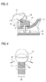
- FIGS. 3 and 4 are cross-sectional views showing the structure of a cross direction input operation switch knob 4 according to the second embodiment of the invention.
- FIGS. 3 and 4 portions corresponding to those of FIGS. 1 and 2 are applied with the same numerals used in the figures (the same is applied to the following embodiments).
- the entire structure of a portable phone provided with the cross direction input operation switch knob 4 is the same as that of FIG. 1 (the same is applied to the following embodiments).
- the cross direction input operation switch knob 4 projects from the bottom of the curved portion on the surface of the cover 3, the portable phone 1 can be grasped with one hand so as to be operated easily. Therefore, the user operates the cross direction input operation switch knob 4 with a finger 13 placed on the cross direction input operation switch knob 4.
- a pushing surface 15 substantially perpendicular to the surface of the cover 3 is provided so as to facilitate tilt of the cross direction input operation switch knob 4 to the pushing side in conducting the pushing operation 16 with the substantially lower half of the bulb of a finger 13.
- a pulling surface 17 is formed by providing a inclined surface with the front side of the cross direction input operation switch knob 4 (left side in FIG. 3) made higher so as to facilitate tilt of the cross direction input operation switch knob 4 to the pulling side in the downward action of the finger 13, that is, in conducting the pulling operation 18 with the substantially upper half of the bulb of a finger 13.
- a pair of sliding surfaces 19 with a small angle or a small curvature of the corner are provided on both side rims of the surface of the cross direction input operation switch knob 4 as well as the knob width 20 is set in the degree within the width of the finger 13 and the fresh of the bulb of the finger 13 is sufficient so that the cross direction input operation switch knob 4 can be caught by the bulb of the finger 13 easily in the action of moving the finger 13 in the right and left directions, that is, in conducting the sliding operation 21.
- the cross direction input operation switch knob 4 can be caught by the finger 13 easily with respect to the operation with movement in the sliding directions and the pulling direction so that the cross direction input operation switch knob 4 can be tilted easily for facilitating the input operation.
- the operation in the pulling direction is facilitated by providing a convex portion in the pulling surface so as to be caught easily by a finger.
- FIG. 5 is a cross-sectional view of a cross direction input operation switch knob 4 according to the third embodiment of the invention.
- a convex portion 22 is provided at the upper end of the pulling surface 17 of the cross direction input operation switch knob 4 (the upper end herein denotes the external antenna side of the housing of the portable phone 1, which is the right end side in FIG. 5). Since the convex portion 22 is provided at the upper end of the pulling surface 17, the cross direction input operation switch knob 4 can easily be caught by the finger 13 with respect to the operation with movement in the pulling direction so that the pulling surface 17 can be pulled easily by the finger 13.
- the operation in the pulling direction is facilitated by providing a concave portion in the pulling surface so as to be caught easily by a finger.
- FIG. 6 is a cross-sectional view showing the structure of a cross direction input operation switch knob 4 according to the fourth embodiment of the invention.
- a concave portion 23 is provided at the upper end of the pulling surface 17 of the cross direction input operation switch knob 4 (the right end side in FIG. 6). Since the concave portion 23 is provided at the upper end of the pulling surface 17, the cross direction input operation switch knob 4 can easily be caught by the finger 13 with respect to the operation with movement in the pulling direction so that the pulling surface 17 can be pulled easily by the finger 13.
- a multi-direction input operation switch having n contacts (n is an integer of 5 or more) can be used in the invention.
- the shape of the multi-direction input operation switch knob can be formed like a pyramid having a polygon with n vertices as its base.
- a concave curved portion is formed on the front surface of a portable terminal as well as a multi-direction input operation member provided projecting from the bottom surface of the curved portion is formed without contacting with the rigid body flat surface when the housing is downwardly placed on the flat surface, the effect of realizing an operation member ensuring certain switching operation without the risk of wrong operation in a small space can be achieved.
Landscapes
- Engineering & Computer Science (AREA)
- Signal Processing (AREA)
- Switches With Compound Operations (AREA)
- Transmitters (AREA)
Abstract
Description
Claims (5)
- A portable terminal comprising:a housing having a concave curved portion on a front surface thereof ; anda multi-direction input operation member projecting from a bottom of the concave curved portion,
wherein a height of the multi-direction input operation member is less than a depth of the concave curved portion. - The portable terminal according to claim 1,
wherein a top of the multi-direction input operation member is placed under a plane including ends of concave curved portion. - The portable terminal according to claim 1, wherein one of a concave portion and a convex portion is provided at an upper end of a pulling surface of the multi-direction input operation member.
- The portable terminal according to claim 1, wherein a curved surface is formed on both side rims of an upper surface of the multi-direction input operation member, with the width of the upper surface set at a predetermined value.
- The portable terminal according to claim 1, wherein the multi-direction input operation member is formed like a pyramid having a polygon with n vertices as its base so as to provide a multi-direction input operation switch having n contacts.
Applications Claiming Priority (2)
| Application Number | Priority Date | Filing Date | Title |
|---|---|---|---|
| JP11050801A JP2000251583A (en) | 1999-02-26 | 1999-02-26 | Mobile terminal |
| JP5080199 | 1999-02-26 |
Publications (2)
| Publication Number | Publication Date |
|---|---|
| EP1032008A2 true EP1032008A2 (en) | 2000-08-30 |
| EP1032008A3 EP1032008A3 (en) | 2001-11-28 |
Family
ID=12868890
Family Applications (1)
| Application Number | Title | Priority Date | Filing Date |
|---|---|---|---|
| EP00101511A Withdrawn EP1032008A3 (en) | 1999-02-26 | 2000-01-26 | Portable terminal |
Country Status (4)
| Country | Link |
|---|---|
| EP (1) | EP1032008A3 (en) |
| JP (1) | JP2000251583A (en) |
| CN (1) | CN1233002C (en) |
| NO (1) | NO20000765L (en) |
Family Cites Families (6)
| Publication number | Priority date | Publication date | Assignee | Title |
|---|---|---|---|---|
| JPS5168726A (en) * | 1974-12-12 | 1976-06-14 | Hosiden Electronics Co | |
| DE8509315U1 (en) * | 1985-03-28 | 1985-05-15 | Triumph-Adler Aktiengesellschaft für Büro- und Informationstechnik, 8500 Nürnberg | Safety device for buttons |
| JPH0350585Y2 (en) * | 1985-11-07 | 1991-10-29 | ||
| US4992631A (en) * | 1989-06-02 | 1991-02-12 | Atari Corporation | Multi-directional switch assembly |
| DE69120491T2 (en) * | 1990-09-18 | 1996-11-14 | Fujitsu Ltd | Cursor shift control device for a computer display |
| GB2266274A (en) * | 1992-04-13 | 1993-10-27 | Andrew Kenneth Woolnough | Keyboard with keys which have multi-direction movement modes. |
-
1999
- 1999-02-26 JP JP11050801A patent/JP2000251583A/en active Pending
-
2000
- 2000-01-26 EP EP00101511A patent/EP1032008A3/en not_active Withdrawn
- 2000-02-16 NO NO20000765A patent/NO20000765L/en unknown
- 2000-02-24 CN CN00102641.0A patent/CN1233002C/en not_active Expired - Fee Related
Also Published As
| Publication number | Publication date |
|---|---|
| NO20000765L (en) | 2000-08-28 |
| CN1233002C (en) | 2005-12-21 |
| CN1265514A (en) | 2000-09-06 |
| NO20000765D0 (en) | 2000-02-16 |
| JP2000251583A (en) | 2000-09-14 |
| EP1032008A3 (en) | 2001-11-28 |
Similar Documents
| Publication | Publication Date | Title |
|---|---|---|
| US6831238B1 (en) | Finger-controllable multi-directional switch | |
| CN1950132B (en) | Electronic device and game controller | |
| US7449650B2 (en) | Multi-directional activation button | |
| US7164412B2 (en) | Key free mouse | |
| US6198054B1 (en) | Multiple electric switch with single actuating lever | |
| TWI233136B (en) | Multiple switching device | |
| US20080094363A1 (en) | Hand-held electronic device with multiple input mode thumbwheel | |
| US20040000466A1 (en) | Multiple electrical switch arrangement | |
| JP2006086099A (en) | Button structure and portable electronic equipment | |
| EP2034499A1 (en) | Switch responsive to see-saw key | |
| JP2010135319A (en) | Multi-stage operation switch | |
| JP2022174352A (en) | switch device | |
| US6263544B1 (en) | Knob for a stick switch included in a mobile terminal | |
| EP1032008A2 (en) | Portable terminal | |
| CN112424897A (en) | an input device | |
| JP2000353456A (en) | Multi-direction switch | |
| JP3814959B2 (en) | Multi-directional operation switch and multi-directional operating device using the same | |
| JP2001052570A (en) | Knob for stick switch | |
| JP3937670B2 (en) | Multi-directional operation switch | |
| JP3742959B2 (en) | Multi-directional operation key structure | |
| JP2777763B2 (en) | Control key device | |
| JPH11111120A (en) | Key structure of small portable electronic devices | |
| JP2003167666A (en) | Portable electronic devices | |
| JP2003233457A (en) | Pointing device | |
| KR100893820B1 (en) | An electronic device and a game controller |
Legal Events
| Date | Code | Title | Description |
|---|---|---|---|
| PUAI | Public reference made under article 153(3) epc to a published international application that has entered the european phase |
Free format text: ORIGINAL CODE: 0009012 |
|
| AK | Designated contracting states |
Kind code of ref document: A2 Designated state(s): AT BE CH CY DE DK ES FI FR GB GR IE IT LI LU MC NL PT SE |
|
| AX | Request for extension of the european patent |
Free format text: AL;LT;LV;MK;RO;SI |
|
| PUAL | Search report despatched |
Free format text: ORIGINAL CODE: 0009013 |
|
| AK | Designated contracting states |
Kind code of ref document: A3 Designated state(s): AT BE CH CY DE DK ES FI FR GB GR IE IT LI LU MC NL PT SE |
|
| AX | Request for extension of the european patent |
Free format text: AL;LT;LV;MK;RO;SI |
|
| 17P | Request for examination filed |
Effective date: 20020130 |
|
| AKX | Designation fees paid |
Free format text: AT BE CH CY DE DK ES FI FR GB GR IE IT LI LU MC NL PT SE |
|
| GRAP | Despatch of communication of intention to grant a patent |
Free format text: ORIGINAL CODE: EPIDOSNIGR1 |
|
| STAA | Information on the status of an ep patent application or granted ep patent |
Free format text: STATUS: THE APPLICATION IS DEEMED TO BE WITHDRAWN |
|
| 18D | Application deemed to be withdrawn |
Effective date: 20070419 |