EP1032004A2 - Water resistant switching device - Google Patents
Water resistant switching device Download PDFInfo
- Publication number
- EP1032004A2 EP1032004A2 EP00400458A EP00400458A EP1032004A2 EP 1032004 A2 EP1032004 A2 EP 1032004A2 EP 00400458 A EP00400458 A EP 00400458A EP 00400458 A EP00400458 A EP 00400458A EP 1032004 A2 EP1032004 A2 EP 1032004A2
- Authority
- EP
- European Patent Office
- Prior art keywords
- switching device
- casing
- water
- flange portion
- resistant switching
- Prior art date
- Legal status (The legal status is an assumption and is not a legal conclusion. Google has not performed a legal analysis and makes no representation as to the accuracy of the status listed.)
- Granted
Links
Images


Classifications
-
- H—ELECTRICITY
- H01—ELECTRIC ELEMENTS
- H01H—ELECTRIC SWITCHES; RELAYS; SELECTORS; EMERGENCY PROTECTIVE DEVICES
- H01H9/00—Details of switching devices, not covered by groups H01H1/00 - H01H7/00
- H01H9/02—Bases, casings, or covers
- H01H9/04—Dustproof, splashproof, drip-proof, waterproof, or flameproof casings
-
- H—ELECTRICITY
- H01—ELECTRIC ELEMENTS
- H01H—ELECTRIC SWITCHES; RELAYS; SELECTORS; EMERGENCY PROTECTIVE DEVICES
- H01H13/00—Switches having rectilinearly-movable operating part or parts adapted for pushing or pulling in one direction only, e.g. push-button switch
- H01H13/02—Details
- H01H13/04—Cases; Covers
- H01H13/06—Dustproof, splashproof, drip-proof, waterproof or flameproof casings
-
- H—ELECTRICITY
- H01—ELECTRIC ELEMENTS
- H01H—ELECTRIC SWITCHES; RELAYS; SELECTORS; EMERGENCY PROTECTIVE DEVICES
- H01H2221/00—Actuators
- H01H2221/002—Actuators integral with membrane
-
- H—ELECTRICITY
- H01—ELECTRIC ELEMENTS
- H01H—ELECTRIC SWITCHES; RELAYS; SELECTORS; EMERGENCY PROTECTIVE DEVICES
- H01H2223/00—Casings
- H01H2223/002—Casings sealed
-
- H—ELECTRICITY
- H01—ELECTRIC ELEMENTS
- H01H—ELECTRIC SWITCHES; RELAYS; SELECTORS; EMERGENCY PROTECTIVE DEVICES
- H01H2231/00—Applications
- H01H2231/032—Remote control
Definitions
- the present invention relates to a water-resistant switching device and more particularly but not exclusively to an entry transmitter for a vehicle including such a switching device.
- Prior art techniques to provide waterproofing in water-resistant switching devices include the use of an "O" ring seal, with pressure on the seal being maintained by, for example screws an overall elastomer keypad with the edge of the keypad crushed between two plastic elements and maintained there by clips, or by overmoulding the seal with elastomer.
- a water-resistant switching device having a casing, the casing having first and second parts, said first part having a base wall and a peripheral edge wall, said device further comprising an elastomeric body extending along said base wall and forming an upstanding rib portion, wherein said rib portion is spaced from and co-operates with a portion disposed on the inside of side peripheral edge wall to receive a counterpart flange portion of the second part of said casing.
- said counterpart flange portion has a thickness greater than said spacing, whereby when said counterpart flange portion of said second casing part is engaged with said portion, said rib portion resiliently grips said counterpart flange portion.
- said portion is part of said elastomeric body and forms an inwardly-directed flange portion from said peripheral edge wall, and said counterpart flange portion has an outwardly-directed lip for co-operation with said inwardly-directed flange portion.
- said portion is part of the peripheral edge wall and forms an inwardly-directed flange portion from said peripheral edge wall, and said counterpart flange portion has an outwardly-directed lip for co-operation with said inwardly-directed flange portion.
- said elastomeric body is secured to said first part of said casing.
- said elastomeric body is secured by overmoulding.
- said casing contains a circuit device, and said, first part of said casing is an operating member for said circuit device.
- said casing contains a battery, and said first part of said casing is removable for changing said battery.
- an entry transmitter for a vehicle comprising a water-resistant switching device according to the first aspect of the present invention.
- a body portion 10 extends to define a cavity within which there is disposed a circuit element 11.
- a part 12 of rigid plastics is disposed to cover an opening 13 in the body 10 for access to replace battery 14.
- An O ring 15 is disposed between two concentric upstanding portions 16, 17 around the periphery of the opening 13 to afford waterproofing of the device. Screws 13 maintain an inward bias against the O ring so that waterproofing is maintained, and these are secured into threaded metal inserts 19.
- an elastomeric operating member 22 has a button 28 projecting through a hole in the cap 23.
- a lower portion 24 of the entry device body defines, in co-operation with the operating member 22, a cavity within which the circuit member 11 is disposed.
- the lower portion 24 has an upstanding peripheral lip 25.
- the cap 23 is retained in position against the lip 25 by the clipping action of a shaped flange portion 29 against the lip 25.
- the elastomeric operating member 22 extends into a gap formed between a lower wall portion 26 of the cap and an upper wall portion 27 of the lower portion 24.
- either of the walls 26 or 27 can be provided with a barb portion 28.
- a third vehicle entry transmitter has a body formed of two parts 31, 32 of which the lower 32 has an upstanding peripheral flange 33 with an inwardly-projecting lip portion 34 for clippingly engaging with a corresponding portion 35 of the upper part 31 to form a case.
- An elastomeric operating member 36 in the form of an elastomeric button protrudes through a hole of the upper part 31 and has a downward protrusion 37 for operating the circuit device 11.
- the button 36 extends along the inner wall of the upper part 31 and is overmoulded to that wall to form a seal therewith.
- the lower part 32 of the case has a further upstanding rib 38 which, when the two parts are clipped together, is urged against an end face 39 of the elastomer to retain it in place.
- the casing of a vehicle entry transmitter comprises a lower part 41 and an upper part 42. Both of these parts are made of hard plastics.
- the lower part 41 has an upstanding flange portion 43 spaced from the peripheral edge of the part with an outwardly-directed lip portion 44 at the distal end thereof.
- the upper part 42 is a generally cup-shaped body having a generally planar base portion 45 and a peripheral side wall 46.
- An elastomeric body 47 extends along the inner wall of the upper part 42 and has an upstanding rib portion 48 extending from the base wall 45.
- a portion 50 disposed on the inside of the peripheral edge wall 46 is spaced from and co-operates with the rib portion 48 to receive the upstanding flange portion 43 of the lower part 41, or second part of the casing.
- the portion 50 is part of the elastomeric body 47 and is made of the same material. This elastomeric body 47 can also be used to form buttons through a hole in the upper part 42 (not shown in the figures).
- the portion 50 of the elastomeric body extends in an end region thereof to an inwardly-directed flange 51 so that the outwardly-directed lip portion 44 can be clipped into engagement with the upper part 42 and retained there by engagement between the lip portion 44 and the flange portion 51.
- the portion 50 is part of the peripheral edge wall 46 of the upper part 42 and is in the same material: hard plastic.
- the elastomeric body 47 extends along the base wall 45 and presents an upstanding rib portion 48.
- the portion 50 forms an inwardly-directed flange portion 51 from said peripheral edge wall 46, and said counterpart flange portion 43 has an outwardly-directed lip 44 for co-operation with said inwardly-directed flange portion 51.
- the elastomeric body 47 is overmoulded onto the hard plastics upper part 42 for a secure holding.
- the hard plastics material of the upper part 42 is nonetheless sufficiently flexible that pressure in the unsupported region of the base 45 causes it to distort inwardly to engage the circuit for operation thereof.
- the upper part 42 does not form an operating member, but is merely a casing part, removable for battery access.
- the device of the invention is advantageous in that a simple clip-together assembly is afforded.
Abstract
Description
- The present invention relates to a water-resistant switching device and more particularly but not exclusively to an entry transmitter for a vehicle including such a switching device.
- It is increasingly a requirement to provide electrical switching capable of being operated under damp conditions, for example in the open air when it is raining. In the case of entry transmitters for vehicles, which commonly use radio frequency or infra-red transmitters to operate entry systems for the corresponding vehicle, manufacturers are seeking increasing levels of waterproofing with current requirements ranging from 0.3 to 6 metres.
- Prior art techniques to provide waterproofing in water-resistant switching devices include the use of an "O" ring seal, with pressure on the seal being maintained by, for example screws an overall elastomer keypad with the edge of the keypad crushed between two plastic elements and maintained there by clips, or by overmoulding the seal with elastomer.
- These techniques have a number of defects, including the relatively high cost and difficulty of assembling when using screws and metal inserts, and the likelihood of plastic clips failing over long durations and high temperatures.
- It is an object of the present invention to at least partially mitigate the difficulties of the prior art.
- According to a first aspect of the present invention there is provided a water-resistant switching device having a casing, the casing having first and second parts, said first part having a base wall and a peripheral edge wall, said device further comprising an elastomeric body extending along said base wall and forming an upstanding rib portion, wherein said rib portion is spaced from and co-operates with a portion disposed on the inside of side peripheral edge wall to receive a counterpart flange portion of the second part of said casing.
- Preferably said counterpart flange portion has a thickness greater than said spacing, whereby when said counterpart flange portion of said second casing part is engaged with said portion, said rib portion resiliently grips said counterpart flange portion.
- Conveniently said portion is part of said elastomeric body and forms an inwardly-directed flange portion from said peripheral edge wall, and said counterpart flange portion has an outwardly-directed lip for co-operation with said inwardly-directed flange portion.
- Conveniently said portion is part of the peripheral edge wall and forms an inwardly-directed flange portion from said peripheral edge wall, and said counterpart flange portion has an outwardly-directed lip for co-operation with said inwardly-directed flange portion.
- Conveniently said elastomeric body is secured to said first part of said casing.
- Advantageously said elastomeric body is secured by overmoulding.
- Conveniently said casing contains a circuit device, and said, first part of said casing is an operating member for said circuit device.
- Advantageously said casing contains a battery, and said first part of said casing is removable for changing said battery.
- According to a second aspect of the present invention there is provided an entry transmitter for a vehicle comprising a water-resistant switching device according to the first aspect of the present invention.
- An embodiment of the present invention will now be described with reference to the accompanying drawings, in which:-
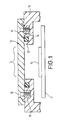
- Figure 1 shows a first vehicle entry transmitter of the prior art;
- Figure 2 shows a second vehicle entry transmitter of the prior art;
- Figure 3 shows a third vehicle entry transmitter of the prior art;
- Figure 4 shows a partial cross-section through a vehicle entry transmitter in accordance with a first embodiment of the present invention;
- Figure 5 shows a partial cross-section through the cap of the transmitter in Figure 4, and
- Figure 6 shows a partial cross-section of another embodiment of the invention.
-
- In the various figures like reference numerals indicate like parts.
- Referring first to Figure 1 which shows a cross section through a portion of a first vehicle entry transmitter, a
body portion 10 extends to define a cavity within which there is disposed acircuit element 11. - A part 12 of rigid plastics is disposed to cover an
opening 13 in thebody 10 for access to replacebattery 14. AnO ring 15 is disposed between two concentricupstanding portions Screws 13 maintain an inward bias against the O ring so that waterproofing is maintained, and these are secured into threadedmetal inserts 19. - Although this arrangement can provide a good waterproofing performance, it is expensive to implement, because of the cost of the screws and metal inserts to secure the screws and secondly because of the labour costs involved in assembly.
- Referring now to Figure 2 an
elastomeric operating member 22, has abutton 28 projecting through a hole in thecap 23. Alower portion 24 of the entry device body defines, in co-operation with theoperating member 22, a cavity within which thecircuit member 11 is disposed. Thelower portion 24 has an upstandingperipheral lip 25. Thecap 23 is retained in position against thelip 25 by the clipping action of ashaped flange portion 29 against thelip 25. Theelastomeric operating member 22 extends into a gap formed between alower wall portion 26 of the cap and anupper wall portion 27 of thelower portion 24. To aid retention of the elastomeric portion, either of thewalls barb portion 28. - Referring now to Figure 3, a third vehicle entry transmitter has a body formed of two
parts peripheral flange 33 with an inwardly-projectinglip portion 34 for clippingly engaging with acorresponding portion 35 of theupper part 31 to form a case. Anelastomeric operating member 36 in the form of an elastomeric button protrudes through a hole of theupper part 31 and has adownward protrusion 37 for operating thecircuit device 11. Thebutton 36 extends along the inner wall of theupper part 31 and is overmoulded to that wall to form a seal therewith. Thelower part 32 of the case has a furtherupstanding rib 38 which, when the two parts are clipped together, is urged against anend face 39 of the elastomer to retain it in place. - Referring now to Figure 4, the casing of a vehicle entry transmitter according to an embodiment of the invention comprises a lower part 41 and an
upper part 42. Both of these parts are made of hard plastics. The lower part 41, has anupstanding flange portion 43 spaced from the peripheral edge of the part with an outwardly-directed lip portion 44 at the distal end thereof. - The
upper part 42, or first casing part, is a generally cup-shaped body having a generallyplanar base portion 45 and aperipheral side wall 46. Anelastomeric body 47 extends along the inner wall of theupper part 42 and has anupstanding rib portion 48 extending from thebase wall 45. Aportion 50 disposed on the inside of theperipheral edge wall 46 is spaced from and co-operates with therib portion 48 to receive theupstanding flange portion 43 of the lower part 41, or second part of the casing. In this embodiment, theportion 50 is part of theelastomeric body 47 and is made of the same material. Thiselastomeric body 47 can also be used to form buttons through a hole in the upper part 42 (not shown in the figures). - The
portion 50 of the elastomeric body extends in an end region thereof to an inwardly-directedflange 51 so that the outwardly-directed lip portion 44 can be clipped into engagement with theupper part 42 and retained there by engagement between the lip portion 44 and theflange portion 51. - By comparison of Figure 4 and Figure 5, it will be seen that the spacing between the
rib portion 48 and theportion 50 is less than the width of theflange portion 43 with its lip portion 44, so that when theflange portion 43 of the lower part 41 is engaged with theportion 50 of the elastomeric body, therib portion 48 resiliently grips theflange portion 43. - Referring now to figure 6, it is shown another embodiment of the invention where the
portion 50 is part of theperipheral edge wall 46 of theupper part 42 and is in the same material: hard plastic. Theelastomeric body 47 extends along thebase wall 45 and presents anupstanding rib portion 48. The other characteristics of this embodiment are the same as those describe in the context of figure 4 : theportion 50 forms an inwardly-directedflange portion 51 from saidperipheral edge wall 46, and saidcounterpart flange portion 43 has an outwardly-directed lip 44 for co-operation with said inwardly-directedflange portion 51. - The
elastomeric body 47 is overmoulded onto the hard plasticsupper part 42 for a secure holding. - The hard plastics material of the
upper part 42 is nonetheless sufficiently flexible that pressure in the unsupported region of thebase 45 causes it to distort inwardly to engage the circuit for operation thereof. - It is possible to unclip the
upper part 42 to provide access to thebattery 14, for example to change the battery. - In an alternative embodiment the
upper part 42 does not form an operating member, but is merely a casing part, removable for battery access. - The device of the invention is advantageous in that a simple clip-together assembly is afforded.
- Although the invention has been described in the context of a vehicle entry transmitter, it is clear that other low voltage switching devices could use the same concept. Such devices include, for example, pagers and mobile phones and also external, switching devices such as interphones and security locks.
Claims (12)
- A water-resistant switching device having a casing, the casing having first (42) and second (41) parts, said first part having a base wall (45) and a peripheral edge wall (46), said device further comprising an elastomeric body (47) extending along said base wall (45) and forming an upstanding rib portion (48), wherein said rib portion (48) is spaced from and co-operates with a portion (50) disposed on the inside of side peripheral edge wall (46) to receive a counterpart flange portion (43) of the second part (41) of said casing.
- A water-resistant switching device as claimed in claim 1 wherein the portion (50) comes from the elastomeric body (47).
- A water-resistant switching device as claimed in claim 1 wherein the portion (50) is part of the peripheral edge wall (46).
- A water-resistant switching device as claimed in any preceding claim wherein said counterpart flange portion (43) has a thickness greater than said spacing, whereby when said counterpart flange portion (43) of said second casing part (41) is engaged with said portion (50), said rib portion (48) resiliently grips said counterpart flange portion (43).
- A water-resistant switching device as claimed in claim 1 to 3 or in claim 4 wherein said portion (50) forms an inwardly-directed flange portion (51) extending from said peripheral edge wall (46), and said counterpart flange portion (43) has an outwardly-directed lip (44) for co-operation with said inwardly-directed flange portion.
- A water-resistant switching device as claimed in any preceding claim wherein said elastomeric body (47) is secured to said first part (42) of said casing.
- A water-resistant switching device as claimed in claim 6 wherein said elastomeric body (47) is secured by overmoulding.
- A water-resistant switching device according to any preceding claim wherein said casing contains a circuit device, and said first part (42) of said casing is an operating member for said circuit device.
- A water-resistant switching device according to any preceding claim wherein said casing contains a battery, and said first part (42) of said casing is removable for changing said battery.
- An entry transmitter for a vehicle comprising a water-resistant switching device according to any preceding claim.
- A water-resistant switching device constructed and arranged substantially as herein described with reference to Figure 4, 5 or Figure 6 of the accompanying drawings.
- An entry transmitter for a vehicle constructed and arranged substantially as herein described with reference to Figures 4,5 or 6 of the accompanying drawings.
Applications Claiming Priority (2)
| Application Number | Priority Date | Filing Date | Title |
|---|---|---|---|
| GB9905725 | 1999-02-25 | ||
| GB9905725A GB2347269B (en) | 1999-02-25 | 1999-02-25 | Water-resistant switching device |
Publications (3)
| Publication Number | Publication Date |
|---|---|
| EP1032004A2 true EP1032004A2 (en) | 2000-08-30 |
| EP1032004A3 EP1032004A3 (en) | 2002-04-03 |
| EP1032004B1 EP1032004B1 (en) | 2004-10-20 |
Family
ID=10849521
Family Applications (1)
| Application Number | Title | Priority Date | Filing Date |
|---|---|---|---|
| EP00400458A Expired - Lifetime EP1032004B1 (en) | 1999-02-25 | 2000-02-17 | Water resistant switching device |
Country Status (4)
| Country | Link |
|---|---|
| US (1) | US6385045B1 (en) |
| EP (1) | EP1032004B1 (en) |
| DE (1) | DE60014989T2 (en) |
| GB (1) | GB2347269B (en) |
Cited By (4)
| Publication number | Priority date | Publication date | Assignee | Title |
|---|---|---|---|---|
| EP1280171A2 (en) * | 2001-07-26 | 2003-01-29 | Siemens Aktiengesellschaft | Keyboard |
| EP2166553A1 (en) * | 2008-09-17 | 2010-03-24 | Delphi Technologies, Inc. | Electric switch |
| EP3726552A1 (en) * | 2019-04-17 | 2020-10-21 | Premo, S.A. | A sealed electric switch asembly |
| US11688567B2 (en) | 2021-02-09 | 2023-06-27 | Premo, Sa | Waterproof switch assembly |
Families Citing this family (9)
| Publication number | Priority date | Publication date | Assignee | Title |
|---|---|---|---|---|
| DE10205951A1 (en) * | 2002-02-13 | 2003-08-21 | Cimosys Ag Goldingen | Control arrangement for mains-dependent devices operated with low-voltage electrical and provided with mains isolation |
| JP4124137B2 (en) * | 2004-02-23 | 2008-07-23 | 日産自動車株式会社 | Electronic unit housing |
| US7365278B2 (en) * | 2004-10-27 | 2008-04-29 | Lear Corporation | Vehicle occupant sensing system having a contamination barrier member |
| DE102005038687A1 (en) * | 2005-08-16 | 2007-02-22 | Siemens Ag | Housing system for electronic devices |
| US20070199804A1 (en) * | 2006-02-27 | 2007-08-30 | Cherry Corporation | Two part cleanable keyboard |
| GB0606988D0 (en) * | 2006-04-07 | 2006-05-17 | Bell Fruit Group Ltd | Entertainment machine button |
| JP5669774B2 (en) * | 2012-02-28 | 2015-02-18 | オムロンオートモーティブエレクトロニクス株式会社 | Switch device |
| FR3000837B1 (en) * | 2013-01-08 | 2016-04-22 | Legrand France | FACADE ASSEMBLY OF AN ELECTRICAL SWITCH AND ELECTRICAL SWITCH THEREFOR |
| US9224547B2 (en) * | 2013-11-25 | 2015-12-29 | GM Global Technology Operations LLC | Vehicle door window switch |
Citations (4)
| Publication number | Priority date | Publication date | Assignee | Title |
|---|---|---|---|---|
| US4047048A (en) * | 1976-04-12 | 1977-09-06 | General Motors Corporation | Master cylinder with combined reservoir cover, seal and fluid level sensor assembly |
| DE3818562A1 (en) * | 1988-06-01 | 1989-12-07 | Swf Auto Electric Gmbh | Electrical push-button switch, especially for switching on a reversing light of a motor vehicle |
| WO1993009553A1 (en) * | 1991-11-01 | 1993-05-13 | United Technologies Automotive, Inc. | Sealed housing for a remote switching device |
| US5822192A (en) * | 1995-06-20 | 1998-10-13 | Alps Electric Co. Ltd. | Case sealing structure and assembling method therefor |
Family Cites Families (8)
| Publication number | Priority date | Publication date | Assignee | Title |
|---|---|---|---|---|
| US3973099A (en) * | 1974-11-11 | 1976-08-03 | American Micro-Systems, Inc. | Push button switch for electronic watch |
| US3944761A (en) * | 1974-11-29 | 1976-03-16 | Nicholl Brothers, Inc. | Rotary switch |
| US4575004A (en) * | 1984-05-18 | 1986-03-11 | Geiger James E | Sprinkler system retrofit mechanism and method |
| US4905129A (en) * | 1988-10-13 | 1990-02-27 | Sharrah Raymond L | Flashlight with tail cap switch |
| US4918270A (en) * | 1989-03-06 | 1990-04-17 | Illinois Tool Works, Inc. | Appliance switch |
| US4940860A (en) * | 1989-07-07 | 1990-07-10 | Shiau Shoei Shuh | Waterproof switching device |
| JPH04104061A (en) * | 1990-08-23 | 1992-04-06 | Takata Kk | Acceleration sensor |
| US5282116A (en) * | 1993-02-10 | 1994-01-25 | Shiau Shoei Shuh | Flashlight |
-
1999
- 1999-02-25 GB GB9905725A patent/GB2347269B/en not_active Expired - Fee Related
-
2000
- 2000-02-17 EP EP00400458A patent/EP1032004B1/en not_active Expired - Lifetime
- 2000-02-17 DE DE60014989T patent/DE60014989T2/en not_active Expired - Lifetime
- 2000-02-25 US US09/513,700 patent/US6385045B1/en not_active Expired - Lifetime
Patent Citations (4)
| Publication number | Priority date | Publication date | Assignee | Title |
|---|---|---|---|---|
| US4047048A (en) * | 1976-04-12 | 1977-09-06 | General Motors Corporation | Master cylinder with combined reservoir cover, seal and fluid level sensor assembly |
| DE3818562A1 (en) * | 1988-06-01 | 1989-12-07 | Swf Auto Electric Gmbh | Electrical push-button switch, especially for switching on a reversing light of a motor vehicle |
| WO1993009553A1 (en) * | 1991-11-01 | 1993-05-13 | United Technologies Automotive, Inc. | Sealed housing for a remote switching device |
| US5822192A (en) * | 1995-06-20 | 1998-10-13 | Alps Electric Co. Ltd. | Case sealing structure and assembling method therefor |
Cited By (8)
| Publication number | Priority date | Publication date | Assignee | Title |
|---|---|---|---|---|
| EP1280171A2 (en) * | 2001-07-26 | 2003-01-29 | Siemens Aktiengesellschaft | Keyboard |
| EP1280171A3 (en) * | 2001-07-26 | 2005-01-05 | Siemens Aktiengesellschaft | Keyboard |
| EP2166553A1 (en) * | 2008-09-17 | 2010-03-24 | Delphi Technologies, Inc. | Electric switch |
| EP3726552A1 (en) * | 2019-04-17 | 2020-10-21 | Premo, S.A. | A sealed electric switch asembly |
| WO2020212406A1 (en) | 2019-04-17 | 2020-10-22 | Premo, Sa | Waterproof electric switch assembly |
| CN113692631A (en) * | 2019-04-17 | 2021-11-23 | 普莱默股份公司 | Waterproof electrical switch assembly |
| US11476062B2 (en) | 2019-04-17 | 2022-10-18 | Premo, Sa | Waterproof electric switch assembly |
| US11688567B2 (en) | 2021-02-09 | 2023-06-27 | Premo, Sa | Waterproof switch assembly |
Also Published As
| Publication number | Publication date |
|---|---|
| EP1032004A3 (en) | 2002-04-03 |
| GB2347269A (en) | 2000-08-30 |
| DE60014989T2 (en) | 2005-03-31 |
| DE60014989D1 (en) | 2004-11-25 |
| GB9905725D0 (en) | 1999-05-05 |
| EP1032004B1 (en) | 2004-10-20 |
| GB2347269B (en) | 2002-08-14 |
| US6385045B1 (en) | 2002-05-07 |
Similar Documents
| Publication | Publication Date | Title |
|---|---|---|
| EP1032004B1 (en) | Water resistant switching device | |
| EP1403534B1 (en) | Water-tight grommet | |
| US7144275B2 (en) | Water-resistant casing structure for electronic control device | |
| US9972457B2 (en) | Push switch | |
| US20040069658A1 (en) | Housing for an electronic key | |
| EP1783869B1 (en) | Connector | |
| JP5100591B2 (en) | Push-button switch | |
| US7759592B2 (en) | Seal for electrical switch pad | |
| US20040105567A1 (en) | Speaker installation structure | |
| JP5857997B2 (en) | Grommet | |
| JP4947179B2 (en) | Portable transmitter | |
| US20110308925A1 (en) | Push switch | |
| WO2016157793A1 (en) | Anchoring structure for annular member and electronic key | |
| US6313420B1 (en) | Slide switch | |
| JP2012253179A (en) | Electronic apparatus and cover member used in the same | |
| JPH11288635A (en) | Watertight structure of case | |
| JP4607697B2 (en) | Waterproof pushbutton switch device | |
| JP2010049887A (en) | Waterproofing structure of switch device | |
| US4291402A (en) | Plastic watch case | |
| CN110816685B (en) | Fuel tank housing or charging device housing with sealing assembly and vehicle body | |
| CN111656413A (en) | Electronic hand-held device, in particular radio key, with a sealing cap | |
| JP2007287560A (en) | Waterproof switch | |
| CN216081644U (en) | Instrument housing and instrument | |
| JPH08336224A (en) | Grommet | |
| KR100432748B1 (en) | Door switch for refrigerator |
Legal Events
| Date | Code | Title | Description |
|---|---|---|---|
| PUAI | Public reference made under article 153(3) epc to a published international application that has entered the european phase |
Free format text: ORIGINAL CODE: 0009012 |
|
| AK | Designated contracting states |
Kind code of ref document: A2 Designated state(s): AT BE CH CY DE DK ES FI FR GB GR IE IT LI LU MC NL PT SE Kind code of ref document: A2 Designated state(s): DE ES FR IT |
|
| AX | Request for extension of the european patent |
Free format text: AL;LT;LV;MK;RO;SI |
|
| PUAL | Search report despatched |
Free format text: ORIGINAL CODE: 0009013 |
|
| AK | Designated contracting states |
Kind code of ref document: A3 Designated state(s): AT BE CH CY DE DK ES FI FR GB GR IE IT LI LU MC NL PT SE |
|
| AX | Request for extension of the european patent |
Free format text: AL;LT;LV;MK;RO;SI |
|
| 17P | Request for examination filed |
Effective date: 20021004 |
|
| AKX | Designation fees paid |
Free format text: DE ES FR IT |
|
| RAP1 | Party data changed (applicant data changed or rights of an application transferred) |
Owner name: VALEO SECURITE HABITACLE |
|
| 17Q | First examination report despatched |
Effective date: 20030528 |
|
| RAP1 | Party data changed (applicant data changed or rights of an application transferred) |
Owner name: VALEO SECURITE HABITACLE S.A.S. |
|
| GRAP | Despatch of communication of intention to grant a patent |
Free format text: ORIGINAL CODE: EPIDOSNIGR1 |
|
| GRAS | Grant fee paid |
Free format text: ORIGINAL CODE: EPIDOSNIGR3 |
|
| GRAA | (expected) grant |
Free format text: ORIGINAL CODE: 0009210 |
|
| AK | Designated contracting states |
Kind code of ref document: B1 Designated state(s): DE ES FR IT |
|
| PG25 | Lapsed in a contracting state [announced via postgrant information from national office to epo] |
Ref country code: IT Free format text: LAPSE BECAUSE OF FAILURE TO SUBMIT A TRANSLATION OF THE DESCRIPTION OR TO PAY THE FEE WITHIN THE PRESCRIBED TIME-LIMIT;WARNING: LAPSES OF ITALIAN PATENTS WITH EFFECTIVE DATE BEFORE 2007 MAY HAVE OCCURRED AT ANY TIME BEFORE 2007. THE CORRECT EFFECTIVE DATE MAY BE DIFFERENT FROM THE ONE RECORDED. Effective date: 20041020 |
|
| REG | Reference to a national code |
Ref country code: IE Ref legal event code: FG4D |
|
| REF | Corresponds to: |
Ref document number: 60014989 Country of ref document: DE Date of ref document: 20041125 Kind code of ref document: P |
|
| PG25 | Lapsed in a contracting state [announced via postgrant information from national office to epo] |
Ref country code: ES Free format text: LAPSE BECAUSE OF FAILURE TO SUBMIT A TRANSLATION OF THE DESCRIPTION OR TO PAY THE FEE WITHIN THE PRESCRIBED TIME-LIMIT Effective date: 20050131 |
|
| ET | Fr: translation filed | ||
| PLBE | No opposition filed within time limit |
Free format text: ORIGINAL CODE: 0009261 |
|
| STAA | Information on the status of an ep patent application or granted ep patent |
Free format text: STATUS: NO OPPOSITION FILED WITHIN TIME LIMIT |
|
| 26N | No opposition filed |
Effective date: 20050721 |
|
| REG | Reference to a national code |
Ref country code: FR Ref legal event code: PLFP Year of fee payment: 17 |
|
| REG | Reference to a national code |
Ref country code: FR Ref legal event code: PLFP Year of fee payment: 18 |
|
| REG | Reference to a national code |
Ref country code: FR Ref legal event code: PLFP Year of fee payment: 19 |
|
| PGFP | Annual fee paid to national office [announced via postgrant information from national office to epo] |
Ref country code: DE Payment date: 20190211 Year of fee payment: 20 |
|
| PGFP | Annual fee paid to national office [announced via postgrant information from national office to epo] |
Ref country code: FR Payment date: 20190228 Year of fee payment: 20 |
|
| REG | Reference to a national code |
Ref country code: DE Ref legal event code: R071 Ref document number: 60014989 Country of ref document: DE |