BACKGROUND OF THE INVENTION
Field of the Invention
-
The present invention relates to filters for dividing
an input bandwidth into a plurality of channels and more
particularly, to a digital channelizer for satellite
communication applications using discrete Fourier
transformation (DFT) to divide the input bandwidth into
channels.
Description of the Prior Art
-
Digital channelizers in satellite communication systems
have several design constraints. High computation
complexity is required which requires highly complex
integrated circuit logic function and interconnections.
High power consumption by integrated circuits can lead to
high operating temperatures which could contribute to
channelizer malfunction or failure. The system clock rate
is required to be sufficiently high to support a high data
throughput but should be as low as possible to lessen power
consumption which contributes to the aforementioned possible
high operating temperatures. The power consumption of
a digital channelizer is proportional to the clock rate and
the type of integrated circuits which implement the required
high computational complexity. Furthermore, excess hardware
can interfere with processing efficiency and be a source of
potential malfunction.
-
Fig. 1 illustrates a block diagram of a prior art
digital channelizer 10 which functions as a down converter
and filter which divides a wideband input bandwidth into
a plurality of equally spaced channels. The channelizer 10
is representative of channelizers using DFT which have been
described in the literature. See Multirate Digital Signal
Processing, published in 1983 by Prentice Hall, Englewood
Cliffs, New Jersey, written by Crochiere and Rabiner, which
publication is incorporated herein by reference in its
entirety. Such systems have applications in wideband
satellite communication systems.
-
The INPUT signal is applied to a bandpass filter 12
which passes a selected wide bandwidth for division into N
equally spaced channels each of a narrower bandwidth. For
example, a wideband signal of 320 MHz. may be passed by the
bandpass filter 12 for division into sixteen 20 MHz. wide
channels. The bandpass filtered signal is applied to
analog to digital converter 14 which samples the bandpass
filtered signal. A representative frequency spectrum
resultant from sampling is described further below in
conjunction with Figs. 3A and 3B. Each sample is comprised
of a multiple bit word. A serial stream of multiple bit
words is outputted by the analog to digital converter 14 as
an input to demultiplexer 16 which produces D outputs 18.
The variable D may equal the variable M known as the
decimation rate. The demultiplexer 16 functions as a
multiple tapped delay line with each parallel output being
outputted from a different tap of the delay line. The
D outputs 18 of the demultiplexer are applied to window
presum computer 20. The window presum computer 20 functions
in a well-known manner to process the sequence of words
within a window of L words by multiplying each corresponding
word in a plurality of equal subparts R of the window
containing N words by a window presum function coefficient
and summing the resultant multiplication products to produce
the sum of the multiplication products where R=L/N. The
individual summed multiplication products, after further
processing including DFT as described below, are outputted
as individual ones of the N channels. The number of
outputted channels may be selected to be less than N.
-
For example, a sequence of ninety-six words, outputted
by the demultiplexer 16, is broken up into four subparts
each containing twenty-four words. Each of R corresponding
words, e.g. words 0, 24, 48 and 72, from a different
subpart, are multiplied by their preassigned window presum
function coefficient and summed to produce an output
summation which is subsequently processed into one of the
N output channels. The window presum computer 20 has
D inputs and N outputs. The relationship between M, D and
N, which is the DFT size and the number of possible
channels, affects the architecture of the window presum
computer 20. Words stored in a number of registers
(not illustrated), e.g. words 0, 24, 48 and 72, equal to the
R subparts in the window processed by the window presum
computer 20, are summed after multiplication by their
preassigned window presum function coefficient to produce
the output summation.
-
The window presum computer 20 has been implemented by
the Assignee with parallel data processing paths using
integrated circuits with M not being equal to N. The number
of processing paths I used by the Assignee to perform
parallel data processing satisfies the relationship I equals
the greatest common divisor of N and M which is expressed
hereafter as GCD(N,M).
-
The N outputs from the window presum computer 20 are
applied to a cyclic shift 24, which provides phase
adjustment, for processing into each channel by DFT. The
phase produced by the cyclic shift 24 is applied to the
resultant N word outputs from the window presum computer by
a calculated number of shifts. The operation of cyclic
shifting is well known and is, for example, described in the
aforementioned publication on pp. 320-323. The number of
shifts of the output words of the window presum computer 20
by the cyclic shift 24 is determined by computing the value
of the relationship mM*modulo N or -mM*modulo N. The
variable m is an output index variable which ranges from
zero upward to positive integers. The output from the
cyclic shift 24, which has N channels, is applied to
a discrete Fourier transform apparatus 26 having N inputs
which transforms the output from the cyclic shift 24 into
the N output channels.
-
Fig. 2 illustrates a conceptual block diagram of the
window presum algorithm which represents the window presum
processing performed by the system of Fig. 1. The sampled
output of L individual words is shifted into a shift
register which stores the sequential words outputted by the
analog to digital converter 14. The input data are shifted
into the shift register, which has a number of subparts R,
e.g. 4 in the above example. The number of words per
subpart (the DFT size) is equal to the number N of output
channels. The shift register has an analysis window L words
long which is R times the size N of the discrete Fourier
transform. The sum of the individual R subparts contains
the words which are further processed to individual channels
by DFT. The data in the shift register are weighed with
a time reverse window according to equation 7.70 on page 317
of the aforementioned publication to produce a windowed
sequence as illustrated. The sequence is processed as
blocks of samples starting at r=0 which are time aliased.
The resultant summation is processed by a cyclic shift 24
through a number of shifts equal to mM*modulo N or
-mM*modulo N and is applied to discrete Fourier
transform 26.
-
The analog to digital converter 14 of Fig. 1, in
accordance with digital sampling theory, produces a spectrum
of frequency domain signals centered about zero frequency as
illustrated in Figs. 3A and 3B which respectively illustrate
groups of twelve and twenty four frequency domain signals.
The sampling frequency of fs for real signals produces
counterpart frequency domain signals centered about the zero
frequency extending to fs/2 in both the positive (real) and
negative (conjugate) frequencies. The positive frequencies
may be expressed mathematically as a=x+iy and the negative
frequencies may be expressed as a=x-iy with corresponding
positive and negative frequencies being conjugates of each
other. Also, in accordance with digital sampling theory,
the frequency domain signals of Figs. 3A and 3B repeat
periodically with a period fs for successively higher
positive frequencies and successively lower negative
frequencies. These upper repeating frequency domain signals
have been omitted from the illustration. The counterpart
frequency domain signals of Fig. 3A are 1 and 11, 2 and 10,
3 and 9, 4 and 8, and 5 and 7, and the counterpart channels.
of Fig. 3B are 1 and 23, 2 and 22, 3 and 21, 4 and 20,
5 and 19, 6 and 18, 7 and 17, 8 and 16, 9 and 15, 10 and 14
and 11 and 13. Frequency domain signals 0 and 6 in Fig. 3A
and 0 and 12 in Fig. 3B do not have counterparts. The
information of each frequency domain signal is transformed
to its counterpart conjugate by a sign reversal of the
imaginary term iy.
-
Fig. 4A illustrates a diagram of the window presum
function of a window containing forty eight (L) real words
having four (R) subparts each containing 12(N) real words
and Fig. 4B illustrates a window presum function of a window
containing twenty four complex words containing an imaginary
part identified by the letter "i" following a number and
a real part identified by the letter "r" following a number.
The window presums are identical except that the window
presum function of Fig. 4B has half as many words in view of
each word having a real and a imaginary part. Complex data
in Fig. 4B is, for example, obtained when conversion of
a spread spectrum transmission is down converted in the
tuner of the receiver. The individual words of Figs. 4A and
4B are multiplied by their preassigned window presum
function coefficients and subsequently summed with other
products of corresponding words from other subparts to
produce the output of the window presum computation which is
subsequently processed into N channels by DFT.
-
Corresponding words in each subpart R are summed to
produce a number of sums equal to the number of words per
window, e.g. P0-P11 or P0r-P5i. The summations P0-P11 and
P0r-P5i; are processed with the window multiplication
process by the use of stored coefficients to compute a value
of y for each of the N channels which represents the
summation of products which is applied to the cyclic
shift 24.
-
The summation process, when the rate of decimation M is
equal to the number of channels N, may be implemented
efficiently with an array of registers storing the
individual words identified in the vertical columns of
Fig. 4A to produce the outputs P0-P11.
-
The summation of the products of corresponding
individual words (e.g. 0, 12, 24 and 36 in Fig. 4A or word
parts 0r, 6r, 12r and 18r in Fig. 4B) times their
preassigned window presum function coefficients may be
implemented in a number of ways. One method is illustrated
in Fig. 5 which has the disadvantage of using substantial
hardware requiring multipliers 40 and summation
calculation 42. The number of multipliers 40 is equal to
R and the number of adders in summation calculation 42 is
equal to (R-1) in the worst case. This method computes the
output summation y in one clock cycle (pipelined). The word
values x0, x1, x2 and x3 represent corresponding word values
from each of the R subparts of the window which is L words
in length, e.g. words 0, 12, 24 and 36 in Fig. 4A or real
word parts Or, 6r, 12r and 18r in Fig. 4B. While this
implementation for computing the summation y is
computationally fast, it has the disadvantage of requiring
a substantial number of gates, other hardware and
interconnections which have the disadvantages described
above especially in an environment involving satellites.
-
Fig. 6 illustrates a block diagram of a finite impulse
response filter proposed in "Applications of Distributed
Arithmetic to Digital Signal Processing: A Tutorial Review",
by Stanley A. White, in IEEE ASSP Magazine, July 1989,
pp. 1-19. The illustrated filter computes the summation y
with an input of four eight bit words x0, x1, x2, x3 in
a serial fashion requiring eight clock cycles to process
eight bit words. The overall operation is to compute
individual products of input words x0, x1, x2 and x3 and
their multiplying window coefficients W0, W1, W2, and W3 to
generate a sum Σi xiWi. The individual products are not
computed in isolation and then added. Each bit of every word
determines whether to add or subtract a multiple of their
respective window coefficients, and all the bits at the same
position within the words are processed at the same time.
The result is that the overall sum of products is generated
not by simply summing up products, but by summing multiples
of different sum combinations of window coefficients and
their negations. The bit select 50 selects bit slices from
the eight bit words, e.g. the bits of the least significant
bit LSB in ascending order to the most significant bit MSB.
The logic circuit 52 exploits symmetry in the DA ROM 54 to
eliminate half of the values that need to be stored for
distributed arithmetic to operate correctly as a process.
The process of reducing the number of bits is described on
pages 5 et. seq. in the aforementioned paper. The DA
(distributed arithmetic) ROM 54 stores all the possible sum
combinations of window coefficients and their negations.
The bit slice from the input words act as the address into
the DA ROM 54 to choose the proper sum of coefficients. The
shifter 56 outputs the proper multiple by a power of two of
the DA ROM output to the adder 58. The output of shifter 56
is applied to a summation calculation 58 which sums
multiples of different sum combinations of window
coefficients and their negations. Feedback from register 60
provides the current sum which is summed with the new sum by
summation calculation 58 for each successive bit slice.
-
The serial implementation of Fig. 6 suffers from the
disadvantage of requiring a high clock rate to compute the
summation y for large data words. A high clock rate in
satellite applications requires high energy consumption
which can cause heating in integrated circuits and for
systems requiring high data rates, represents a potential
speed processing barrier. Processing one bit at a time has
undesirable latency.
-
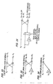
Fig. 7 illustrates an implementation of distributed
arithmetic used by the Assignee in the window presum
computer 20 to sum the products of the corresponding words
and their preassigned window presum function coefficient.
This system performs processing similar to Fig. 6, except
that three clock cycles are used to respectively process
four bit nibbles, which are inputted from twelve bit
words x0, x1, x2, x3. The processing of the four bit nibbles
is in parallel but otherwise is analogous to Fig. 5. The
summation calculation 62 sums for each of the three clock
cycles the outputs from the shifters 56. Register 64 stores
the resultant summation outputted by summation calculation
62 and feeds the summation back to the summation calculation
to sum the current summation with the summation of the next
clock cycle processing.
-
This implementation of distributed arithmetic has
disadvantages for high word processing throughputs. It
requires a higher clock rate to process the four bit nibbles
in three cycles for each word which increases energy
consumption when compared to processing all the bits of the
word in one cycle. The clock rate required to perform three
processing cycles per word could, for certain satellite
processing applications, limit the word processing
throughput below that which is required for a desired system
performance.
-
Window presum computers 20 are well known which utilize
an array of registers to store words x0, x1, x2, x3 processed
in accordance with the aforementioned processes for
computing the summation y. Some applications have their
decimation rate M equal to the DFT size N and the number of
channels which are outputted. However, the Assignee has
implemented a window presum calculator 20 having the
decimation rate M not equal to the DFT size N. These
systems provide the corresponding input words from each of
the aforementioned subparts of the window, e.g. words 0, 12,
24 and 36 from Fig. 4A or corresponding parts of words from
Fig. 4B from storage in registers for multiplication and
summation to produce the output y of the window presum
computer for each of the N channels.
-
Discrete Fourier transforms are well known. A stand
alone discrete Fourier transform apparatus of N inputs
provides a frequency response at N outputs at specific
equidistant frequencies. The N inputs are time domain
signals and the N outputs are frequency domain signals
determined at singular frequencies. The discrete Fourier
transform apparatus itself can extract channel information,
although it samples at only a singular frequency that
represents the channel information.
-
In a channelizer, an output does provide a single
extracted channel. The N outputs correspond to N time
domain signals that each contain information from one of
N frequency bands (equal in bandwidth) that divide the input
signal frequency spectrum. This does not exclude the input
signal from having more or fewer channels than N. The
spectrum is simply divided into N frequency bands. All
N inputs are required in the computation for every one of
the N outputs and each of the N outputs represents the time-domain
signal of one of the frequency bands dividing the
frequency spectrum.
-
Fig. 8 is a diagram representing a prior art discrete
Fourier transform device 118 which converts the output of
twelve cyclically shifted summations y, produced by the
cyclic shift 24, into twelve frequency domain outputs.
Various algorithms are known for computing a DFT. The
Winograd algorithm used for non-power of two discrete
Fourier transforms is used in Fig. 8. The DFT apparatus 118
has twelve time domain inputs "in 0-in 11" each representing
multiple bit words and twelve frequency domain outputs
"out 0-out 11" each representing multiple bit channel
outputs 0-11. Some of the outputs, which are represented in
Fig. 8 as real numbers, in fact are complex numbers
containing a real term and an imaginary term. The
illustration of complex input words has been omitted in
order to simplify illustration.
-
The discrete Fourier transform apparatus 118 includes
an input discrete Fourier transform computation stage 120
comprised of six two point DFT's 122 of known construction
each having a pair of time domain inputs and a pair of
frequency domain outputs, an intermediate discrete Fourier
transform computation stage 124 comprised of four three
point DFTs 126 of known construction each having three
inputs and three outputs and an output discrete Fourier
transform computation stage 128 comprised of six two point
DFTs 130 of known construction each having two inputs and
producing two frequency domain outputs. The outputs of the
two point DFTs 122 are inputs to the individual DFTs 126 of
the intermediate discrete Fourier transform computation
stage 124 and the outputs of the three point DFTs 126 of the
intermediate discrete Fourier transform computation stage
are inputs to the individual discrete Fourier transforms 130
of the output discrete Fourier transform computation
stage 128.
-
Fig. 9 illustrates a prior art pruned discrete Fourier
transform apparatus 140 which is representative of
modifications performed by the Assignee to eliminate
unnecessary DFTs 130 in the output discrete Fourier
transform computation stage 128 when all of the N possible
frequency domain outputs, equal to the number of time domain
inputs, are not needed for further processing. The discrete
Fourier transform 118 of Fig. 8 has been modified in Fig. 9
to eliminate two output stages 130 in view of only frequency
domain signals 2, 3, 4, 5 and 8, 9, 10 and 11 representative
of the frequency domain signals of Fig. 3A being required
for further processing. The two point discrete Fourier
transforms 130 which produce frequency domain signals 0
and 6 and 1 and 7 have been eliminated. The pairs of
frequency domain inputs 0 and 6 and 1 and 7 are not
represented. Output 5 is a counterpart and conjugate of
output 7. However, output 5 in Fig. 9 is not further
processed downstream in place of output 7.
-
Fig. 10 illustrates another form of prior art discrete
Fourier apparatus 300 having all possible frequency domain
signals as outputs. The frequency domain input discrete
Fourier computation stage 302 has three four point discrete
Fourier transforms 304 of known construction which each have
four time domain inputs and four outputs which respectively
are coupled to an output discrete Fourier transform
computation stage 304 having four three point DFTs 306.
This structure does not have and intermediate discrete
Fourier computation stage like Figs. 8 and 9.
-
Fig. 11 is a diagram representing a prior art discrete
Fourier transform apparatus 400 which is twenty four time
domain inputs and all of the possible twenty four frequency
domain outputs as outputs. The discrete Fourier transform
has an input discrete Fourier computation stage 402
comprised of three eight point preweaves 404, three
intermediate discrete Fourier computation stages, 410, 412
and 414, respectively comprised of eight three point
preweaves 416, a multiply stage and eight three point
postweaves 418 and an output discrete Fourier computation
stage 419 comprised of three eight point postweaves 420.
SUMMARY OF THE INVENTION
-
The present invention is a digital channelizer and
a method which divides an input bandwidth, such as the
wideband signal which is received by a satellite, into at
least some of N possible channels.
-
A digital channelizer in accordance with the invention
has an efficient architecture, organization and movement of
data from the window presum through the discrete Fourier
transform device. The decimation rate M is not limited to
being equal to N. The use of distributed arithmetic reduces
hardware required for the window presum operation compared
to the prior art of Fig. 5. An efficient layout of window
presum computations permits efficient cyclic shifts, which
map directly into the discrete Fourier transforms. The
output discrete Fourier computation stage may be simplified
when not all channels are required as outputs.
-
The digital channelizer includes a window presum
computer having a modular processing architecture which
transfers words stored within memory elements, which in the
preferred form of the invention is a connected array of
registers, in a systematic and periodic pattern to complete
window presum computations during a single clock cycle.
Minimizing the number of operations which must be performed
to complete the window presum operation reduces power
consumption and permits the system to operate at higher
throughputs. Furthermore, a modular implementation of
a window presum computer as parallel window presum circuits
simplifies the memory structure of the registers in the
window presum by permitting the same register array within
an integrated circuit to be used for each of the parallel
processing paths.
-
The window presum operation is performed in parallel in
modular window presum circuits which efficiently map into
the cyclic shift and discrete Fourier transform device which
are also implemented as a modular architecture. The number
of parallel paths, which is equal to the number of window
presum circuits, may be determined by the value of the
GCD(N,M). When the number of window presum circuits is
determined by the value of GCD(N,M), hardware use is reduced
in view of the processings from the window presum
computations, cyclic shifting and DFT being efficiently
mapped into a minimum amount of hardware. The processing
speed of each of the integrated circuits within the parallel
processing paths is at a lower clock rate. Parallel
processing within the window presum computer, cyclic shift
and discrete Fourier transform apparatus permits slower, but
more power efficient integrated circuit technologies, such
as CMOS, to be used to perform the required operations.
Slower parallel operations lessen the generation of heat
caused by high clock rates.
-
The window presum computer processes a block of words
produced by analog to digital conversion which have a data
length L. The data sequence is windowed by multiplying each
word by the preassigned window presum function coefficient
which is chosen to provide the filter requirement as, for
example, illustrated in Figs. 4A and 4B. Each of
R individual subparts of the window, which are N words long,
are processed word by word to provide products of the word
value times the preassigned window presum function
coefficient. While the invention is not limited thereto,
the preferred form of summing the individual products of the
words times the window presum function coefficients is with
distributed arithmetic which calculates the summation of the
products of words and their preassigned window presum
coefficients within a single clock cycle.
-
A window presum in accordance with the invention is
responsive to parallel data streams of words which are used
to produce N outputs for every M input words, which are
subsequently processed into N channels such that each
channel data rate has been decimated by a factor of M from
the original. The N outputs each are a function of a window
function and a function of a plurality of inputs to the
window presum.
-
A digital channelizer which divides an input bandwidth
into at least some of N channels in accordance with the
invention includes an analog to digital converter which
encodes the input bandwidth into a serial digital data
stream of words; a demultiplexer, coupled to the analog to
digital converter, which divides the serial digital data
stream into parallel data streams of data words; a window
presum, coupled to the parallel streams of data words,
responsive to a window presum function, storing L data words
in a window containing R subparts and outputting N outputs
which are each respectively capable of being processed into
a different one of the N channels, each of the N outputs
being a product of R words each respectively from
a different one of the R subparts and a coefficient of the
window presum function preassigned to each of the R words
from a different one of the R subparts with R=L/N and each
of the N outputs being calculated using distributed
arithmetic during a single clock cycle; and a discrete
Fourier transform apparatus, coupled to the N outputs of the
window presum, having N inputs and which performs a discrete
Fourier transform on the N inputs to output at least some of
the N channels.
-
A process for dividing an input bandwidth into at least
some of N channels in accordance with the invention includes
encoding the input bandwidth into a serial data stream of
words; dividing the serial data stream into parallel data
streams of data words; processing the data words of the
parallel data streams to produce products of data words and
a window presum function which are summed to produce
N outputs, the window presum function having a window
containing L data words divided into R subparts, each of the
N outputs being a product of R samples each respectively
from a different one of the R subparts and a coefficient of
the window presum function preassigned to each of the R
words from a different one of the R subparts with R = L/N
and each of the N outputs being calculated using distributed
arithmetic during a single clock cycle; and performing
a discrete Fourier transform on N inputs, which are coupled
to N outputs produced by processing the data words of the
parallel data streams to produce at least some of the
N channels.
-
It should be understood that the invention is not
limited to its elements as summarized above.
BRIEF DESCRIPTION OF THE DRAWINGS
-
- Fig. 1 illustrates a block diagram of a prior art
digital channelizer.
- Fig. 2 illustrates a processing diagram representative
of the processing of the prior art of Fig. 1.
- Figs. 3A and 3B respectively illustrate frequency
domain signals produced by digital sampling of wideband
signals in accordance with the prior art.
- Figs. 4A and 4B illustrate a prior art window presum
function containing respectively real and complex data
words.
- Fig. 5 illustrates a prior art hardware implementation
for calculating a window presum for individual corresponding
words in accordance with the window presum function of
Fig. 4A.
- Fig. 6 illustrates a prior art hardware implementation
for providing a finite impulse response filter function.
- Fig. 7 illustrates a prior art hardware implementation
for calculating a window presum of individual corresponding
data words in accordance with the window presum function of
Fig. 4A.
- Fig. 8 illustrates a first type of prior art discrete
Fourier transform apparatus.
- Fig. 9 illustrates a prior art pruning of the discrete
Fourier transform apparatus of Fig. 8.
- Fig. 10 illustrates a second type of prior art discrete
Fourier transform apparatus.
- Fig. 11 illustrates a third type of prior art discrete
Fourier transform apparatus.
- Fig. 12 illustrates a block diagram of the present
invention.
- Fig. 13 illustrates a block diagram of a window presum
computer in accordance with the present invention.
- Figs. 14-16 illustrate an embodiment of the individual
window presum circuits of the window presum computer of
Fig. 13.
- Fig. 17 illustrates a block diagram of a preferred form
of distributed arithmetic used in the window presum computer
of Figs. 12-16 with the practice of the present invention.
- Fig. 18 illustrates a block diagram of a preferred
embodiment of a cyclic shift in accordance with the present
invention.
- Fig. 19 is a table illustrating cyclic shifts of the
cyclic shift of Fig. 18 required for the outputs of the
window presum circuits of Figs. 14-16 of the present
invention.
- Fig. 20 is a first embodiment of a pruned discrete
Fourier transform apparatus in accordance with the present
invention.
- Fig. 21 is a second embodiment of a pruned discrete
Fourier transform apparatus in accordance with the present
invention.
- Fig. 22 is a block diagram of an embodiment of
a discrete Fourier transform apparatus in accordance with
the present invention which calculates the transformation of
real or complex data inputs with a processing architecture
which is configured to transform real or complex data in
response to command.
- Fig. 23 is a block diagram of a two-point discrete
Fourier transform/recombine for processing real data.
- Fig. 24 is a block diagram of a two-point discrete
Fourier transform/recombine for recombining complex data.
- Fig. 25 is a block diagram of mulitplication by -j
(a twiddle factor) of an output of one of the three point
discrete Fourier transforms of Fig. 22.
- Fig. 26 is a block diagram of an embodiment of a two
point discrete Fourier transform/recombine which performs
the operations of Figs. 23-25.
-
-
Like reference numerals identify like parts throughout
the drawings.
DESCRIPTION OF THE PREFERRED EMBODIMENTS
-
Fig. 12 illustrates a block diagram of a digital
channelizer 100 in accordance with the present invention.
Differences between the embodiment 100 of Fig. 4 and the
prior art of Fig. 1 are that the window presum computer 102
is implemented as a plurality of parallel window presum
circuits WP1, WP2 and WP3, which may vary in number in
accordance with window presum processing requirements and
the cyclic shift 24' and discrete Fourier transform
apparatus 26' have been modified to a similar parallel
architecture to provide high speed calculation with lower
power consumption and simplified hardware requirements. The
window presum circuits WP1, WP2 and WP3 each perform
processing in parallel to implement the functions of the
window presum computer 20. The number of window presum
circuits I is preferably equal to GCD(N,M), which for the
example of M=15 and N=24 makes I=3, which results in an
efficient deployment of hardware operating at a lower clock
speed in the individual parallel processing paths of data in
the window presum circuits WP1, WP2 and WP3, cyclic
shift 24' and discrete Fourier transform apparatus 26' as
described below which is important in satellite
applications.
-
The window presum computer 102 implemented as
a plurality of window presum circuits operating in parallel
permits a lower clock rate in each window presum circuit.
As a result, slower integrated circuit technologies may be
used to implement all of the processing in the I parallel
data processing paths extending from the window presum
circuits WP1, WP2 and WP3 through the discrete Fourier
transform apparatus 26' as described below which consume
less power, such as CMOS circuits.
-
Parallel processing achieves a high throughput data
rate of window presum processing of words required to
perform the complete window presum computer function in
a wide band satellite application. In view of a preferred
embodiment of the present invention being in a satellite,
it is highly desirable to lessen heat generating energy
consumption resultant from a high clock rate in the window
presum computer 102, the cyclic shift 24' and discrete
Fourier transform apparatus 26' which is accomplished by
implementation of the window presum computer, cyclic
shift and discrete Fourier transform apparatus in a parallel
architecture in a low-power consuming technology (such as
CMOS).
-
Fig. 13 illustrates a block diagram of the three window
presum circuits WP1, WP2 and WP3 which comprise the window
presum computer 102. The use of I parallel processing paths
within the window presum computer 102, the cyclic shift 24'
of Fig. 12 as described below in conjunction with Figs. 18
and 19 and the I parallel processing paths within the
discrete Fourier transform apparatus 26' as described below
in conjunction with Figs. 20-22 is a highly efficient
hardware implementation. The number D of parallel paths of
input data from the demultiplexer 16 (also equal to M the
decimation rate in this instance) is 15 with input data
words "in_wp_0" thru "in_wp_14" each comprised of multiple
bits being shifted into the window presum circuits 102
during one clock cycle. The decimation rate M is not
necessarily equal to a number of branches in the
demultiplexer 16. Each of the window presum circuits 102
performs window presumming, described below in detail in
conjunction with Figs. 14-17, to output for each clock
cycle N output words "out_wp_0" thru "out_wp_23" which
represent the N channels which are produced by the digital
channelizer or with a reduced number of channels produced by
pruning the DFT structure as described below in conjunction
with Fig. 21 which is used within a channelizer. Each of
the output words y(i), which are inputs to the cyclic
shift 24', is a function of the window presum function
calculated by the sum of products of stored coefficients for
each of the corresponding R input words with the
corresponding input words respectively from the parallel
inputs of one of the I groups of input words and summing
those R words together.
-
Figs. 14-16 respectively illustrate an implementation
of each of the individual window presum circuits WP1, WP2
and WP3 of Fig. 13. The window presum circuits 200 are
identical, permitting their use in a modular architecture.
Each window presum circuit has a number L' of registers
equal to the number of data points in each of the I groups
wherein:
L'= L GCD(N,M)
-
In the window presum circuits 200 in Figs. 14-16, input
data words are shifted through registers which are connected
in a group of R registers to individual distributed
arithmetic functions 202 (DA#1-DA#24) which process the
input data words to compute the individual products of each
data word and its stored window presum function coefficient
followed by a summation of the products which is outputted
as the data words y(i). The calculation of the
summation y(i) does not require the use of distributed
arithmetic. However, preferably the calculation of the
summation y(i) is performed with distributed arithmetic.
A preferred implementation of the calculation of y(i) with
distributed arithmetic is described below in conjunction
with Fig. 17 which requires only a single clock cycle to
complete the calculation of each value of y(i). The
parallel processing of each of the window presum circuits
lowers the clock rate permitting energy efficient integrated
circuit implementations such as CMOS to be used.
-
The individual numbers appearing inside of the
rectangular boxes, representing registers, identify
particular stored data words in a data sequence in a window
which is L words long, e.g. 96. Each of the words may have
any number of bits. Additionally, buffering registers 204
are provided where time shifting for a clock cycle is
necessary. The input words are identified by the legend
"in_wp_" followed by a number and output words, which are
outputted for each clock cycle, are identified by the legend
"out_wp_" followed by a number.
-
Each of the outputs y(i) of the window presum circuits
of Figs. 14-16 is a function of a window presum function and
data words from a plurality of the parallel data streams
which are inputs "in_wp" thereto that are the outputs from
the demultiplexer 18. The calculation of each output y(i)
is described in further detail below in conjunction with
Fig. 17. For example, with reference to Fig. 14, input word
"in_wp_12" is coupled to register 87 which is directly
coupled to a distributed arithmetic calculator DA#2 and is
an input to register 72 which is directly coupled to DA#1.
Furthermore, input word "in_wp_3" is directly coupled to
register 93 which is coupled to register 78 which is coupled
to register 63 which is coupled to register 48 which is
directly coupled to DA#1. Therefore, the word output y(i)
"out_wp_0" is a function of "in_wp_12" and "in_wp_3", as
well as being a function of input words "in_wp_9" and
"in_wp_0". Furthermore, the number of R inputs respectively
from R different registers coupled to each distributed
arithmetic function or circuit 202 is equal to the number of
subparts of the window of L words processed by the window
presum function which each contain N words. Similarly, the
outputs of the other distributed arithmetic functions or
circuits 202 are a function of a plurality of input words
respectively from R different registers.
-
As may be seen, corresponding words stored in each of
the R subparts are inputs to the distributed arithmetic
function 202, e.g. DA#1 has R inputs. Each distributed
arithmetic function 202 produces a sum y(i) of four weighted
products. The different sums y(i) are also identified as
output words "out_wp_0-out_wp_23". Each output y(i)
mathematically represents the sum value of each of the input
words multiplied by that word's preassigned individual
window presum function coefficient of the filter, such as
the filter functions illustrated in Figs. 4A and 4B.
-
Certain relationships define a preferred window presum
computer 102 implementation in accordance with the present
invention. The window presum has N outputs which are equal
in number to the number N of possible output channels
produced by the digital channelizer and the number of points
in the discrete Fourier transform apparatus 26'. The window
presum computer 102 as described has a total of D inputs
which is equal to M, the decimation rate, and represents the
number of data words which are inputted to the window presum
computer during each clock cycle. However, the invention is
not limited to embodiments in which D equals M.
-
It should be understood that the clock circuit utilized
in the register implementation of Figs. 14-16 has been
omitted for purposes of simplicity and operates at a slower
speed than the serial input data rate because of the
parallel operation of the window presum circuits WP1, WP2
and WP3.
-
The window presum computer 102 comprises I window
presum circuits with I equal to GCD(N,M). Each window
presum circuit is responsive to a different one of the
groups of data words. As may be seen, the data words, which
are inputs to Fig. 14, are data words 0, 3, 6, 9 and 12; the
data words which are inputs to Fig. 15 are data words 1, 4,
7, 10 and 13; the data words which are inputs to Fig. 16 are
data words 2, 5, 8, 11 and 14. The data words y(i) which
are outputs from Fig. 14 are data words 0, 3, 6, 9, 12, 15,
18 and 21; the data words y(i) which are outputs from
Fig. 15 are data words 1, 4, 7, 10, 13, 16, 19 and 22; and
the data words y(i) which are outputs from Fig. 16 are data
words 2, 5, 8, 11, 14, 17, 20 and 23. Each window presum
circuit WP1, WP2 and WP3 is responsive to a different one of
the groups of the aforementioned data input words and
produces N' outputs with each of the N' outputs being
a function of the window presum function, as illustrated,
for example, in the prior art of Figs. 4A and 4B, and
a plurality of the data input words with N' not being equal
to M and the ratio of N/N'=I.
-
The window presum circuits 200 are useful in a modular
architecture. Consumption of power is reduced. Undesirable
heating of integrated circuits, which is disadvantageous for
applications such as satellites, is lessened which is
a primary field of application of the present invention.
Data processing in each of the window presum circuits is
identical, systematic and in a periodic pattern which allows
operations performed by each of the individual window presum
circuits WP1, WP2 and WP3, which are preferably integrated
circuits, to perform identical processing with each clock
cycle. Identical standard window presum circuits
implemented in a modular parallel architecture allow the
clock rate of the window presum computer 102 to be lowered
which lowers power consumption. The number of operations
performed to complete the window presum operation is
reduced. Interconnect and logic complexity required to
perform presum operations is reduced.
-
Fig. 17 illustrates a preferred embodiment 202 of
distributed arithmetic which may be used with the practice
of the present invention. However, it should be understood
that the present invention is not limited to the use of
distributed arithmetic in the practice of the window presum
computer 102 of the present invention nor to the preferred
embodiment of distributed arithmetic of Fig. 17. The prior
art of Fig. 5 is a possible implementation for calculating
y(i) without distributed arithmetic.
-
The inputs x0, x1, x2, and x3 represent eight bit words
which are inputted to the individual distributed arithmetic
functions or circuits 202 of Figs. 14-16. A number of
parallel processing paths 203, equal to the number of bits
within each word x0, x1, x2, and x3, perform the calculations
which are summed as the quantity y(i) which is the output
from each of the distributed arithmetic functions or
circuits 202. Each processing path 203 is comprised of
logic 52, distributed arithmetic ROM 54 and shifter 56 which
perform functions analogous to the prior art of Fig. 6 but
accomplish all processing within one clock cycle instead of
with multiple clock cycles as in Fig. 6. Each processing
path 203 processes a single different bit slice from the
R input data words outputted from the registers of
Figs. 14-16. As illustrated in Fig. 17, eight different bit
slices are processed respectively during one clock cycle by
the different processing channels 203.
-
The logic functions 52 reduce the number of bits by one
which are inputted as addressing bits to the distributed
arithmetic ROMs 54 which output a precalculated sum of the
coefficients which is addressed by the bits within the bit
slice of each of the bits of the bit slice. The shifter 56
multiplies the output by the weighting factor 2n or 2-n to
output the correct total for the position of the particular
bit slice, e.g. paths 0-7 to the carry save adder 65 which
outputs the total y, representing the individual
outputs y(i) of each of the distributed arithmetic functions
or circuits 202 of Figs. 14-16.
-
The distributed arithmetic architecture 202 of Fig. 17
has substantial advantages in an environment which has
processing constraints such as a satellite application. The
use of only parallel processing for each bit slice
(e.g. 0-7) reduces the system clock rate which permits
circuits such as CMOS to be used, which is a preferred
integrated circuit implementation for reducing power
consumption in integrated circuits used in accordance with
the present invention. The use of CMOS and other integrated
circuit technologies which lower power consumption can
provide increased processing capability by lowering
operating temperature of the integrated circuits.
Furthermore, fewer gates are required to implement the
distributed arithmetic 202 of Fig. 17 in comparison to the
prior art of Fig. 5.
-
Figs. 18 and 19 illustrate the implementation of
a preferred embodiment of the cyclic shift 24' used in
a digital channelizer in accordance with the invention in
which divides an input bandwidth into at least some of
equally spaced N channels. The cyclic shifting function of
the present invention performs the same function as in the
prior art but is implemented in a modular architecture of
integrated circuits, such as CMOS, in a parallel data
processing architecture. The cyclic shift 24', as
illustrated in Fig. 18, includes I parallel cyclic shifting
paths which are identical in number to the I window presum
circuits utilized in a preferred embodiment of a window
presum computer 102 in accordance with the present
invention. The use of same number of parallel processing
paths in the window presum computer 102 and in the cyclic
shift 24' permits a highly efficient interconnection between
the window presum computer 102 and the cyclic shift which
increases the efficiency of the cyclic shift 24' and
substantially reduces power consumption in a digital
channelizer in a satellite application, such as a multibeam
regenerative wideband satellite system. Each cyclic shift
path 500 is responsive to a different input group of data
words which correspond to the data words outputted by the
window presum computer in I (three) groups as illustrated in
Fig. 13. The I cyclic shift paths 500 produce I output
groups of data words 504 as illustrated on the right hand
side of Fig. 18. The outputs of data words 504 from the
cyclic shift paths 500 are inputs to the discrete Fourier
transform apparatus used in practice of the present
invention which may be in accordance with the prior art of
Fig. 11 or in accordance with the discrete Fourier transform
apparatus of Fig. 21 which prunes certain outputs from the
output Fourier transform computation stage 419 where all
frequency domain outputs are not necessary for subsequent
processing into channels by the channelizer. Each cyclic
shift path 500 has a number of barrel shifters 502 which is
equal to the number of inputs thereto, from the
corresponding window presum circuit 200 of the window presum
computer 102. The inputs to each of the barrel shifters 502
to the right of the barrel shifters having the outputs wp-0,
wp-1 and wp-2 in each of the I cyclic shift paths 500 are
rotated one position so that the identified output
represents the top input but the order of the inputs is
unchanged. For example, the barrel shifter 502 having the
output wp-15 has its inputs out-wp from top to bottom in the
order 15, 6, 21, 12, 3, 18, 9 and 0 and the barrel shifter
immediately to the right has its inputs out-wp in the order
6, 21, 12, 3, 18, 9, 0, 15.
-
The number of cyclic shift paths is equal to GCD(N,M).
Each output group 504 of data words is shifted through
a number of cycles Q equal to N/GCD(N,M). The number of
cycles used by the cyclic shift 24', e.g. 8, determines the
number of outputs of the window presum circuits 202 which
are grouped together and permits direct mapping of
interconnections from the window presum circuits 200 into
the parallel cyclic shift paths 500. Each cycle has a shift
value defined by mM*modulo N or -mM*modulo N with m varying
from zero to Q-1. The foregoing number of cycles and shift
values produce an efficient cyclic shift 24' of a parallel
architecture which has inputs which efficiently map to the
outputs of the window presum circuits 102 and into the
inputs of the discrete Fourier transform apparatus 26'
without complex interconnections.
-
Fig. 19 illustrates a table containing the various
cycle values for the eight cycles through which each of the
word outputs of the barrel shifters 502 are shifted in each
of the cyclic shift paths 500. The headings 0-23
respectively indicate for each of the eight cycles the
output value of the barrel shifters 502 identified by the
headings 0-23 which are the input words to individual cyclic
shift paths 500 to the left in Fig. 18. As may be seen, the
parallel cyclic shift paths 500 from top to bottom
respectively have input words in a first group of 0, 15, 6,
21, 12, 3, 18 and 9, in a second group of 1, 16, 7, 22, 13,
4, 19 and 10 and in a third group of 2, 17, 8, 23, 14, 5, 20
and 11. The first group of 0, 15, 6, 21, 12, 3, 18 and 9
represents the calculated result of mM modulo N for M
equalling 15, N equalling 24 and m varying from 0 to 7.
When the outputs of the window presum computer 102 produced
by the window presum circuits 200 are chosen in this order,
the interconnection between the window presum computer 102
and the cyclic shift 24' is simplified. The choice of the
order of the words in the second and third groups is in
accordance with the same sequence as used in the first group
except that each word value is augmented by one in group two
relative to group one and is augmented by two in group three
relative to group one. Therefore, the required relative
shifting of the output between subsequent words in each
group is identical and is maintained which permits the
shifting of the parallel cyclic paths 500 to be driven by
a modulo eight (3 bit) counter 506 toggled at the clock
rate.
-
As illustrated with the outputs 504 from the cyclic
shift 24' it is possible to enable the cyclic shift outputs
to efficiently map into the inputs of the discrete Fourier
transform apparatus 26' such as in Fig. 21. The cyclic
shift paths 500 produce outputs that are independent of a
first stage discrete Fourier transform which allows hardware
design replication in a parallel architecture. This
efficient mapping occurs when the first discrete independent
Fourier transform computation stage contains GCD(N,M)
discrete Fourier transforms each having Q input points and
the prime factor algorithm is used which causes the ordering
of the discrete Fourier transform to be such that the
outputs 504 may be mapped with simple interconnection into
the inputs of the discrete Fourier transform such as that
illustrated in the prior art of Fig. 11 and the pruned
discrete Fourier transform described below in conjunction
with Fig. 21. Other efficient mappings may offer similar
simple interconnection characteristics.
-
The actual output values in Fig. 19 for each of the
barrel shifters identified by the headings 0-23 of the
cyclic shift paths 500 are obtained by identifying the
particular shift cycle of the repeating cycles 1-8.
Therefore, it is seen that the barrel shifter identified
with the heading 15 sequentially for cycles 1-8 outputs
inputs identified by out_wp 15, 6, 21, 12, 3, 18, 9 and 0,
respectively.
-
The individual cyclic shift paths 500 contain Q barrel
shifters 502 which function as word shifting elements. Each
barrel shifter 502 is responsive to an identical group of
input words 503 identified by the legend "out_wp" followed
by a number and outputs only a single word at a time. The
present invention is not limited to barrel shifters to
implement the cyclic shift 24' with any circuit or process
which can output the word values for the cycle inputs of
Fig. 19 being usable in the practice of the invention.
-
Fig. 20 illustrates a first embodiment 600 of a pruned
discrete Fourier transform apparatus in accordance with the
present invention which represents a modification of the
prior art discrete Fourier transform of Fig. 10. Pruning
results in the number of actual outputs P of the discrete
Fourier transform being less than a possible number of
outputs. Pruning of a discrete Fourier transform reduces
computational complexity both in terms of logic complexity
and interconnection complexity. Furthermore, pruning also
reduces power consumption. Any operations used to generate
inputs to the pruned portion of the discrete Fourier
transform apparatus can be eliminated from the input
discrete Fourier transform stage.
-
The discrete Fourier transform apparatus 600 represents
the circumstance where only output frequency domain
signals 2, 3, 4, and 5 are required for subsequent
processing from inputs from the cyclic shift 24'. The three
point DFT 306' which contains an "X" is unnecessary in view
of output frequency domain signal 7 being used in place of
frequency domain signal 5 for processing by processing
device 602 which represents any downstream processing of the
discrete Fourier transform including, but not limited to,
applications in a digital channelizer. For real input
signals frequency domain signal 7 is a conjugate of
frequency domain signal 5, which is not provided in an
output of the three remaining three point discrete Fourier
transforms 306. However, because frequency domain signal 7,
as illustrated in Fig. 3A, is a conjugate of frequency
domain signal 5, which is not present in the output from the
discrete Fourier transform apparatus 600, a sign negation of
the imaginary part of the frequency domain signal 7 permits
the information of frequency domain signal 5 to be recovered
and available for downstream processing while permitting the
discrete Fourier transform apparatus output(s) to be
simplified which has the above-stated advantages.
-
A discrete Fourier transform apparatus in accordance
with the invention has at least one discrete Fourier
transform computation stage. However, in a preferred
embodiment the discrete Fourier transform includes multiple
computation stages 302 and 305', as illustrated in Fig. 20,
and, 402, 410, 412, 414 and 419 as illustrated in Fig. 21,
as discussed below. While the example illustrated in
Fig. 20 represents only the use of frequency domain signal 7
in place of frequency domain signal 5, it should be
understood that each of the N inputs which have conjugates
(e.g. frequency domain signals 0 and N/2 (for even N) do not
have conjugates) may be represented in the output by its
conjugate which is subsequently processed in place of the
frequency domain signal which is not an actual output.
Furthermore, at least one processing device 602 may be used
to process at least one conjugate as representative of one
of the input signals.
-
Fig. 21 illustrates another embodiment of a discrete
Fourier transform apparatus 700 in accordance with the
present invention in which two conjugates of the frequency
domain signals illustrated in Fig. 3B are processed as
representative of inputs. The difference between the prior
art of Fig. 11 and the discrete Fourier transform
apparatus 700 resides in the elimination of one of the eight
point postweaves 420 which permits channels X[16] and X[19]
to be used in place of their conjugate frequency domain
signals X[8] and X[5] which are not outputs in view of the
elimination of the third eight point postweave 420 contained
in Fig. 11. The processing devices 702 process the
transformation of the plurality of conjugates of the twenty-four
inputs, which are not transformed into an actual
output, in place of the plurality of the twenty-four inputs
which are not transformed into an actual output. As
a result, the overall structure of the discrete Fourier
transform apparatus 700 is simplified in that the output
discrete Fourier transform computation stage has an eight
point postweave 420 pruned therefrom which lessens power
consumption and further reduces the amount of hardware in an
application where all of the twenty four possible output
channels in a channelizer are not required.
-
Fig. 22 illustrates a modification of the circular
shift 24' and discrete Fourier transform apparatus 26' as
illustrated in Fig. 12 under the control of an input command
specifying the processing of real or complex data. The
command permits real word inputs or complex word inputs to
be transformed into channel outputs of a channelizer without
external modification of the cyclic shifts 24' and the
discrete Fourier transform 26'. In the left-hand portion of
Fig. 22, the headings "complex" and "real" respectively
identify the selective inputting of twelve data points. The
data listed under the heading "complex", signify the real
and imaginary parts of six words and, the data listed under
the heading "real", signify the real data of twelve input
words.
-
The cyclic shift 24' is comprised of twelve barrel
shifters (multiplexers) 700 which receive inputs that
correspond to the data under the "real" heading. However,
it should be understood that if complex data is being
inputted, that that data is identified by the words "w0r"'
through "w5i". The actual input values are either
represented by the imaginary or real component of complex
data or real data. The barrel shifters 700 have outputs
which, depending upon the particular barrel shifter, are
either coupled directly to a two point discrete Fourier
transform 702 or an input to switch 704. The switches 704
each have at least one input receiving real data as
identified by the words W4, W10, W8, W2, W9, W3, W1, and W7
and at least one input receiving a component of complex data
as identified by inputs W4r, W1r, W2r, W5r, W0i, W3i, W4i and
W1i. The input to each of the switches 704, REAL/COMPLEX
SELECT is a command which specifies processing of the
cyclically shifted real data or the cyclically shifted
complex data outputted to the barrel shifters 700 by the
cyclic shift 24'. The discrete Fourier transform
apparatus 26' is comprised of an input discrete Fourier
computation stage 720 comprised of six two-point discrete
Fourier transforms 702 and four three-point discrete Fourier
transforms 706 and an output stage 728 comprised of six two-point
discrete Fourier transforms/recombines 708. In real
processing mode, the two point discrete Fourier
transforms/recombines 708 function as two point discrete
Fourier transforms and as two point recombines in complex
mode. The individual outputs from the output stage 728 are
always complex data but, depending upon whether the
REAL/COMPLEX SELECT command specifies the processing of real
or complex data, the number and order of complex outputs is
changed.
-
The architecture of the cyclic shift 24' and the
discrete Fourier transform apparatus 26' of Fig. 22 permits
modular construction in diverse applications in which it is
desirable to selectively input to discrete Fourier transform
apparatus 26' either real or complex data outputs from a
window presum computer 102 without having to modify the
cyclic shift 24' and discrete Fourier transform apparatus
26'. The only variable in the operation of Fig. 22 is the
command REAL/COMPLEX SELECT to transform the inputs to the
cyclic shift 24' as either real data or complex data.
A universal architecture for discrete Fourier transforming
of real or complex data may be implemented in integrated
circuits to process data in parallel processing
architectures such as that of the present invention. While
Fig. 22 is illustrated as processing as inputs the output
from a twelve point window presum calculation, it should be
understood that the configuration of Fig. 22 may be modified
to parallel architectures, such as the eight point
processing of the parallel channels described above.
-
The following relationships exist for the discrete
Fourier transform apparatus 26' of Fig. 22. N is a multiple
of two. The N point discrete Fourier transform
apparatus 26' includes an input discrete Fourier computation
stage 724 which is required to have two N/2 point Fourier
transforms 702 and an output discrete Fourier computation
stage 728 which is required to have N/2 two-point discrete
Fourier transforms/recombines 708. The two point discrete
Fourier transforms/recombines 708 are two point discrete
Fourier transforms in real mode and two point recombines in
complex mode as described in more detail below. The
architecture of the discrete Fourier transforms/recombines
708 as two point structures enables them to function in real
and complex mode.
-
In order to permit operations in real and complex mode,
the discrete Fourier transforms/recombines 708 contain
identical hardware. The discrete Fourier
transform/recombine 708 functions in a configurable manner
which configuration depends upon the type of data being
processed and the location in the output discrete Fourier
transforms stage 728 in Fig. 22.
-
Real processing is illustrated in Fig. 23 during which
only real data is subjected to discrete Fourier
transformation.
-
In a complex data processing mode, as illustrated in
Fig. 24, one complex input is combined from the N/2 point
discrete Fourier transforms 702 that process the "real"
inputs, while the other complex input will come from the N/2
point discrete Fourier transforms 702 that process the
"imaginary" inputs. The "imaginary" value must be
multiplied by j (equivalent to i mathematically). Then, the
individual components of the "real" and "imaginary" values
are added to achieve the final output.
-
In the implementation of the twelve point discrete
Fourier transform apparatus 26' (in the 2-3-2 architecture),
the outputs of one of the three point discrete Fourier
transforms 706 requires a multiplication by -j (a twiddle
factor) prior to the final two point discrete Fourier
transform/recombine 708. This multiplication operation is
performed by the two point discrete Fourier
transform/recombine 708 as shown in Fig. 25 as (real case-special).
-
The bottom three two-point discrete Fourier
transform/recombines 708 in Fig. 22 (which have their lower
input from the bottom-three point discrete Fourier
transforms 706), provide a multiplication by -j in the case
of real data processing.
-
The design of the two point discrete Fourier
transforms/recombines 708 must incorporate all possible
operations, including two point discrete Fourier transform,
two point discrete Fourier transform with -j multiplication,
and two point complex recombine function. A high level
diagram of a discrete Fourier transform 708 performing all
of these functions is illustrated in Fig. 26 and shows that
all output combinations are attainable.
-
While the invention has been defined in terms of
preferred embodiments, it should be understood that numerous
modifications may be made thereto without departing from the
spirit and scope of the present invention. It is intended
that all such modifications fall within the scope of the
appended claims.