EP1031753A2 - A dual mode drum brake device - Google Patents
A dual mode drum brake device Download PDFInfo
- Publication number
- EP1031753A2 EP1031753A2 EP00100028A EP00100028A EP1031753A2 EP 1031753 A2 EP1031753 A2 EP 1031753A2 EP 00100028 A EP00100028 A EP 00100028A EP 00100028 A EP00100028 A EP 00100028A EP 1031753 A2 EP1031753 A2 EP 1031753A2
- Authority
- EP
- European Patent Office
- Prior art keywords
- brake
- pivot lever
- shoes
- brake shoes
- dual mode
- Prior art date
- Legal status (The legal status is an assumption and is not a legal conclusion. Google has not performed a legal analysis and makes no representation as to the accuracy of the status listed.)
- Granted
Links
- 230000009977 dual effect Effects 0.000 title claims description 19
- 230000004913 activation Effects 0.000 claims abstract description 13
- 230000003247 decreasing effect Effects 0.000 abstract description 2
- 239000008186 active pharmaceutical agent Substances 0.000 description 4
- 230000000694 effects Effects 0.000 description 4
- 230000008901 benefit Effects 0.000 description 3
- 230000000153 supplemental effect Effects 0.000 description 3
- 230000003213 activating effect Effects 0.000 description 2
- 238000004519 manufacturing process Methods 0.000 description 2
- 241001661918 Bartonia Species 0.000 description 1
- 238000005452 bending Methods 0.000 description 1
- 238000009434 installation Methods 0.000 description 1
- 239000000463 material Substances 0.000 description 1
- 230000007246 mechanism Effects 0.000 description 1
- 230000004048 modification Effects 0.000 description 1
- 238000012986 modification Methods 0.000 description 1
- 230000002093 peripheral effect Effects 0.000 description 1
- 230000009467 reduction Effects 0.000 description 1
- 230000002787 reinforcement Effects 0.000 description 1
- 230000003014 reinforcing effect Effects 0.000 description 1
- 230000003313 weakening effect Effects 0.000 description 1
- 238000003466 welding Methods 0.000 description 1
Images


Classifications
-
- F—MECHANICAL ENGINEERING; LIGHTING; HEATING; WEAPONS; BLASTING
- F16—ENGINEERING ELEMENTS AND UNITS; GENERAL MEASURES FOR PRODUCING AND MAINTAINING EFFECTIVE FUNCTIONING OF MACHINES OR INSTALLATIONS; THERMAL INSULATION IN GENERAL
- F16D—COUPLINGS FOR TRANSMITTING ROTATION; CLUTCHES; BRAKES
- F16D65/00—Parts or details
- F16D65/38—Slack adjusters
- F16D65/40—Slack adjusters mechanical
- F16D65/52—Slack adjusters mechanical self-acting in one direction for adjusting excessive play
- F16D65/56—Slack adjusters mechanical self-acting in one direction for adjusting excessive play with screw-thread and nut
- F16D65/561—Slack adjusters mechanical self-acting in one direction for adjusting excessive play with screw-thread and nut for mounting within the confines of a drum brake
- F16D65/565—Slack adjusters mechanical self-acting in one direction for adjusting excessive play with screw-thread and nut for mounting within the confines of a drum brake arranged diametrically opposite to service brake actuator, and subjected to service brake force
-
- F—MECHANICAL ENGINEERING; LIGHTING; HEATING; WEAPONS; BLASTING
- F16—ENGINEERING ELEMENTS AND UNITS; GENERAL MEASURES FOR PRODUCING AND MAINTAINING EFFECTIVE FUNCTIONING OF MACHINES OR INSTALLATIONS; THERMAL INSULATION IN GENERAL
- F16D—COUPLINGS FOR TRANSMITTING ROTATION; CLUTCHES; BRAKES
- F16D51/00—Brakes with outwardly-movable braking members co-operating with the inner surface of a drum or the like
- F16D51/16—Brakes with outwardly-movable braking members co-operating with the inner surface of a drum or the like shaped as brake-shoes pivoted on a fixed or nearly-fixed axis
- F16D51/18—Brakes with outwardly-movable braking members co-operating with the inner surface of a drum or the like shaped as brake-shoes pivoted on a fixed or nearly-fixed axis with two brake-shoes
- F16D51/20—Brakes with outwardly-movable braking members co-operating with the inner surface of a drum or the like shaped as brake-shoes pivoted on a fixed or nearly-fixed axis with two brake-shoes extending in opposite directions from their pivots
- F16D51/24—Brakes with outwardly-movable braking members co-operating with the inner surface of a drum or the like shaped as brake-shoes pivoted on a fixed or nearly-fixed axis with two brake-shoes extending in opposite directions from their pivots fluid actuated
-
- F—MECHANICAL ENGINEERING; LIGHTING; HEATING; WEAPONS; BLASTING
- F16—ENGINEERING ELEMENTS AND UNITS; GENERAL MEASURES FOR PRODUCING AND MAINTAINING EFFECTIVE FUNCTIONING OF MACHINES OR INSTALLATIONS; THERMAL INSULATION IN GENERAL
- F16D—COUPLINGS FOR TRANSMITTING ROTATION; CLUTCHES; BRAKES
- F16D51/00—Brakes with outwardly-movable braking members co-operating with the inner surface of a drum or the like
- F16D51/46—Self-tightening brakes with pivoted brake shoes, i.e. the braked member increases the braking action
- F16D51/48—Self-tightening brakes with pivoted brake shoes, i.e. the braked member increases the braking action with two linked or directly-interacting brake shoes
- F16D51/50—Self-tightening brakes with pivoted brake shoes, i.e. the braked member increases the braking action with two linked or directly-interacting brake shoes mechanically actuated
-
- F—MECHANICAL ENGINEERING; LIGHTING; HEATING; WEAPONS; BLASTING
- F16—ENGINEERING ELEMENTS AND UNITS; GENERAL MEASURES FOR PRODUCING AND MAINTAINING EFFECTIVE FUNCTIONING OF MACHINES OR INSTALLATIONS; THERMAL INSULATION IN GENERAL
- F16D—COUPLINGS FOR TRANSMITTING ROTATION; CLUTCHES; BRAKES
- F16D65/00—Parts or details
- F16D65/0006—Noise or vibration control
-
- F—MECHANICAL ENGINEERING; LIGHTING; HEATING; WEAPONS; BLASTING
- F16—ENGINEERING ELEMENTS AND UNITS; GENERAL MEASURES FOR PRODUCING AND MAINTAINING EFFECTIVE FUNCTIONING OF MACHINES OR INSTALLATIONS; THERMAL INSULATION IN GENERAL
- F16D—COUPLINGS FOR TRANSMITTING ROTATION; CLUTCHES; BRAKES
- F16D65/00—Parts or details
- F16D65/02—Braking members; Mounting thereof
- F16D65/04—Bands, shoes or pads; Pivots or supporting members therefor
- F16D65/08—Bands, shoes or pads; Pivots or supporting members therefor for internally-engaging brakes
- F16D65/09—Pivots or supporting members therefor
-
- F—MECHANICAL ENGINEERING; LIGHTING; HEATING; WEAPONS; BLASTING
- F16—ENGINEERING ELEMENTS AND UNITS; GENERAL MEASURES FOR PRODUCING AND MAINTAINING EFFECTIVE FUNCTIONING OF MACHINES OR INSTALLATIONS; THERMAL INSULATION IN GENERAL
- F16D—COUPLINGS FOR TRANSMITTING ROTATION; CLUTCHES; BRAKES
- F16D65/00—Parts or details
- F16D65/14—Actuating mechanisms for brakes; Means for initiating operation at a predetermined position
- F16D65/16—Actuating mechanisms for brakes; Means for initiating operation at a predetermined position arranged in or on the brake
- F16D65/22—Actuating mechanisms for brakes; Means for initiating operation at a predetermined position arranged in or on the brake adapted for pressing members apart, e.g. for drum brakes
Definitions
- This invention relates to a dual mode drum brake device which functions as a leading trailing type (LT type) when a service brake is applied and functions as a duo servo type (DS type) when a parking brake is applied.
- LT type leading trailing type
- DS type duo servo type
- This type of drum brake device has been disclosed for example by the US Patent Number 5,070,968, the descriptions of which are incorporated by reference.
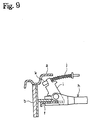
- a conventional dual mode drum brake device is explained with reference to Figures 8 and 9.
- Such a conventional device comprises a pair of brake shoes b, c which are mounted on a back plate a; a hydraulic cylinder e which is arranged between the upper side of the brake shoes b, c in order to pressurize the brake shoes b, c to be spread open with an anchor block d as the fulcrum; a pivot lever f which is pivotally superimposed under the left brake shoe b; a shoe clearance adjustment device g adjacent to the hydraulic cylinder e which is extended between both brake shoes b, c and functionally engages with the upper portion of the pivot lever f and the right brake shoe c; a strut h adjacent to the anchor block d, which is extended between both brake shoes b, c; and a brake lever i which engages with the lower portion of the pivot lever f and the left side of the strut h.
- the strut h spreads into two forked legs toward its left end.
- the brake lever i is pivotally mounted on one of forked legs at a back plate a side.
- a parking brake is designed to be activated by pulling a parking brake cable j connected with the end of the brake lever i.
- a through hole for the parking brake cable j needs to be formed near the anchor block d.
- this portion of the back plate needs to have the highest strength among other portions of the back plate a.
- securing the through hole possibly reduces the strength of the back plate a.
- Due to the decreased strength of the back plate a there is a need for a supplemental means to increase the strength of the back plate a, e.g., by adding a reinforcing plate or designing the back plate a to be thicker.
- adding the supplemental means and designing the back plate a to be thicker raise especially its weight and cost.
- the parking brake cable j is arranged at the lower portion of the back plate a. Hence, as the position where the parking brake cable j is arranged comes closer to the road surface, it becomes more likely to be damaged by being hit by flying gravel or by colliding with obstacles on the road surface.
- the entire brake lever i is to be located inside the brake device, and a cable end k of the parking brake cable j must be pre-connected with the brake lever i. These requirements make the connecting work more difficult and the handling of the brake device more inconvenient.
- This invention was made to improve the above points and to that end this invention provides a dual mode drum brake device which does not have a reduced strength of the back plate near the anchor block and which excludes the need of supplemental means to increase the strength of the back plate.
- Another aspect of this invention is to provide a dual mode drum brake device which enables to design the arrangement of the parking brake cable away from the road surface, thereby excluding the possibility of damaging the parking brake cable.
- Embodiment 1 of this invention is explained with reference to Figures 1-6.
- Figure 1 shows a plan view of a dual mode drum brake device, where a back plate 10 with its center hole 11 freely fitting over the wheel axle is fixed on the immovable part of the vehicle by bolts fastened at installation holes 12.
- a pair of brake shoes 20, 30 are designed to comprise shoe webs 21, 31 and shoe rims 22, 32, wherein the shoe web 21, 31 and the shoe rim 22, 32 are respectively connected to form a T-shape in the cross-section and linings 23, 33 are fixed on the shoe rims 22, 32.
- the two brake shoes 20, 30 are arranged to face each other and are held on the back plate 10 by shoe hold mechanisms 15 which can comprise for example the commonly known plate spring 13 and pin 14 arrangement.
- a service brake actuator 40 is provided between the facing upper ends of the shoe webs 21, 31 and is fixed on the upper portion of the back plate 10 by bolts.
- the service brake actuator 40 is a hydraulic type wheel brake cylinder and is arranged in that each of two built-in pistons 41 (the left side is omitted in the Figure) abuts against the upper end of the shoe web 21 and the upper end of the shoe web 31, respectively.
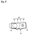
- An anchor block 50 is fixed at the other side of the service brake actuator 40. That is, the anchor block 50 is fixed at a lower portion of the back plate 10 so as to support the lower ends of the shoe webs 21, 31.
- the anchor block 50 is mounted on a protuberance 16 formed on the back plate 10 and comprises a rectangle supporting plate 51 supporting each lower end of the shoe webs 21, 31, a guiding plate 52 restricting the lifting the shoe webs 21, 31 off from the back plate 10, and rivets 53, 53 guided through and forged to connect the supporting plate 51 and the guiding plate 52 as well as the back plate 10 with each other.
- Members such as the guiding plate 52 and the rivet 53, which are the components of the anchor block 50, are not prerequisites for this invention.
- the purpose of this invention may be accomplished by integrally forming the supporting plate 51 and the guiding plate 52, welding these two members to the back plate 10, or by other solutions.
- Each lower end of two shoe webs 21, 31 may directly abut against the side surface of the supporting plate 51 to support the same. However, as illustrated in this embodiment, each lower end of the shoe webs 21, 31 may indirectly abut against the side surface of the supporting plate 51 with an elastic cushioning member 54 in between so as to elastically support the same.
- the cushioning member 54 may be formed by bending a plate spring in a C-shape shape or rectangular with one open side so as to be able to be attached to the circumference of the supporting plate 51.
- Left and right spring portions 55, 55 are integrally formed as the parts of the cushioning member 54, and the spring portions 55, 55 of the cushioning member 54 are elastically deformed upon the lower ends of the shoe webs 21, 31 pressing the supporting side surfaces of the supporting plate 51. Both spring portions 55, 55 absorb the impact force and suppress the impact noise, resulting from the collision between the lower ends of the shoe webs 21, 31 and the supporting plate 51.
- This drum brake device is equipped with a pivot lever 60 in order to function as a duo servo type (DS type) when a parking brake is applied.
- the pivot lever 60 is superimposed under the shoe web 21 of one brake shoe 20, and its central region pivotally mounts on the shoe web 21.
- Figure 4 shows an embodiment of a pivot structure in which a protuberance 61 integrally formed on the pivot lever 60 by pressing is smoothly movably fitted in a central hole 24 of the shoe web 21.
- the protuberance may be alterantively formed on the shoe web 21 side while the central hole may be formed on the pivot lever 60 side.
- a pivot structure with a combination of a pin (not shown in the Figure), a pivot lever, and a shoe web may be employed instead of the pivot structure of the above-explained protuberance 61 and the central hole 24.
- the upper end of the pivot lever 60 functionally engages with the parking brake actuator (comprising a later-described brake lever 90) while the lower end functionally engages with the left side of a strut 70 which extends between the other brake shoe 30 and the pivot lever 60.
- Return springs 17, 18 are stretched between the upper sides and between the lower sides of the brake shoes 20, 30. Portions near the upper ends of the shoe webs 21, 31 abut against a later described shoe clearance adjustment device 80. The lower ends of the shoe webs 21, 31 abut against the supporting surface of the anchor block 50.
- a mounting load of the shoe return springs 17, 18 is designed so that one adjacent facing ends of the brake shoes 20, 30 at the anchor block 50 side may not separate prior to the other adjacent facing ends thereof at the service brake actuator 40 side when activating a parking brake. Details of this shoe retraction spring arrangement are disclosed in the applicant's prior applications, e.g., the European Laid-Open Patent Publication Number EP 0800014 A2 and EP 0836027 A2, and the disclosures of which are incorporated by reference.
- FIGs 1 and 5 illustrate an example of an incremental type automatic shoe clearance adjustment device which is activated upon an application of a service brake.
- the automatic shoe clearance adjustment device 80 may comprise an extendible commonly known screw type strut (shoe clearance adjustment device) 81, an adjustment lever 82 pivotally supported on the left brake shoe 30, and an adjustment spring 83.
- the shoe clearance adjustment device 80 is arranged to be adjacent to the service brake actuator 40 and is extended between both shoe webs 21, 31.
- the strut 81 comprises an adjustment bolt 84, an adjustment nut 85, and an adjustment sleeve 86.
- Adjustment teeth 84a are integrally formed on the middle of the adjustment bolt 84.
- a male screw stem 84b at the right side of the adjustment bolt 84 is screwed into the adjustment nut 85 while the stem 84c at the left side rotatably fits into the adjustment sleeve 86.
- Outer ends of the above-described adjustment nut 85 and the adjustment sleeve 86 are formed as a plate shaped portion with notched grooves 85a, 86a.
- the stepped surface of the notched groove 85a on the right side of the adjustment nut 85 crosses and abuts against the bottom of the notched groove of the right shoe web 21 and the notched groove 85a holds the upper end of the pivot lever 60.
- the bottom of the notched groove 86a on the left side of the adjustment sleeve 86 crosses and abuts against the bottom of the notched groove of the left shoe web 31.
- a pivot portion 82a of the adjustment lever 82 is pivotally supported on the left shoe web 31 with the pin 87 as the fulcrum (see Figure 1).
- One arm 82b of the adjustment lever 82 abuts against a stepped surface 86b of the notched groove 86a on the adjustment sleeve 86 while the other arm 82c engages with the adjustment teeth 84a of the adjustment bolt 84 (see Figure 5).
- the adjustment spring 83 is stretched between the adjustment lever 82 and the left shoe web 31. In Figure 1, the adjustment spring 83 applies a clockwise acting force to the adjustment lever 82 with the pin 87 as the fulcrum.
- the strut 70 is a one shot type automatic stroke adjustment device and is arranged adjacent to the anchor block 50. If the strut 70 is explained with reference to Figures 1 and 6, it comprises an adjustment plate 71, a bell crank lever 72, and two springs 73, 74.
- a central region of the adjustment plate 71 has small teeth 71b.
- a central region of the bell crank lever 72 is pivotally supported at the left side of the adjustment plate 71 by a pin 75 piercing through an elongated hole of the adjustment plate 71. Because the pin 75 is located in the elongated hole with a longitudinal space, the central region of the bell crank lever 72 is movable in the longitudinal direction of the adjustment plate 71 along the plate surface.
- an elongated hole may be formed on the bell crank lever instead of on the adjustment plate surface.
- Small teeth 72b formed on a peripheral surface of a sector arm 72a at one side of the bell crank lever 72 engage with the small teeth 71b of the adjustment plate 71.
- another arm 72c with a cam surface freely fits into a substantially rectangular hole 35 formed on the left shoe web 31 with a clearance ⁇ 1 at its right side. There should be a small clearance at the left side of the rectangular hole 35, too, to avoid interference with associated parts due to manufacturing tolerances of each associated member.
- a clearance may be reserved between the upper strut 81 and the right shoe web 21.
- An anti-rattle spring 73 is stretched between the right shoe web 21 and the adjustment plate 71, and a quadrant spring 74 is stretched between the adjustment plate 71 and the pin 75.
- a mounting load of these springs 73, 74 is designed so that the mounting load of the anti-rattle spring 73 may be greater.
- the anti-rattle spring 73 applies an acting force via the strut 70 to the pivot lever 60 rotating counterclockwise with the pivot section relative to the shoe web 21.
- the anti-rattle spring 73 functions to prevent vibration of each member, i.e., the pivot lever 60, the strut 70 and the later described brake lever 90.
- a spring force of the anti-rattle spring 73 and the adjustment spring 83 toward the shoe clearance adjustment device, constituted by the strut 81, is designed so that the force of the adjustment spring 83 may be greater. This is because the strut 81 and the pivot lever 60 follow the opening of the right brake shoe 20 when the service brake is activated. At the same time, the strut 70 at the anchor block 50 side moves rightward in consort with the right brake shoe 20 with a spring force of the anti-rattle spring 73.
- a structural characteristic of this invention is in that the parking brake actuator is arranged at the service brake actuator 40 side.
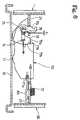
- a cross-pull type parking brake actuator which activates upon an activation of the parking brake, is disclosed in Figure 5.
- An almost L-shaped brake lever 90 is pivotally supported on the adjustment nut 85 with a pin 91.
- a finger-shaped operational portion 92 of the brake lever 90 slightly abuts against the upper inner circumferential surface of the pivot lever 60.
- Another arm 93 of the brake lever 90 is projected out from the brake assembly through a hole 19 formed in the back plate 10.
- a parking brake cable (not shown in the Figures) connected to a parking cable connecting hole 94 is to be pulled in the direction of A almost in a right angle relative to the back plate 10.
- an initial position of the brake lever 90 is restricted by a portion of the arm 93 abutting against the back plate 10.
- the hole 19 of the back plate 10 is designed to be located away from the anchor portion, where the section requires the greatest strength and also is designed to be located away from the road surface. Further, the parking brake cable may be connected after the drum brake device has been mounted on the vehicle.
- the other arm 93 of the brake lever 90 which is projecting out from the brake assembly, is pulled in the direction of A, i.e., almost in a right angle relative to the back plate 10.
- the brake lever 90 rotates clockwise with the pin 91 as the fulcrum, and the finger-shaped operational portion 92 pushes the upper inner circumferential surface of the pivot lever 60 outwardly.
- the pivot lever 60 rotates clockwise with the pivot point with the shoe web 21 as the fulcrum.
- the lower end of the pivot lever 60 is supported at the lower portion of the left brake shoe 30 via the strut 70, therefore, the acting force applied at the upper portion of the pivot lever 60 affects the pivot section with the shoe web 21.
- the spring force of both return springs 17 and 18 affecting the brake shoe 20 is designed so that the mounting load of the lower return spring 18 may be greater.
- the acting force is transmitted to the right shoe web 21 via the pivot section with the pivot lever 60.
- the right brake shoe 20 spreads open with the points of abutment against the anchor block 50 as the fulcrum, thereby pressing against the brake drum (not shown in the Figure).
- the pulling force of the brake lever 90 in Figure 5 is applied to the strut 81 at the service brake actuator 40 side via the pin 91, thereby shifting the strut 81 leftwards.
- the acting force via the strut 81 is transmitted to the left shoe web 31, and the left brake shoe 30 opens with the point of abutment against the anchor block 50 as the fulcrum, thereby pressing against the brake drum (not shown in Figure).
- both brake shoes 20, 30 have self-servo effects functioning as a highly effective DS type brake.
- the frictional force of the right brake shoe 20 is transmitted to the left brake shoe 30 via the strut 81. Accordingly, the lower end of the brake shoe 30 is supported by the anchor block 50, thereby functioning as a DS type brake as well.
- the spring portions 55, 55 of the cushioning material 54 covering the anchor block 50 absorb the impact force of the lower ends of the shoe webs 21, 31, thereby suppressing the impact noise.
- the spring force of the anti-rattle spring 73 is always being applied to the pivot lever 60 and the strut 70. Therefore, no vibration causing an impact noise is generated neither in braking nor in other states of operation, thereby eliminating the uncomfortable and unsecure feeling provided to the driver.
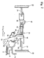
- Figure 7 shows a cross section of a different type of an embodiment of the parking brake lever characterized in that the direction of pulling the parking brake cable is different from the Embodiment 1.
- identical reference numbers are assigned to the same parts as in the Embodiment 1 and the explanations thereof are omitted.
- the brake lever 90 is an almost I shape, and the other arm 93 projects out from the brake through the hole 19 of the back plate 10. Further, a pair of brake shoes 20, 30 are designed to spread open by pulling the brake lever 90 almost parallel to the back plate 10.
- An extended portion 95 of the other arm 93 may abut against a supporting plate 9 arranged to be at the reverse side of the back plate 10, thereby restricting the initial position of the brake lever 90.
- a cable return spring 8 in the Figure 7 is stretched between the supporting plate 9 and the brake lever 90.
- the return spring 8 is not a prerequisite for this invention.
- a one shot type automatic shoe clearance adjustment device may be employed at the service brake actuator 40 side as well as at the anchor block 50 side.
- An incremental type or a one shot type may be applicable to an automatic shoe clearance adjustment device as well as an automatic stroke adjustment device.
- the brake lever 90, one component of the parking brake actuator may be arranged at the adjustment sleeve 86 side.
- this invention has the following advantages:
- a parking brake actuator which activates upon an activation of a parking brake, is arranged to be adjacent to a service brake actuator which activates upon an activation of a service brake actuator.
- the parking brake actuator is arranged to be adjacent to the service brake actuator.
- the parking brake cable may be arranged on the part of the back plate away from the road surface. This remarkably reduces the danger of damage to the parking brake cable by flying gravel.
- An operating portion of the parking brake lever is projected out from the brake. This facilitates the connecting work of the parking brake cable and assembly of the brake device.
- a cushioning member is arranged between the anchor block and the brake shoe. This suppresses the impact noise generated when the lower end of the brake shoe collides against the anchor block when releasing the parking brake.
- a resistance force against the opening of the brake shoe upon an application of the parking brake is designed to be greater at the anchor block side of the brake shoe than at the service brake actuator side of the brake shoe. This prevents the opening of the brake shoe at the anchor block side upon an activation of the parking brake prior to the opening of the brake shoe at the service brake actuator side. No impact noise is generated even if either one of the brake shoes rotates in consort with the brake drum, thereby avoiding an uncomfortable and unsecure feeling to the driver. Further, this invention gives an advantage for designing the strength near the anchor block since no impact load is generated, thereby eliminating the need of consideration of this effect.
- An incremental type or a one shot type is applicable to an automatic stroke adjustment device as well as an automatic shoe clearance adjustment device. This expands the scope of applicability and enables to commonly design the parts.
Landscapes
- Engineering & Computer Science (AREA)
- General Engineering & Computer Science (AREA)
- Mechanical Engineering (AREA)
- Braking Arrangements (AREA)
Abstract
Description
Another aspect of this invention is to provide a dual mode drum brake device which enables to design the arrangement of the parking brake cable away from the road surface, thereby excluding the possibility of damaging the parking brake cable.
Claims (8)
- A dual mode drum brake device, in which:a pair of brake shoes (20,30) are provided on a back plate (10) to face each other ;a service brake actuator (40) which is adapted to be activated upon an activation of a service brake is arranged between adjacent upper facing ends of said brake shoes (20, 30);an anchor block (50) is arranged between adjacent lower facing ends of said brake shoes (20,30);a pivot lever (60) is arranged such that a central region of said pivot lever (60) is pivotally mounted at a central region of one of the brake shoes (20,30);a shoe clearance adjustment device (80) is arranged adjacent to the service brake actuator (40) and extends between said pair of brake shoes (20,30) and functionally engages the upper portion of said pivot lever (60);a strut (70) is extended between the lower portion of said pivot lever (60) and the other one of said brake shoes (20,30) and functionally engages with the lower portion of said pivot lever (60); andsaid brake shoes (20,30) are designed to be able to spread open upon an activation of a parking brake, wherein:a parking brake actuator (90) which is adapted to activate upon the activation of said parking brake is arranged adjacent to the service brake actuator (40); andan operating portion (93) of said parking brake actuator (90) extends outside the brake through said back plate (10).
- A dual mode drum brake device as claimed in claim 1, wherein:said operating portion (93) of the parking brake actuator (90) which activates upon the activation of said parking brake is arranged to be movable in an almost right angle relative to said back plate (10).
- A dual mode drum brake device as claimed in claim 1, wherein:said operating portion (93) of the parking brake actuator (90) which activates upon the activation of said parking brake is arranged to be movable almost parallel to said back plate (10).
- A dual mode drum brake device as claimed in any of claims 1-3, wherein:a cushioning member (54,55) is arranged between said anchor block (50) and said brake shoes (20,30).
- A dual mode drum brake device as claimed in any of claims 1-4, wherein:a protuberance (61) is integrally formed by pressing on said central region of the pivot lever (60) or on said central region of said one of the brake shoes (20,30); andsaid protuberance (61) is pivotally supported in a hole (24) which is provided on either said pivot lever (60) or on said one of the brake shoes (20,30) which are not provided with said protuberance (61).
- A dual mode drum brake device as claimed in any of claims 1-5, wherein:when a central pivot section of said pivot lever (60) is a pivot point, a resistance force against the opening of said brake shoes (20,30) during a parking brake operation is designed to be larger (stronger) on an anchor block side of the brake shoes (20,30) than on a service brake actuator side of the brake shoes (20,30).
- A dual mode drum brake device as claimed in any of claims 1-6, wherein:said shoe clearance adjustment device (80) extended between said brake shoes (20,30) is adapted to automatically extend when sensing an excessive amount of opening of said pair of brake shoes (20,30) during a service brake operation and to adjust clearance between a brake drum and linings (23,33) of said brake shoes (20,30).
- A dual mode drum brake device as claimed in any of claim 1-7, wherein:said strut (70) extended between the lower portion of said pivot lever (60) and the lower portion of the other one of said brake shoes (20,30) is adapted to automatically extend when sensing an excessive amount of opening of said pair of brake shoes (20,30) and said pivot lever (60) during service brake operation and to adjust an application stroke of said parking brake actuator (90).
Applications Claiming Priority (2)
| Application Number | Priority Date | Filing Date | Title |
|---|---|---|---|
| JP4515999 | 1999-02-23 | ||
| JP04515999A JP3341155B2 (en) | 1999-02-23 | 1999-02-23 | Dual mode drum brake device |
Publications (3)
| Publication Number | Publication Date |
|---|---|
| EP1031753A2 true EP1031753A2 (en) | 2000-08-30 |
| EP1031753A3 EP1031753A3 (en) | 2003-11-26 |
| EP1031753B1 EP1031753B1 (en) | 2005-10-26 |
Family
ID=28922869
Family Applications (1)
| Application Number | Title | Priority Date | Filing Date |
|---|---|---|---|
| EP00100028A Expired - Lifetime EP1031753B1 (en) | 1999-02-23 | 2000-01-04 | A dual mode drum brake device |
Country Status (4)
| Country | Link |
|---|---|
| US (1) | US6390248B1 (en) |
| EP (1) | EP1031753B1 (en) |
| JP (1) | JP3341155B2 (en) |
| DE (1) | DE60023375D1 (en) |
Families Citing this family (5)
| Publication number | Priority date | Publication date | Assignee | Title |
|---|---|---|---|---|
| JP4540891B2 (en) | 2001-07-13 | 2010-09-08 | 豊生ブレーキ工業株式会社 | Parking brake |
| FR2839537B1 (en) * | 2002-05-07 | 2004-07-09 | Bosch Gmbh Robert | VEHICLE DRUM BRAKE AND ASSEMBLY METHOD THEREOF |
| KR100721369B1 (en) | 2003-03-18 | 2007-05-23 | 주식회사 만도 | Anchor block of drum brake apparatus |
| US7093695B1 (en) * | 2004-03-30 | 2006-08-22 | Kelsey-Hayes Company | Park brake cable end assembly for a drum-in-hat disc brake assembly |
| JP6114106B2 (en) * | 2012-07-25 | 2017-04-12 | 曙ブレーキ工業株式会社 | Drum brake device |
Citations (3)
| Publication number | Priority date | Publication date | Assignee | Title |
|---|---|---|---|---|
| US5070968A (en) | 1989-09-18 | 1991-12-10 | Kelsey-Hayes Company | Leading/trailing drum brake having servo parking brake |
| EP0800014A2 (en) | 1996-04-03 | 1997-10-08 | Nisshinbo Industries, Inc. | Drum type brake device |
| EP0836027A2 (en) | 1996-10-08 | 1998-04-15 | Nisshinbo Industries, Inc. | Drum brake device |
Family Cites Families (22)
| Publication number | Priority date | Publication date | Assignee | Title |
|---|---|---|---|---|
| GB990758A (en) * | 1963-01-17 | 1965-04-28 | Automotive Prod Co Ltd | Improvements in and relating to automatic adjusting devices for internal expanding shoe drum brakes |
| US3323618A (en) * | 1965-09-21 | 1967-06-06 | Girling Ltd | Automatic adjuster for vehicle brakes |
| GB1198362A (en) * | 1968-01-15 | 1970-07-15 | Automotive Prod Co Ltd | Improvements in or relating to Automatic Adjusting Means for Internal Shoe Drum Brakes |
| GB1360974A (en) * | 1970-08-24 | 1974-07-24 | Girling Ltd | Internal shoe drum brakes |
| GB1405094A (en) * | 1971-09-23 | 1975-09-03 | Girling Ltd | Internal shoe-drum brakes |
| GB1410514A (en) * | 1972-10-06 | 1975-10-15 | Girling Ltd | Internal shoe drum brakes |
| JPS5247173A (en) * | 1975-10-13 | 1977-04-14 | Nissan Motor Co Ltd | Shoe clearance automatic adjuster in drum brake |
| JPS589296B2 (en) * | 1976-09-09 | 1983-02-19 | 日産自動車株式会社 | Automatic shoe clearance adjustment device for internally expanding drum brakes |
| NL7900653A (en) * | 1978-02-01 | 1979-08-03 | Girling Ltd | DRUM BRAKE. |
| JPS5733233A (en) * | 1980-07-31 | 1982-02-23 | Toyota Motor Corp | Parking brake mechanism in internal expanding hydraulic oil brake system |
| US4480726A (en) * | 1980-11-20 | 1984-11-06 | Nisshin Kogyo Kabushiki Kaisha | Arrangement for automatic adjustment of braking gaps in drum brakes |
| GB8720203D0 (en) * | 1987-08-27 | 1987-10-07 | Lucas Ind Plc | Brake actuator |
| GB8817007D0 (en) * | 1988-07-16 | 1988-08-17 | Bba Group Plc | Drum brake assembly |
| US5058713A (en) * | 1989-07-31 | 1991-10-22 | Kelsey-Hayes Company | Hydraulic drum brake assembly |
| US5275260A (en) * | 1989-09-18 | 1994-01-04 | Kelsey-Hayes Company | Dual mode drum brake assembly |
| US5193653A (en) * | 1990-08-23 | 1993-03-16 | Allied-Signal Inc. | Mechanically actuated brake with automatic adjustment |
| US5538112A (en) * | 1994-10-11 | 1996-07-23 | Kelsey-Hayes Company | Parking and emergancy brake actuating lever for drum brake assembly |
| US5720367A (en) * | 1995-08-23 | 1998-02-24 | Kelsey-Hayes Company | Parking and emergency brake operating mechanism for dual mode drum brake assemlby |
| US5924529A (en) * | 1996-04-05 | 1999-07-20 | Nisshinbo Industries, Inc. | Drum brake device with single shoe extension device |
| JP3338946B2 (en) * | 1996-10-08 | 2002-10-28 | 日清紡績株式会社 | Drum brake device |
| JP3343715B2 (en) * | 1996-11-13 | 2002-11-11 | 日清紡績株式会社 | Drum brake device |
| JP3341147B2 (en) * | 1997-10-13 | 2002-11-05 | 日清紡績株式会社 | Drum brake device |
-
1999
- 1999-02-23 JP JP04515999A patent/JP3341155B2/en not_active Expired - Fee Related
-
2000
- 2000-01-04 EP EP00100028A patent/EP1031753B1/en not_active Expired - Lifetime
- 2000-01-04 DE DE60023375T patent/DE60023375D1/en not_active Expired - Lifetime
- 2000-02-17 US US09/506,029 patent/US6390248B1/en not_active Expired - Fee Related
Patent Citations (3)
| Publication number | Priority date | Publication date | Assignee | Title |
|---|---|---|---|---|
| US5070968A (en) | 1989-09-18 | 1991-12-10 | Kelsey-Hayes Company | Leading/trailing drum brake having servo parking brake |
| EP0800014A2 (en) | 1996-04-03 | 1997-10-08 | Nisshinbo Industries, Inc. | Drum type brake device |
| EP0836027A2 (en) | 1996-10-08 | 1998-04-15 | Nisshinbo Industries, Inc. | Drum brake device |
Also Published As
| Publication number | Publication date |
|---|---|
| DE60023375D1 (en) | 2005-12-01 |
| EP1031753A3 (en) | 2003-11-26 |
| JP2000240698A (en) | 2000-09-05 |
| JP3341155B2 (en) | 2002-11-05 |
| US6390248B1 (en) | 2002-05-21 |
| EP1031753B1 (en) | 2005-10-26 |
Similar Documents
| Publication | Publication Date | Title |
|---|---|---|
| US5070968A (en) | Leading/trailing drum brake having servo parking brake | |
| US8556045B2 (en) | Drum-in-hat disc brake assembly | |
| KR100493583B1 (en) | Drum brake device | |
| US5630486A (en) | Mechanical actuation device for drum brake | |
| JP3728574B2 (en) | Automatic brake clearance adjustment device for drum brakes | |
| EP1031753B1 (en) | A dual mode drum brake device | |
| US6374965B1 (en) | Damped brake shoe support device for drum brake assembly | |
| US5538112A (en) | Parking and emergancy brake actuating lever for drum brake assembly | |
| JP3341150B2 (en) | Drum brake device | |
| US20030150676A1 (en) | Dual mode type drum brake device | |
| US6325183B2 (en) | Brake cable mounting structure for a drum brake | |
| US7490702B1 (en) | Parking and emergency brake actuator for a drum-in-hat disc brake assembly | |
| KR100435197B1 (en) | Drum brake | |
| US20050145451A1 (en) | Adapter for vehicle brake assembly | |
| JP2003269498A (en) | Dual mode drum brake device | |
| US6554110B2 (en) | Drum brake device | |
| JPH0710108Y2 (en) | Drum brake | |
| JPH0710110Y2 (en) | Drum brake | |
| KR200281976Y1 (en) | Drum brake operating lever | |
| JPH0710112Y2 (en) | Drum brake | |
| JPH0710111Y2 (en) | Drum brake | |
| US6581735B2 (en) | Drum brake device | |
| US6547047B2 (en) | Drum brake device | |
| JPS5833312Y2 (en) | Automatic gap adjustment device for drum brake equipment | |
| JP4597345B2 (en) | Drum brake |
Legal Events
| Date | Code | Title | Description |
|---|---|---|---|
| PUAI | Public reference made under article 153(3) epc to a published international application that has entered the european phase |
Free format text: ORIGINAL CODE: 0009012 |
|
| AK | Designated contracting states |
Kind code of ref document: A2 Designated state(s): AT BE CH CY DE DK ES FI FR GB GR IE IT LI LU MC NL PT SE |
|
| AX | Request for extension of the european patent |
Free format text: AL;LT;LV;MK;RO;SI |
|
| PUAL | Search report despatched |
Free format text: ORIGINAL CODE: 0009013 |
|
| AK | Designated contracting states |
Kind code of ref document: A3 Designated state(s): AT BE CH CY DE DK ES FI FR GB GR IE IT LI LU MC NL PT SE |
|
| AX | Request for extension of the european patent |
Extension state: AL LT LV MK RO SI |
|
| RIC1 | Information provided on ipc code assigned before grant |
Ipc: 7F 16D 65/22 A |
|
| 17P | Request for examination filed |
Effective date: 20040517 |
|
| AKX | Designation fees paid |
Designated state(s): DE FR |
|
| 17Q | First examination report despatched |
Effective date: 20040810 |
|
| GRAP | Despatch of communication of intention to grant a patent |
Free format text: ORIGINAL CODE: EPIDOSNIGR1 |
|
| GRAS | Grant fee paid |
Free format text: ORIGINAL CODE: EPIDOSNIGR3 |
|
| GRAA | (expected) grant |
Free format text: ORIGINAL CODE: 0009210 |
|
| AK | Designated contracting states |
Kind code of ref document: B1 Designated state(s): DE FR |
|
| REF | Corresponds to: |
Ref document number: 60023375 Country of ref document: DE Date of ref document: 20051201 Kind code of ref document: P |
|
| PG25 | Lapsed in a contracting state [announced via postgrant information from national office to epo] |
Ref country code: DE Free format text: LAPSE BECAUSE OF FAILURE TO SUBMIT A TRANSLATION OF THE DESCRIPTION OR TO PAY THE FEE WITHIN THE PRESCRIBED TIME-LIMIT Effective date: 20060127 |
|
| ET | Fr: translation filed | ||
| PLBE | No opposition filed within time limit |
Free format text: ORIGINAL CODE: 0009261 |
|
| STAA | Information on the status of an ep patent application or granted ep patent |
Free format text: STATUS: NO OPPOSITION FILED WITHIN TIME LIMIT |
|
| 26N | No opposition filed |
Effective date: 20060727 |
|
| PGFP | Annual fee paid to national office [announced via postgrant information from national office to epo] |
Ref country code: FR Payment date: 20080108 Year of fee payment: 9 |
|
| REG | Reference to a national code |
Ref country code: FR Ref legal event code: ST Effective date: 20091030 |
|
| PG25 | Lapsed in a contracting state [announced via postgrant information from national office to epo] |
Ref country code: FR Free format text: LAPSE BECAUSE OF NON-PAYMENT OF DUE FEES Effective date: 20090202 |