EP1031683A1 - Vehicle door handle - Google Patents
Vehicle door handle Download PDFInfo
- Publication number
- EP1031683A1 EP1031683A1 EP00103644A EP00103644A EP1031683A1 EP 1031683 A1 EP1031683 A1 EP 1031683A1 EP 00103644 A EP00103644 A EP 00103644A EP 00103644 A EP00103644 A EP 00103644A EP 1031683 A1 EP1031683 A1 EP 1031683A1
- Authority
- EP
- European Patent Office
- Prior art keywords
- handle
- connecting member
- door
- seat
- lever
- Prior art date
- Legal status (The legal status is an assumption and is not a legal conclusion. Google has not performed a legal analysis and makes no representation as to the accuracy of the status listed.)
- Granted
Links
Images

Classifications
-
- E—FIXED CONSTRUCTIONS
- E05—LOCKS; KEYS; WINDOW OR DOOR FITTINGS; SAFES
- E05B—LOCKS; ACCESSORIES THEREFOR; HANDCUFFS
- E05B79/00—Mounting or connecting vehicle locks or parts thereof
- E05B79/02—Mounting of vehicle locks or parts thereof
- E05B79/06—Mounting of handles, e.g. to the wing or to the lock
-
- E—FIXED CONSTRUCTIONS
- E05—LOCKS; KEYS; WINDOW OR DOOR FITTINGS; SAFES
- E05B—LOCKS; ACCESSORIES THEREFOR; HANDCUFFS
- E05B81/00—Power-actuated vehicle locks
- E05B81/54—Electrical circuits
- E05B81/64—Monitoring or sensing, e.g. by using switches or sensors
- E05B81/76—Detection of handle operation; Detection of a user approaching a handle; Electrical switching actions performed by door handles
- E05B81/78—Detection of handle operation; Detection of a user approaching a handle; Electrical switching actions performed by door handles as part of a hands-free locking or unlocking operation
-
- E—FIXED CONSTRUCTIONS
- E05—LOCKS; KEYS; WINDOW OR DOOR FITTINGS; SAFES
- E05B—LOCKS; ACCESSORIES THEREFOR; HANDCUFFS
- E05B85/00—Details of vehicle locks not provided for in groups E05B77/00 - E05B83/00
- E05B85/10—Handles
- E05B85/14—Handles pivoted about an axis parallel to the wing
- E05B85/16—Handles pivoted about an axis parallel to the wing a longitudinal grip part being pivoted at one end about an axis perpendicular to the longitudinal axis of the grip part
Definitions
- the present invention relates to a vehicle door handle.
- the present invention relates to a handle of the type comprising a connecting structure fitted to the vehicle door; a lever hinged to the connecting structure and activated, in use, by a user to control a lock on the door; and a user presence detecting device comprising an aerial housed inside the lever to detect the presence of the user about to open the door, and to emit a relative alert signal.
- a handle for a vehicle door comprising a connecting element which is fitted integrally to said door; a movable control element connected to said connecting element and activated manually by a user to control, in use, a lock on said door; and user presence detecting means carried by said movable control element and in turn comprising an output cable, a first electric connecting member connected to said output cable, and a second electric connecting member connected to said first connecting member and which is connected to a cable on said door; characterized in that at least one of said connecting members is connected to one of said elements.
- Number 1 in Figure 1 indicates a handle (shown partly) fitted to a vehicle door 2, which has an outer body 3 having an opening 4.
- handle 1 comprises a connecting structure 5 connected integrally, in known manner not described in detail, to an inner frame (not shown) of door 2 and having a cavity 6.
- Cavity 6 is defined by an end wall 7 having an opening 8; by two lateral portions 9 and 10, portion 9 being located adjacent to body 3, and portion 10 being located on the opposite side of portion 9 to body 3; and by two lateral walls 11 facing each other and extending between portions 9 and 10.
- Handle 1 also comprises a movable control lever 13 extending in a longitudinal direction and facing body 3; and a seal 15 interposed between lever 13 and body 3 and closing opening 4.
- Lever 13 comprises a hollow body 17, which is gripped, in use, by the user's hand to open a lock (not shown) on door 2; and an end arm 19, which extends integrally from body 17 through opening 4, is surrounded by seal 15, and is hinged, in known manner not described in detail, to structure 5 to permit rotation of lever 13 about a hinge axis 20 perpendicular to the longitudinal direction and parallel to body 3.
- handle 1 also comprises a detecting device 21 for detecting the presence of the user about to open door 2.
- Device 21 comprises an aerial 23 housed inside body 17; an output cable 25 extending through opening 4; and an electric connector 27 for connecting cable 25 to a cable 29 on door 2, extending through opening 8 to transmit an alert signal emitted by aerial 23.
- Electric connector 27 is located on the opposite side of arm 19 to body 3, and comprises a first and a second element 30 and 31 connected to each other in a longitudinal connection direction.
- Element 30 is connected to cable 25 and comprises an outer casing 34 formed in one piece with arm 19; and element 31 is connected to cable 29, is housed partially inside cavity 6, and is connected to structure 5 by means of a click-on connecting assembly 37 interposed between element 31 and structure 5.
- assembly 37 comprises a retaining seat 39 formed in portion 9 inside cavity 6; an outer tooth 41 carried by element 31 and engaging seat 39 loosely to allow element 31 to move with respect to structure 5; and a metal leaf spring 43.
- Spring 43 is U-shaped, is connected integrally to portion 10, and extends inside cavity 6 to exert elastic action on element 31 towards seat 39, so as to retain tooth 41 inside seat 39 and enable element 31, guided by lateral walls 11, to move with respect to structure 5 in a plane perpendicular to axis 20.
- element 30 is connected integrally to lever 13 by means of a respective click-on connecting assembly 47 interposed between element 30 and arm 19, and comprising a dove-tail seat 53 formed longitudinally in casing 34 and defined by a transverse bottom surface 54, a guide portion 55 for guiding arm 19 and engaging seat 53, and a retaining device 56 for retaining portion 55 resting on bottom surface 54.
- a respective click-on connecting assembly 47 interposed between element 30 and arm 19, and comprising a dove-tail seat 53 formed longitudinally in casing 34 and defined by a transverse bottom surface 54, a guide portion 55 for guiding arm 19 and engaging seat 53, and a retaining device 56 for retaining portion 55 resting on bottom surface 54.
- Device 56 comprises a hemispherical cavity formed in portion 55, positioned facing casing 34, and inside which clicks a hemispherical elastic appendix integral with casing 34.
- device 56 comprises an elastic tab integral with casing 34 and located on the opposite side with respect to bottom surface 54 to click past portion 55.
- lever 13 When assembling handle 1, once structure 5 is connected to door 2, lever 13 is connected to structure 5 by tilting lever 13 with respect to body 3 and inserting arm 19 and element 30, integral with each other, through opening 4. Elements 30 and 31 may be connected to each other before connecting arm 19 to structure 5, in which case, cable 29 is simply slid through opening 8, and lever 13 pushed to click electric connector 27 inside cavity 6. Alternatively, element 31 is clicked inside cavity 6, and elements 30 and 31 are connected to each other when hinging arm 19 to structure 5.
- electric connector 27 of handle 1 rotates, integrally with lever 13, between a rest position (shown by the continuous line in Figure 1) and a lock control position (shown by the dash line in Figure 1) tilted with respect to the rest position, and in which tooth 41 still engages seat 39.
- lever 13 is used to rotate electric connector 27 past the control position to release tooth 41 from seat 39 and withdraw arm 19 from door 2.
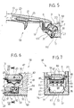
- FIG. 5 The embodiment shown in Figures 5, 6 and 7 relates to a handle 58, portions 9 and 10 and walls 7 and 11 of which define a fixed body 59 for connecting and housing arm 19, which extends inside cavity 6 in a longitudinal direction and is hinged to lateral walls 11 to rotate about axis 20.
- Handle 58 also comprises a seal 60 surrounding arm 19 and closing cavity 6.
- electric connector 27 comprises a first and a second connecting element 61 and 62, which in turn comprise respective sets of three contacts 63 and 64 connected to each other in sliding manner, and respective supporting bases 65 and 66.
- Bases 65 and 66 are co-molded with respective contacts 63 and 64, and are connected integrally in fixed positions to arm 19 and portion 10 respectively by means of respective click-on connecting assemblies 47 and 37.
- assembly 37 comprises a seat 67 formed in portion 10, facing arm 19, and defined longitudinally by an end surface 69; an elastic tab 71 formed in one piece with portion 10 inside seat 67 and spaced apart from end surface 69 to click base 66 against end surface 69; and two longitudinal locating grooves 72 differing in size and formed opposite each other inside the seat.
- Base 66 is defined by a hollow parallelepiped-shaped body, which is locked between tab 71 and end surface 69 and has two outer locating ribs 76 differing in size and extending longitudinally along opposite lateral faces to engage respective grooves 72.
- base 66 partly houses contacts 64, each of which is connected to cable 29 and extends through base 66, perpendicularly to axis 20 and portion 10, towards a respective contact 63.
- Base 66 also houses a set of three springs 80, each of which pushes a respective contact 64 towards axis 20 to keep contacts 63 and 64 in contact with each other.
- connecting assembly 47 comprises a seat 81 defined by two transverse shoulders 83 spaced apart from each other and between which platelike base 65 is interposed facing base 66.
- Assembly 47 also comprises a click-on retaining device defined by two longitudinal ribs 84 extending integrally from arm 19 towards respective walls 11, and by two elastic longitudinal appendixes 85 carried laterally by base 65 and extending towards axis 20 to engage ribs 84.
- Base 65 houses three contacts 63 defined by respective elastically deformable blades, each of which is connected to cable 25 and is bridge-shaped so as to contact respective contact 64 at a point lying along a line perpendicular to axis 20 and portion 10.
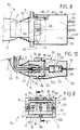
- FIG. 8 The embodiment shown in Figures 8, 9 and 10 relates to a handle 90, the electric connector 27 of which, unlike handle 58, comprises three annular contacts 91 comolded into arm 19 housed inside cavity 6; and a connecting element 92.
- Contacts 91 are connected to cable 25, have respective longitudinal axes 93 extending in a plane parallel to axis 20, and communicate with cavity 6.
- Element 92 is located on the opposite side of end wall 7 to arm 19, is detached from wall 7, and comprises three inner guides 95 coaxial with axes 93, and a front end collar 96.
- Collar 96 loosely houses part of body 59, and is hinged to walls 11 by means of click-on connecting assembly 37, which comprises two pins hinging body 59 and engaging respective seats formed in collar 96 to rotate about a respective hinge axis coincident with axis 20.
- Assembly 37 also comprises three longitudinal locating grooves 98 formed in collar 96, two facing portion 9 and one facing portion 10; and three locating pins 99, each integral with body 59 and loosely engaging a respective groove 98.
- element 92 houses a set of three contacts 100, each of which is connected to cable 29, slides inside a respective guide 95 along a respective axis 93, and extends outside element 92 and loosely through a respective opening 8 in wall 7 to engage a respective contact 91.
- element 92 comprises a seal 103 interposed between element 92 and end wall 7 and about contacts 100; and a set of three springs 104, each of which is housed inside a respective guide 95 to axially push respective contact 100 towards arm 19 and prevent damage to electric connector 27 when connecting contacts 91 and 100.
- element 92 rotates, together with arm 19 and hence with contacts 91, about axis 20 and with respect to body 59 by virtue of the clearance, in a plane perpendicular to axis 20, between body 59 and element 92.
- Fitting at least one of the connecting elements of electric connector 27 to lever 13 or to structure 5 therefore provides the fitter with a fixed reference by which to connect the connecting elements quickly and easily, thus enabling handles 1, 58 and 90 to be fitted to door 2 relatively quickly and cheaply.
- the two connecting elements can be connected when connecting lever 13 to structure 5, with no need to work directly on connector 27, thus further reducing assembly time and cost as compared with known solutions.
- Simplifying assembly also greatly reduces the risk of the two connecting elements being connected improperly, thus reducing the risk of the elements working loose, and so improving, as compared with known solutions, the reliability and efficiency of handles 1, 58 and 90, and in particular of the electric connection of aerial 23 and, hence, electric control of the lock of door 2.
- connector 27 generates very little noise.
- aerial 23 and cable 25 may be comolded with lever 13; elements 61 and 62 of handle 58 may be co-molded with lever 13 and body 59 respectively; the type of electric connector and the assemblies connecting the connecting elements to lever 13 and to structure 5 may be other than as described by way of example; and/or the lever may be connected to structure 5 differently from the manner described.
Landscapes
- Lock And Its Accessories (AREA)
Abstract
Description
Claims (13)
- A handle (1; 58; 90) for a vehicle door (2), the handle comprising a connecting element (5) which is fitted integrally to said door (2); a movable control element (13) connected to said connecting element (5) and activated manually by a user to control, in use, a lock on said door (2); and user presence detecting means (21) carried by said movable control element (13) and in turn comprising an output cable (25), a first electric connecting member (30; 61; 91) connected to said output cable (25), and a second electric connecting member (31; 62; 92) connected to said first connecting member (30; 61; 91) and which is connected to a cable (29) on said door (2); characterized in that at least one of said connecting members (30; 61; 91) (31; 62; 92) is connected to one of said elements (13) (5).
- A handle as claimed in Claim 1, characterized in that said first (30; 61; 91) and said second (31; 62; 92) connecting member are connected to said movable control element (13) and said connecting element (5) respectively.
- A handle as claimed in Claim 1 or 2, characterized in that at least one of said connecting members (30; 61; 91) (62) is connected integrally to the relative said element (14 ((5).
- A handle as claimed in Claim 3, characterized in that said first connecting member (91) is co-molded with said movable control element (13).
- A handle as claimed in Claim 3, characterized in that said first connecting member (30) comprises an outer casing (34) formed in one piece with said movable control element (13).
- A handle as claimed in one of Claims 1 to 5, characterized by comprising click-on connecting means (47) (37) interposed between at least one of said connecting members (30; 61) (31; 62; 92) and the relative said element (13) (5).
- A handle as claimed in Claim 6, characterized in that said click-on connecting means (37) comprise a seat (39) formed in said connecting element (5); and a tooth (41) carried by said second connecting member (31) and loosely engaging said seat (39); elastic means (43) being provided to keep said tooth (41) engaged inside said seat (39) to permit displacement of said second connecting member (31) with respect to said connecting element (5).
- A handle as claimed in Claim 7, characterized in that said connecting element (5) defines a cavity (6) loosely housing at least part of said second connecting member (31) and said elastic means (43); said seat (39) being formed in said cavity (6).
- A handle as claimed in one of Claims 1 to 6, characterized in that both said connecting members (61) (62) are connected to the respective said elements (13) (5) in fixed positions with respect to the respective elements (13) (5), and comprise respective contacts (63) (64) connected to one another in sliding manner.
- A handle as claimed in Claim 9, characterized in that said contacts (63) of one of said connecting members (61) are defined by elastically deformable blades.
- A handle as claimed in one of Claims 1 to 6, characterized in that said connecting element (5) comprises a connecting portion (59), and said second connecting member (92) is hinged to the connecting portion (59) to rotate, together with said first connecting member (91), about a respective hinge axis.
- A handle as claimed in Claim 11, characterized in that said movable control element (13) is hinged to said connecting element (5) to rotate about an axis (20) coincident with said hinge axis.
- A handle as claimed in Claim 11 or 12, characterized in that said connecting portion (59) comprises a further cavity (6) housing said first connecting member (91); and in that said second connecting member (92) comprises a tubular portion (96) loosely housing at least part of said connecting portion (59), and respective contacts (100) extending loosely through the connecting portion (59) and engaging said first connecting member (91).
Priority Applications (1)
| Application Number | Priority Date | Filing Date | Title |
|---|---|---|---|
| DE60020179.1T DE60020179T3 (en) | 1999-02-23 | 2000-02-21 | door handle for motor vehicles |
Applications Claiming Priority (2)
| Application Number | Priority Date | Filing Date | Title |
|---|---|---|---|
| IT1999TO000141A IT1308388B1 (en) | 1999-02-23 | 1999-02-23 | HANDLE FOR A VEHICLE DOOR. |
| ITTO990141 | 1999-02-23 |
Publications (3)
| Publication Number | Publication Date |
|---|---|
| EP1031683A1 true EP1031683A1 (en) | 2000-08-30 |
| EP1031683B1 EP1031683B1 (en) | 2005-05-18 |
| EP1031683B2 EP1031683B2 (en) | 2022-12-21 |
Family
ID=11417520
Family Applications (1)
| Application Number | Title | Priority Date | Filing Date |
|---|---|---|---|
| EP00103644.1A Expired - Lifetime EP1031683B2 (en) | 1999-02-23 | 2000-02-21 | Vehicle door handle |
Country Status (3)
| Country | Link |
|---|---|
| EP (1) | EP1031683B2 (en) |
| DE (1) | DE60020179T3 (en) |
| IT (1) | IT1308388B1 (en) |
Cited By (14)
| Publication number | Priority date | Publication date | Assignee | Title |
|---|---|---|---|---|
| EP1108835A3 (en) * | 1999-12-17 | 2003-01-15 | Robert Bosch Gmbh | Outside door handle for motor vehicle door, a motor vehicle door, and method of mounting an outside door handle |
| EP1291480A1 (en) * | 2001-08-16 | 2003-03-12 | Valeo Sicurezza Abitacolo S.p.A. | Outside vehicle handle |
| EP1306503A1 (en) * | 2001-10-24 | 2003-05-02 | Huf Hülsbeck & Fürst GmbH & Co. KG | Device for operating a lock of doors or wings, in particular on vehicles |
| EP1255004A3 (en) * | 2001-05-02 | 2004-02-04 | Kiekert Aktiengesellschaft | Door handle unit |
| JP2005082091A (en) * | 2003-09-10 | 2005-03-31 | Tyco Electronics Amp Kk | Connector holding structure |
| EP1447498A3 (en) * | 2003-02-15 | 2007-03-21 | Kiekert Aktiengesellschaft | Door handle device for a vehicle door |
| EP1445401A3 (en) * | 2003-01-29 | 2007-03-28 | Aisin Seiki Kabushiki Kaisha | Outside handle apparatus and connector mechanism |
| EP1839958A1 (en) * | 2006-03-29 | 2007-10-03 | Sumitomo Wiring Systems, Ltd. | A connector connecting construction, a clamping member and a method of mounting a connector connecting construction |
| EP1548212A3 (en) * | 2003-12-22 | 2008-08-20 | Aisin Seiki Kabushiki Kaisha | Handle device |
| CN1985060B (en) * | 2004-07-10 | 2011-06-15 | 胡夫休尔斯贝克及福尔斯特公司 | Device for actuating a lock integrated in a door, hatch, or similar, especially in a vehicle |
| WO2012116793A1 (en) * | 2011-03-01 | 2012-09-07 | Brose Fahrzeugteile Gmbh & Co. Kg, Hallstadt | Door handle unit for a vehicle |
| EP1284335B2 (en) † | 2001-08-16 | 2015-05-27 | U-Shin Italia S.p.A. | Door handle incorporating an electronic module, in particular for a vehicle |
| DE102009043933B4 (en) | 2009-09-02 | 2019-08-14 | Witte-Velbert Gmbh & Co. Kg | An automobile door handle |
| CN116641608A (en) * | 2022-02-24 | 2023-08-25 | 法拉利股份有限公司 | Handle for operating an automatic moving mechanism of a door of a motor vehicle |
Families Citing this family (3)
| Publication number | Priority date | Publication date | Assignee | Title |
|---|---|---|---|---|
| DE102006021120B9 (en) | 2006-05-04 | 2018-09-06 | Huf Hülsbeck & Fürst Gmbh & Co. Kg | actuator |
| DE102009020247B4 (en) | 2009-05-07 | 2021-09-09 | Huf Hülsbeck & Fürst Gmbh & Co. Kg | Actuating device for a flap of a motor vehicle |
| DE102013112164A1 (en) | 2013-11-05 | 2015-05-21 | Huf Hülsbeck & Fürst Gmbh & Co. Kg | Automotive exterior handle |
Citations (2)
| Publication number | Priority date | Publication date | Assignee | Title |
|---|---|---|---|---|
| DE4212291A1 (en) * | 1992-04-11 | 1993-10-14 | Daimler Benz Ag | Arrangement of a switching element that can be influenced without contact |
| DE19633894A1 (en) * | 1996-08-22 | 1998-02-26 | Huf Huelsbeck & Fuerst Gmbh | Exterior car door handle for door lock |
Family Cites Families (12)
| Publication number | Priority date | Publication date | Assignee | Title |
|---|---|---|---|---|
| CH154388A (en) † | 1929-05-08 | 1932-04-30 | Eckert Eugen Von | Stop display device. |
| US3989343A (en) † | 1976-01-27 | 1976-11-02 | Amp Incorporated | Means for mounting an electrical connector in a panel opening from either side of the panel |
| DE3628376A1 (en) † | 1986-08-21 | 1988-02-25 | Daimler Benz Ag | Door-handle arrangement for doors of motor vehicles |
| DE3634695A1 (en) † | 1986-10-11 | 1988-04-21 | Reinshagen Kabelwerk Gmbh | Multipole lockable electrical plug connection |
| DE3819104A1 (en) † | 1988-06-04 | 1989-12-07 | Opel Adam Ag | MOTOR VEHICLE WITH A CENTER CONSOLE WITH A SWITCH AND / OR ELECTRICAL DISPLAY DEVICES |
| GB2253435A (en) † | 1991-03-02 | 1992-09-09 | Ford Motor Co | Latch module for a vehicle door |
| DE19507911B4 (en) † | 1995-03-07 | 2004-04-29 | Kiekert Ag | Actuator for the door lock of a motor vehicle door |
| DE19539496A1 (en) † | 1995-10-24 | 1997-04-30 | Bayerische Motoren Werke Ag | Bundled cables or pipes fixing unit e.g. for motor vehicle |
| DE19653513B4 (en) † | 1995-12-23 | 2004-04-29 | Volkswagen Ag | Mounting Clip System |
| DE19606643C2 (en) † | 1996-02-22 | 2003-11-20 | Itw Ateco Gmbh | Fastening device for cable harnesses and use of the fastening device |
| DE19619978C2 (en) † | 1996-05-17 | 1999-04-08 | Delphi Automotive Systems Gmbh | Device for coupling or uncoupling at least one plug connection in a place that is difficult to access, in particular on the seat frame in a vehicle |
| DE19647021A1 (en) † | 1996-11-14 | 1998-05-20 | Teves Gmbh Alfred | Connector with a plug, an intermediate part and a housing |
-
1999
- 1999-02-23 IT IT1999TO000141A patent/IT1308388B1/en active
-
2000
- 2000-02-21 DE DE60020179.1T patent/DE60020179T3/en not_active Expired - Lifetime
- 2000-02-21 EP EP00103644.1A patent/EP1031683B2/en not_active Expired - Lifetime
Patent Citations (2)
| Publication number | Priority date | Publication date | Assignee | Title |
|---|---|---|---|---|
| DE4212291A1 (en) * | 1992-04-11 | 1993-10-14 | Daimler Benz Ag | Arrangement of a switching element that can be influenced without contact |
| DE19633894A1 (en) * | 1996-08-22 | 1998-02-26 | Huf Huelsbeck & Fuerst Gmbh | Exterior car door handle for door lock |
Cited By (17)
| Publication number | Priority date | Publication date | Assignee | Title |
|---|---|---|---|---|
| EP1108835A3 (en) * | 1999-12-17 | 2003-01-15 | Robert Bosch Gmbh | Outside door handle for motor vehicle door, a motor vehicle door, and method of mounting an outside door handle |
| EP1255004A3 (en) * | 2001-05-02 | 2004-02-04 | Kiekert Aktiengesellschaft | Door handle unit |
| EP1291480A1 (en) * | 2001-08-16 | 2003-03-12 | Valeo Sicurezza Abitacolo S.p.A. | Outside vehicle handle |
| EP1284335B2 (en) † | 2001-08-16 | 2015-05-27 | U-Shin Italia S.p.A. | Door handle incorporating an electronic module, in particular for a vehicle |
| EP1306503A1 (en) * | 2001-10-24 | 2003-05-02 | Huf Hülsbeck & Fürst GmbH & Co. KG | Device for operating a lock of doors or wings, in particular on vehicles |
| EP1445401A3 (en) * | 2003-01-29 | 2007-03-28 | Aisin Seiki Kabushiki Kaisha | Outside handle apparatus and connector mechanism |
| EP1447498A3 (en) * | 2003-02-15 | 2007-03-21 | Kiekert Aktiengesellschaft | Door handle device for a vehicle door |
| US7402043B2 (en) | 2003-09-10 | 2008-07-22 | Tyco Electronics Amp K.K. | Connector holder structure |
| JP2005082091A (en) * | 2003-09-10 | 2005-03-31 | Tyco Electronics Amp Kk | Connector holding structure |
| EP1548212A3 (en) * | 2003-12-22 | 2008-08-20 | Aisin Seiki Kabushiki Kaisha | Handle device |
| CN1985060B (en) * | 2004-07-10 | 2011-06-15 | 胡夫休尔斯贝克及福尔斯特公司 | Device for actuating a lock integrated in a door, hatch, or similar, especially in a vehicle |
| EP1839958A1 (en) * | 2006-03-29 | 2007-10-03 | Sumitomo Wiring Systems, Ltd. | A connector connecting construction, a clamping member and a method of mounting a connector connecting construction |
| KR100890747B1 (en) | 2006-03-29 | 2009-03-26 | 스미토모 덴소 가부시키가이샤 | A connector connecting construction, a clamping member, and a method of a mounting a connector connecting construction |
| US7575269B2 (en) | 2006-03-29 | 2009-08-18 | Sumitomo Wiring Systems, Ltd. | Connector connecting construction, a clamping member and a method of mounting a connector connecting construction |
| DE102009043933B4 (en) | 2009-09-02 | 2019-08-14 | Witte-Velbert Gmbh & Co. Kg | An automobile door handle |
| WO2012116793A1 (en) * | 2011-03-01 | 2012-09-07 | Brose Fahrzeugteile Gmbh & Co. Kg, Hallstadt | Door handle unit for a vehicle |
| CN116641608A (en) * | 2022-02-24 | 2023-08-25 | 法拉利股份有限公司 | Handle for operating an automatic moving mechanism of a door of a motor vehicle |
Also Published As
| Publication number | Publication date |
|---|---|
| EP1031683B1 (en) | 2005-05-18 |
| DE60020179T3 (en) | 2023-03-09 |
| EP1031683B2 (en) | 2022-12-21 |
| ITTO990141A1 (en) | 2000-08-23 |
| IT1308388B1 (en) | 2001-12-17 |
| DE60020179D1 (en) | 2005-06-23 |
| DE60020179T2 (en) | 2006-01-12 |
Similar Documents
| Publication | Publication Date | Title |
|---|---|---|
| EP1031683B1 (en) | Vehicle door handle | |
| WO2019224371A1 (en) | Device for an opening panel handle, in particular for a vehicle | |
| US8221007B2 (en) | Plug connector having unlocking mechanism | |
| JP4031374B2 (en) | Half-mating prevention connector | |
| JP3754086B2 (en) | Electrical connector with pivot lock | |
| EP1800372B1 (en) | Locking device for connector elements and a connector provided with said device | |
| US5947572A (en) | Hard disk drive drawer | |
| US11603683B2 (en) | Lid opening and closing device for vehicle | |
| EP1653264B1 (en) | Optical connector with shutter | |
| JPH03155076A (en) | Electric connector with latch | |
| JP2003014977A (en) | Plug section for optical plug connector | |
| EP1176676B1 (en) | Connector fitting structure | |
| US6890199B2 (en) | Bipin lamp socket | |
| JPH11326694A (en) | Optical fiber connector assembly | |
| US20120321254A1 (en) | Safeguard device for an interface of a fibre adapter | |
| US20020182928A1 (en) | Connector | |
| CN112440730B (en) | Vehicle hood opening and closing device | |
| US20020046440A1 (en) | Vehicle door handle | |
| US5575678A (en) | Locking connector | |
| JP2001083364A (en) | Plug parts for connecting optical plug and socket | |
| US20040251695A1 (en) | Outside handle apparatus and connector mechanism | |
| US20020046439A1 (en) | Vehicle door handle | |
| US7275943B2 (en) | Connector fitting structure | |
| JP2018071244A (en) | Inside handle device for vehicle | |
| EP1575132B1 (en) | Plug |
Legal Events
| Date | Code | Title | Description |
|---|---|---|---|
| PUAI | Public reference made under article 153(3) epc to a published international application that has entered the european phase |
Free format text: ORIGINAL CODE: 0009012 |
|
| AK | Designated contracting states |
Kind code of ref document: A1 Designated state(s): DE ES FR GB SE |
|
| AX | Request for extension of the european patent |
Free format text: AL;LT;LV;MK;RO;SI |
|
| AKX | Designation fees paid |
Free format text: DE ES FR GB SE |
|
| 17P | Request for examination filed |
Effective date: 20010502 |
|
| 17Q | First examination report despatched |
Effective date: 20040211 |
|
| GRAP | Despatch of communication of intention to grant a patent |
Free format text: ORIGINAL CODE: EPIDOSNIGR1 |
|
| GRAS | Grant fee paid |
Free format text: ORIGINAL CODE: EPIDOSNIGR3 |
|
| GRAA | (expected) grant |
Free format text: ORIGINAL CODE: 0009210 |
|
| AK | Designated contracting states |
Kind code of ref document: B1 Designated state(s): DE ES FR GB SE |
|
| REG | Reference to a national code |
Ref country code: GB Ref legal event code: FG4D |
|
| REF | Corresponds to: |
Ref document number: 60020179 Country of ref document: DE Date of ref document: 20050623 Kind code of ref document: P |
|
| PG25 | Lapsed in a contracting state [announced via postgrant information from national office to epo] |
Ref country code: SE Free format text: LAPSE BECAUSE OF FAILURE TO SUBMIT A TRANSLATION OF THE DESCRIPTION OR TO PAY THE FEE WITHIN THE PRESCRIBED TIME-LIMIT Effective date: 20050818 |
|
| PG25 | Lapsed in a contracting state [announced via postgrant information from national office to epo] |
Ref country code: ES Free format text: LAPSE BECAUSE OF FAILURE TO SUBMIT A TRANSLATION OF THE DESCRIPTION OR TO PAY THE FEE WITHIN THE PRESCRIBED TIME-LIMIT Effective date: 20050829 |
|
| ET | Fr: translation filed | ||
| PG25 | Lapsed in a contracting state [announced via postgrant information from national office to epo] |
Ref country code: GB Free format text: LAPSE BECAUSE OF NON-PAYMENT OF DUE FEES Effective date: 20060221 |
|
| PLBI | Opposition filed |
Free format text: ORIGINAL CODE: 0009260 |
|
| PLAX | Notice of opposition and request to file observation + time limit sent |
Free format text: ORIGINAL CODE: EPIDOSNOBS2 |
|
| 26 | Opposition filed |
Opponent name: HUF HUELSBECK & FUERST GMBH. & CO. KG. Effective date: 20060220 |
|
| PLAF | Information modified related to communication of a notice of opposition and request to file observations + time limit |
Free format text: ORIGINAL CODE: EPIDOSCOBS2 |
|
| PLAF | Information modified related to communication of a notice of opposition and request to file observations + time limit |
Free format text: ORIGINAL CODE: EPIDOSCOBS2 |
|
| GBPC | Gb: european patent ceased through non-payment of renewal fee |
Effective date: 20060221 |
|
| PLAF | Information modified related to communication of a notice of opposition and request to file observations + time limit |
Free format text: ORIGINAL CODE: EPIDOSCOBS2 |
|
| PLBB | Reply of patent proprietor to notice(s) of opposition received |
Free format text: ORIGINAL CODE: EPIDOSNOBS3 |
|
| RAP2 | Party data changed (patent owner data changed or rights of a patent transferred) |
Owner name: VALEO S.P.A. |
|
| REG | Reference to a national code |
Ref country code: FR Ref legal event code: TP |
|
| RAP2 | Party data changed (patent owner data changed or rights of a patent transferred) |
Owner name: U-SHIN ITALIA S.P.A. |
|
| PLAY | Examination report in opposition despatched + time limit |
Free format text: ORIGINAL CODE: EPIDOSNORE2 |
|
| REG | Reference to a national code |
Ref country code: FR Ref legal event code: PLFP Year of fee payment: 17 |
|
| REG | Reference to a national code |
Ref country code: FR Ref legal event code: PLFP Year of fee payment: 18 |
|
| REG | Reference to a national code |
Ref country code: DE Ref legal event code: R082 Ref document number: 60020179 Country of ref document: DE Representative=s name: PODSZUS, BURGHART, DIPL.-PHYS. DIPL.-WIRTSCH.-, DE Ref country code: DE Ref legal event code: R082 Ref document number: 60020179 Country of ref document: DE Ref country code: DE Ref legal event code: R081 Ref document number: 60020179 Country of ref document: DE Owner name: U-SHIN ITALIA S.P.A., IT Free format text: FORMER OWNER: VALEO S.P.A., SANTENA, TORINO, IT |
|
| APAH | Appeal reference modified |
Free format text: ORIGINAL CODE: EPIDOSCREFNO |
|
| APBM | Appeal reference recorded |
Free format text: ORIGINAL CODE: EPIDOSNREFNO |
|
| APBP | Date of receipt of notice of appeal recorded |
Free format text: ORIGINAL CODE: EPIDOSNNOA2O |
|
| APBM | Appeal reference recorded |
Free format text: ORIGINAL CODE: EPIDOSNREFNO |
|
| APBP | Date of receipt of notice of appeal recorded |
Free format text: ORIGINAL CODE: EPIDOSNNOA2O |
|
| APBQ | Date of receipt of statement of grounds of appeal recorded |
Free format text: ORIGINAL CODE: EPIDOSNNOA3O |
|
| REG | Reference to a national code |
Ref country code: DE Ref legal event code: R082 Ref document number: 60020179 Country of ref document: DE |
|
| APBQ | Date of receipt of statement of grounds of appeal recorded |
Free format text: ORIGINAL CODE: EPIDOSNNOA3O |
|
| REG | Reference to a national code |
Ref country code: FR Ref legal event code: PLFP Year of fee payment: 19 |
|
| PGFP | Annual fee paid to national office [announced via postgrant information from national office to epo] |
Ref country code: DE Payment date: 20190211 Year of fee payment: 20 |
|
| PGFP | Annual fee paid to national office [announced via postgrant information from national office to epo] |
Ref country code: FR Payment date: 20190228 Year of fee payment: 20 |
|
| REG | Reference to a national code |
Ref country code: DE Ref legal event code: R071 Ref document number: 60020179 Country of ref document: DE |
|
| APBY | Invitation to file observations in appeal sent |
Free format text: ORIGINAL CODE: EPIDOSNOBA2O |
|
| APCA | Receipt of observations in appeal recorded |
Free format text: ORIGINAL CODE: EPIDOSNOBA4O |
|
| PLAB | Opposition data, opponent's data or that of the opponent's representative modified |
Free format text: ORIGINAL CODE: 0009299OPPO |
|
| R26 | Opposition filed (corrected) |
Opponent name: HUF HUELSBECK & FUERST GMBH & CO. KG Effective date: 20060220 |
|
| APBU | Appeal procedure closed |
Free format text: ORIGINAL CODE: EPIDOSNNOA9O |
|
| PUAH | Patent maintained in amended form |
Free format text: ORIGINAL CODE: 0009272 |
|
| STAA | Information on the status of an ep patent application or granted ep patent |
Free format text: STATUS: PATENT MAINTAINED AS AMENDED |
|
| 27A | Patent maintained in amended form |
Effective date: 20221221 |
|
| AK | Designated contracting states |
Kind code of ref document: B2 Designated state(s): DE ES FR GB SE |
|
| REG | Reference to a national code |
Ref country code: DE Ref legal event code: R102 Ref document number: 60020179 Country of ref document: DE |
|
| REG | Reference to a national code |
Ref country code: DE Ref legal event code: R082 Ref document number: 60020179 Country of ref document: DE Representative=s name: PRINZ & PARTNER MBB PATENTANWAELTE RECHTSANWAE, DE Ref country code: DE Ref legal event code: R082 Ref document number: 60020179 Country of ref document: DE Representative=s name: PRINZ & PARTNER MBB PATENT- UND RECHTSANWAELTE, DE |