EP1031648A1 - Apparatus and method for electrolytic treatment - Google Patents
Apparatus and method for electrolytic treatment Download PDFInfo
- Publication number
- EP1031648A1 EP1031648A1 EP00103792A EP00103792A EP1031648A1 EP 1031648 A1 EP1031648 A1 EP 1031648A1 EP 00103792 A EP00103792 A EP 00103792A EP 00103792 A EP00103792 A EP 00103792A EP 1031648 A1 EP1031648 A1 EP 1031648A1
- Authority
- EP
- European Patent Office
- Prior art keywords
- drum roller
- metal web
- distance
- electrolytic
- electrodes
- Prior art date
- Legal status (The legal status is an assumption and is not a legal conclusion. Google has not performed a legal analysis and makes no representation as to the accuracy of the status listed.)
- Granted
Links
- 238000000034 method Methods 0.000 title claims abstract description 11
- 229910052751 metal Inorganic materials 0.000 claims abstract description 23
- 239000002184 metal Substances 0.000 claims abstract description 23
- 239000008151 electrolyte solution Substances 0.000 claims abstract description 11
- 229910052782 aluminium Inorganic materials 0.000 claims description 9
- XAGFODPZIPBFFR-UHFFFAOYSA-N aluminium Chemical group [Al] XAGFODPZIPBFFR-UHFFFAOYSA-N 0.000 claims description 9
- 238000006243 chemical reaction Methods 0.000 description 6
- 238000000866 electrolytic etching Methods 0.000 description 5
- 238000007788 roughening Methods 0.000 description 3
- VEXZGXHMUGYJMC-UHFFFAOYSA-N Hydrochloric acid Chemical compound Cl VEXZGXHMUGYJMC-UHFFFAOYSA-N 0.000 description 2
- XEEYBQQBJWHFJM-UHFFFAOYSA-N Iron Chemical compound [Fe] XEEYBQQBJWHFJM-UHFFFAOYSA-N 0.000 description 2
- GRYLNZFGIOXLOG-UHFFFAOYSA-N Nitric acid Chemical compound O[N+]([O-])=O GRYLNZFGIOXLOG-UHFFFAOYSA-N 0.000 description 2
- WNROFYMDJYEPJX-UHFFFAOYSA-K aluminium hydroxide Chemical compound [OH-].[OH-].[OH-].[Al+3] WNROFYMDJYEPJX-UHFFFAOYSA-K 0.000 description 2
- 238000004090 dissolution Methods 0.000 description 2
- 238000004519 manufacturing process Methods 0.000 description 2
- 229910017604 nitric acid Inorganic materials 0.000 description 2
- 238000007639 printing Methods 0.000 description 2
- RWSOTUBLDIXVET-UHFFFAOYSA-N Dihydrogen sulfide Chemical compound S RWSOTUBLDIXVET-UHFFFAOYSA-N 0.000 description 1
- UFHFLCQGNIYNRP-UHFFFAOYSA-N Hydrogen Chemical compound [H][H] UFHFLCQGNIYNRP-UHFFFAOYSA-N 0.000 description 1
- PWHULOQIROXLJO-UHFFFAOYSA-N Manganese Chemical compound [Mn] PWHULOQIROXLJO-UHFFFAOYSA-N 0.000 description 1
- 230000002378 acidificating effect Effects 0.000 description 1
- 229910021502 aluminium hydroxide Inorganic materials 0.000 description 1
- 238000007796 conventional method Methods 0.000 description 1
- 230000003247 decreasing effect Effects 0.000 description 1
- 230000005611 electricity Effects 0.000 description 1
- 238000005530 etching Methods 0.000 description 1
- 238000005755 formation reaction Methods 0.000 description 1
- 229910001679 gibbsite Inorganic materials 0.000 description 1
- 230000000977 initiatory effect Effects 0.000 description 1
- 229910052742 iron Inorganic materials 0.000 description 1
- 229910052748 manganese Inorganic materials 0.000 description 1
- 239000011572 manganese Substances 0.000 description 1
- 229940101532 meted Drugs 0.000 description 1
- 238000007645 offset printing Methods 0.000 description 1
- 238000011144 upstream manufacturing Methods 0.000 description 1
Images

Classifications
-
- C—CHEMISTRY; METALLURGY
- C25—ELECTROLYTIC OR ELECTROPHORETIC PROCESSES; APPARATUS THEREFOR
- C25F—PROCESSES FOR THE ELECTROLYTIC REMOVAL OF MATERIALS FROM OBJECTS; APPARATUS THEREFOR
- C25F7/00—Constructional parts, or assemblies thereof, of cells for electrolytic removal of material from objects; Servicing or operating
-
- B—PERFORMING OPERATIONS; TRANSPORTING
- B41—PRINTING; LINING MACHINES; TYPEWRITERS; STAMPS
- B41N—PRINTING PLATES OR FOILS; MATERIALS FOR SURFACES USED IN PRINTING MACHINES FOR PRINTING, INKING, DAMPING, OR THE LIKE; PREPARING SUCH SURFACES FOR USE AND CONSERVING THEM
- B41N3/00—Preparing for use and conserving printing surfaces
- B41N3/03—Chemical or electrical pretreatment
- B41N3/034—Chemical or electrical pretreatment characterised by the electrochemical treatment of the aluminum support, e.g. anodisation, electro-graining; Sealing of the anodised layer; Treatment of the anodic layer with inorganic compounds; Colouring of the anodic layer
-
- C—CHEMISTRY; METALLURGY
- C25—ELECTROLYTIC OR ELECTROPHORETIC PROCESSES; APPARATUS THEREFOR
- C25D—PROCESSES FOR THE ELECTROLYTIC OR ELECTROPHORETIC PRODUCTION OF COATINGS; ELECTROFORMING; APPARATUS THEREFOR
- C25D7/00—Electroplating characterised by the article coated
- C25D7/06—Wires; Strips; Foils
- C25D7/0614—Strips or foils
- C25D7/0635—In radial cells
-
- C—CHEMISTRY; METALLURGY
- C25—ELECTROLYTIC OR ELECTROPHORETIC PROCESSES; APPARATUS THEREFOR
- C25D—PROCESSES FOR THE ELECTROLYTIC OR ELECTROPHORETIC PRODUCTION OF COATINGS; ELECTROFORMING; APPARATUS THEREFOR
- C25D7/00—Electroplating characterised by the article coated
- C25D7/06—Wires; Strips; Foils
- C25D7/0614—Strips or foils
- C25D7/0657—Conducting rolls
-
- C—CHEMISTRY; METALLURGY
- C25—ELECTROLYTIC OR ELECTROPHORETIC PROCESSES; APPARATUS THEREFOR
- C25F—PROCESSES FOR THE ELECTROLYTIC REMOVAL OF MATERIALS FROM OBJECTS; APPARATUS THEREFOR
- C25F3/00—Electrolytic etching or polishing
- C25F3/02—Etching
- C25F3/04—Etching of light metals
Definitions
- This invention relates to an apparatus and method for electrolytic treatment which comprises etching a metal web electrolytically using alternating waveform current continuously, and particularly, relates to an apparatus and method for electrolytic treatment suitable for electrolytic etching of aluminum web during manufacturing a support for planographic printing plate.
- Electrolytic etching of a surface of aluminum, iron or the like is widely utilized, and alternating waveform current is generally used due to required quality and the improvement in reaction efficiency.
- Japanese Patent KOKOKU 56-19280 discloses an electrolytic etching treatment which can provide excellent roughening as a support for an offset printing plate by using an alternating waveform current impressed so that the electric voltage at anode is made greater than the electric voltage at cathode in electrolytic roughening of an aluminum plate.
- electrolytic etching is carried out at a current density of 10 to 100 A/dm 2 in an acidic electrolytic solution, such as 1 to 5 % nitric acid or hydrochloric acid.
- an acidic electrolytic solution such as 1 to 5 % nitric acid or hydrochloric acid.
- the uneven treatment generates according to the frequency of a power supply. For example, in the case of a treating speed of 50 m/min and a frequency of power supply of 60 Hz, the uneven treatment generates at an interval (pitch) of 1.39 cm in the longitudinal direction of the metal web. In view of massproduction, a higher treating speed and a higher current density treating speed and a higher current density treatment are desired. In the case of high strength aluminum support containing manganese or the like which recently increases, there is a tendency to manufacture a high quality support for planographic printing plate by lowering frequency.
- the degree of the above mentioned ununiformity according to the frequency of power supply becomes stronger by higher treating speed, higher current density or lower frequency due to its generation mechanism.
- Japanese Patent KOKAI 1-230800 discloses an electrolytic apparatus which can remove the uneven treatment by providing low current density zones at the front end and rear end of an electrode, and making the remaining portion a constant current density zone.
- Japanese Patent KOKAI 4-289200 discloses a roughening method using a power supply frequency of 1 to 30 Hz.
- An object of the invention is to provide an electrolytic treatment apparatus and an electrolytic treatment method which remove the uneven treatment according to the frequency and can achieve high treating speed and high current density treatment.
- the inventors investigated eagerly as to the uneven treatment generated on metal web, and as a result, they found that the uneven treatment occurs particularly strongly at the upstream end of the rear electrode in the traveling direction of the metal web in an indirect electric power supply cell. They further found that the uneven treatment is generated caused by the existence of untreating zone between the electrodes, and by a very high current density at that part caused by the electric resistance of the metal web.
- the present invention provides a meted for electrolytic treatment which comprises passing a metal web through an apparatus for electrolytic treatment which comprises a drum roller around which a metal web is wound, arc-shaped electrodes allocated on the outside of the drum roller concentrically with a space, and an electrolytic solution put in the space, and electrolyzing the metal web by applying an electric current to the electrodes, wherein the electrolyzing is carried out in a state that the drum roller has been moved upward from the concentric point.
- the current density at the ends of the electrodes can be controlled so as to become optimum.
- the distance from the ends of electrodes is lengthened to decrease the current density around the end portions of electrodes.
- the above ends are produced by separating an electrode.
- a suitable moving range is 10 to 100 %, preferably 10 to 40 %, more preferably 20 to 40 % of the distance between the drum roller and the arc-shaped electrodes upon being located concentrically.
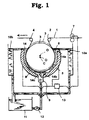
- FIG. 1 An apparatus for electrolytic treatment is illustrated in Figure 1 which comprises a drum roller 3 and electrodes 5, 6 concentrically provided with the drum roller 3 on the outside thereof. That is, the distance between the drum roller 3 and each electrode 5, 6 is kept constant except both ends, and set at a distance selected in the range of 5 to 50 mm.
- the drum roller 3 is movable vertically to transfer the central point O upward from the central point C of the electrodes 5, 6. That is, in the state that the central point O of the drum roller 3 is consistent with the central point C of the electrodes 5, 6, the distance between the circumferential face of the drum roller 3 and the surface of the electrodes 5, 6 is kept constant, as shown by a full line in Figure 1. On the other hand, when the drum roller 3 is moved upward, the lower the position of the electrodes is, the longer the distance between the circumferential face of the drum roller 3 and the surface of the electrodes 5, 6 is. The distance is the greatest at the cut off portions 14b, 14c.
- Both ends 14a, 14b, 14c, 14d (cut off portion) of each electrode 5, 6 is cut off obliquely so as to leave the surface of the drum roller 3 gradually to form a low current density zone.
- a metal web 1 enters horizontally from the right side in the figure, and after passing nip rollers containing an electric supplier roller 7, turns downward by a pass roller 2.
- the electric supplier roller 7 is driven at the same speed as the traveling speed of the metal web 1.
- the metal web 1 is wound around the drum roller 3, while electric treatment is carried out. Then, the metal web 1 leaves the drum roller 3, turns to horizontal direction by a pass roller 4, and further travels.
- An electrolytic solution 8 is put in a circulation tank 11, and supplied from a supply port 9 located at the bottom of the electrolytic cell to fill the space between the drum roller 3 and the electrodes 5, 6 by a pump 12.
- the electrolytic solution 8 overflows from the upper edge of each electrode 5, 6, and returns to the circulation tank 11 through the discharge portion 10a, 10b.
- Alternating waveform current is supplied from an alternating waveform current power supply 13.
- One output terminal of the power supply 13 is connected to the electric supplier roller 7, and the other output terminal is connected to the electrodes 5, 6.
- the power supply 13 is provided with a frequency controller as the frequency-variable means, and the frequency of the output alternating waveform current can be set arbitrarily at an interval of 0.1 Hz.
- the electrolytic conditions are as follows:
- the moved length in the upward direction of the drum roller was 10 %, 20 % and 40 % of the distance between the drum roller (Al web) and the electrode upon they were allocated concentrically.
Landscapes
- Chemical & Material Sciences (AREA)
- Chemical Kinetics & Catalysis (AREA)
- Electrochemistry (AREA)
- Engineering & Computer Science (AREA)
- Materials Engineering (AREA)
- Metallurgy (AREA)
- Organic Chemistry (AREA)
- Printing Plates And Materials Therefor (AREA)
- Electroplating Methods And Accessories (AREA)
Abstract
Description
- This invention relates to an apparatus and method for electrolytic treatment which comprises etching a metal web electrolytically using alternating waveform current continuously, and particularly, relates to an apparatus and method for electrolytic treatment suitable for electrolytic etching of aluminum web during manufacturing a support for planographic printing plate.
- Electrolytic etching of a surface of aluminum, iron or the like is widely utilized, and alternating waveform current is generally used due to required quality and the improvement in reaction efficiency. For example, Japanese Patent KOKOKU 56-19280 discloses an electrolytic etching treatment which can provide excellent roughening as a support for an offset printing plate by using an alternating waveform current impressed so that the electric voltage at anode is made greater than the electric voltage at cathode in electrolytic roughening of an aluminum plate.
- In general, electrolytic etching is carried out at a current density of 10 to 100 A/dm2 in an acidic electrolytic solution, such as 1 to 5 % nitric acid or hydrochloric acid. Upon treating electrolytically an aluminum plate as the metal web,
- These reactions occur alternately according to the frequency of power supply, and, in general, it is possible to obtain a required roughened surface by adjusting these fundamental reactions by controlling electrolytic conditions, such as the type and concentration of electrolytic solution, temperature conditions, current density and charged quantity of electricity.
- Hereupon, in the case of using alternating waveform current, there are differences between the treatment initiating part by the dissolution reaction and the terminating part caused by the current cycle on entering a metal web into an electrolytic bath and on going out of the bath, and shadow unevenness (uneven treatment) occurs in the cross direction to the traveling direction of the metal web. The uneven treatment generates according to the frequency of a power supply. For example, in the case of a treating speed of 50 m/min and a frequency of power supply of 60 Hz, the uneven treatment generates at an interval (pitch) of 1.39 cm in the longitudinal direction of the metal web. In view of massproduction, a higher treating speed and a higher current density treating speed and a higher current density treatment are desired. In the case of high strength aluminum support containing manganese or the like which recently increases, there is a tendency to manufacture a high quality support for planographic printing plate by lowering frequency.
- On the other hand, the degree of the above mentioned ununiformity according to the frequency of power supply becomes stronger by higher treating speed, higher current density or lower frequency due to its generation mechanism.
- In this regard, Japanese Patent KOKAI 1-230800 discloses an electrolytic apparatus which can remove the uneven treatment by providing low current density zones at the front end and rear end of an electrode, and making the remaining portion a constant current density zone. Japanese Patent KOKAI 4-289200 discloses a roughening method using a power supply frequency of 1 to 30 Hz.
- However, according to the conventional methods mentional above, the uneven treatment according to the frequency cannot be removed entirely in the case of high treating speed, high current density or variation of electrolytic solution conditions.
- An object of the invention is to provide an electrolytic treatment apparatus and an electrolytic treatment method which remove the uneven treatment according to the frequency and can achieve high treating speed and high current density treatment.
The inventors investigated eagerly as to the uneven treatment generated on metal web, and as a result, they found that the uneven treatment occurs particularly strongly at the upstream end of the rear electrode in the traveling direction of the metal web in an indirect electric power supply cell. They further found that the uneven treatment is generated caused by the existence of untreating zone between the electrodes, and by a very high current density at that part caused by the electric resistance of the metal web. - Thus, the present invention provides a meted for electrolytic treatment which comprises passing a metal web through an apparatus for electrolytic treatment which comprises a drum roller around which a metal web is wound, arc-shaped electrodes allocated on the outside of the drum roller concentrically with a space, and an electrolytic solution put in the space, and electrolyzing the metal web by applying an electric current to the electrodes, wherein the electrolyzing is carried out in a state that the drum roller has been moved upward from the concentric point.
- By making the drum roller movable, the current density at the ends of the electrodes can be controlled so as to become optimum. When the drum roller is moved upward from the concentrical point, the distance from the ends of electrodes is lengthened to decrease the current density around the end portions of electrodes. The above ends are produced by separating an electrode. A suitable moving range is 10 to 100 %, preferably 10 to 40 %, more preferably 20 to 40 % of the distance between the drum roller and the arc-shaped electrodes upon being located concentrically.
-
- Figure 1 is a schematic section of an apparatus for electrolytic treatment which embodies the invention.
- Figure 2 is a graph indicating variation of current with the position of electrodes and moved distance of the drum roller.
- 1 Metal web
- 2 Pass roller
- 3 Drum roller
- 4 Pass roller
- 5, 6 Electrode
- 7 Electric supplier roller
- 8 Electrolytic solution
- 9 Supply port
- 10a, 10b Discharge portion
- 11 Circulation tank
- 12 Pump
- 13 Power supply
- 14, 14b, 14c, 14d Cut off portion
- O Center of drum roller
- C Center of electrodes
-
- An apparatus for electrolytic treatment is illustrated in Figure 1 which comprises a
drum roller 3 andelectrodes 5, 6 concentrically provided with thedrum roller 3 on the outside thereof. That is, the distance between thedrum roller 3 and eachelectrode 5, 6 is kept constant except both ends, and set at a distance selected in the range of 5 to 50 mm. - The
drum roller 3 is movable vertically to transfer the central point O upward from the central point C of theelectrodes 5, 6. That is, in the state that the central point O of thedrum roller 3 is consistent with the central point C of theelectrodes 5, 6, the distance between the circumferential face of thedrum roller 3 and the surface of theelectrodes 5, 6 is kept constant, as shown by a full line in Figure 1. On the other hand, when thedrum roller 3 is moved upward, the lower the position of the electrodes is, the longer the distance between the circumferential face of thedrum roller 3 and the surface of theelectrodes 5, 6 is. The distance is the greatest at the cut offportions - Both
ends electrode 5, 6 is cut off obliquely so as to leave the surface of thedrum roller 3 gradually to form a low current density zone. Ametal web 1 enters horizontally from the right side in the figure, and after passing nip rollers containing anelectric supplier roller 7, turns downward by apass roller 2. Theelectric supplier roller 7 is driven at the same speed as the traveling speed of themetal web 1. Themetal web 1 is wound around thedrum roller 3, while electric treatment is carried out. Then, themetal web 1 leaves thedrum roller 3, turns to horizontal direction by a pass roller 4, and further travels. - An
electrolytic solution 8 is put in acirculation tank 11, and supplied from a supply port 9 located at the bottom of the electrolytic cell to fill the space between thedrum roller 3 and theelectrodes 5, 6 by apump 12. Theelectrolytic solution 8 overflows from the upper edge of eachelectrode 5, 6, and returns to thecirculation tank 11 through thedischarge portion - Alternating waveform current is supplied from an alternating waveform
current power supply 13. One output terminal of thepower supply 13 is connected to theelectric supplier roller 7, and the other output terminal is connected to theelectrodes 5, 6. Thepower supply 13 is provided with a frequency controller as the frequency-variable means, and the frequency of the output alternating waveform current can be set arbitrarily at an interval of 0.1 Hz. - Using the above electrolytic treatment apparatus, electrolytic etching of an aluminum web was carried out.
- The electrolytic conditions are as follows:
- Aluminum web width:
- 1000 mm
- Treating speed:
- 60 m/min
- Type of electrolytic solution:
- 1 % of nitric acid
- Temperature:
- 40 °C
- Mean current density:
- 60 A/dm2
- Frequency:
- 60.1 - 60.5 Hz
- Distance between drum roller
- (Al web) and electrodes:
- 15 mm
- The moved length in the upward direction of the drum roller was 10 %, 20 % and 40 % of the distance between the drum roller (Al web) and the electrode upon they were allocated concentrically.
- The current variation with the position of the electrodes at each moved position of the drum roller is shown in Figure 2. In the figure, indicated not moved, ▪ indicates moved by 20 %, and ▵ indicates moved by 40 %, respectively. The results in Figure 2 show that current value is decreased with increasing the moved length of drum roller at the cut off
portions - The occurrence of uneven treatment is summarized in Table 1.
Frequency (Hz) Movement of Drum Roller 0 % 10 % 20 % 40 % 60.1 ▵ ○▵ ○ ○ 60.3 ○▵ ○ ○ ○ 60.5 ▵ ○▵ ○ ○ ▵ ... Generated
○▵ ... Slightly generated
○ ... Not or almost not generated
Claims (7)
- An apparatus for electrolytic treatment which comprises a drum roller around which a metal web is wound, arc-shaped electrodes allocated on the outside of the drum roller concentrically with a space, and an electrolytic solution put in the space, wherein the drum roller is made movable in the vertical direction.
- The apparatus of claim 1 wherein the drum roller and the arc-shaped electrodes are arranged with a distance of 5 to 50 mm, and the movable range of the drum roller is at least up to 100 % of the distance in the upward direction.
- The apparatus of claim 2 wherein the metal web is an aluminum web.
- A method for electrolytic treatment which comprises passing a metal web through an apparatus for electrolytic treatment which comprises a drum roller around which a metal web is wound, arc-shaped electrodes allocated on the outside of the drum roller concentrically with a space, and an electrolytic solution put in the space, and electrolyzing the metal web by applying an electric current to the electrodes, wherein the electrolyzing is carried out in a state that the drum roller has been moved upward from the concentric point.
- The method of claim 4 wherein the drum roller and the arc-shaped electrodes are arranged with a distance of 5 to 50 mm, and the moved distance of the drum roller is 10 to 100 % of the distance between the drum roller and the arc-shaped electrodes in the upward direction.
- The method of claim 5 wherein the moved distance is 10 to 40 %.
- The method of claim 5 wherein the moved distance is 20 to 40 %.
Applications Claiming Priority (2)
| Application Number | Priority Date | Filing Date | Title |
|---|---|---|---|
| JP4686499 | 1999-02-24 | ||
| JP11046864A JP2000239900A (en) | 1999-02-24 | 1999-02-24 | Electrolytic treatment apparatus and electrolytic treatment |
Publications (2)
| Publication Number | Publication Date |
|---|---|
| EP1031648A1 true EP1031648A1 (en) | 2000-08-30 |
| EP1031648B1 EP1031648B1 (en) | 2003-09-10 |
Family
ID=12759217
Family Applications (1)
| Application Number | Title | Priority Date | Filing Date |
|---|---|---|---|
| EP00103792A Expired - Lifetime EP1031648B1 (en) | 1999-02-24 | 2000-02-23 | Apparatus and method for electrolytic treatment |
Country Status (4)
| Country | Link |
|---|---|
| US (1) | US6325912B1 (en) |
| EP (1) | EP1031648B1 (en) |
| JP (1) | JP2000239900A (en) |
| DE (1) | DE60005076T2 (en) |
Citations (2)
| Publication number | Priority date | Publication date | Assignee | Title |
|---|---|---|---|---|
| EP0387750A1 (en) * | 1989-03-14 | 1990-09-19 | Fuji Photo Film Co., Ltd. | Electrolytic treatment apparatus |
| EP0475026A1 (en) * | 1990-09-07 | 1992-03-18 | International Business Machines Corporation | Apparatus, electrochemical process, and electrolyte for microfinishing stainless steel print bands |
Family Cites Families (3)
| Publication number | Priority date | Publication date | Assignee | Title |
|---|---|---|---|---|
| JPS62136596A (en) * | 1985-12-09 | 1987-06-19 | Fuji Photo Film Co Ltd | Continuous electrolytic treatment device for metallic web |
| JP2581954B2 (en) * | 1988-07-04 | 1997-02-19 | 富士写真フイルム株式会社 | Electrolytic treatment of aluminum support for lithographic printing plate |
| JP2000017500A (en) * | 1998-06-26 | 2000-01-18 | Fuji Photo Film Co Ltd | Electrolyzer and electrolytic method |
-
1999
- 1999-02-24 JP JP11046864A patent/JP2000239900A/en active Pending
-
2000
- 2000-02-23 EP EP00103792A patent/EP1031648B1/en not_active Expired - Lifetime
- 2000-02-23 DE DE60005076T patent/DE60005076T2/en not_active Expired - Fee Related
- 2000-02-24 US US09/511,990 patent/US6325912B1/en not_active Expired - Fee Related
Patent Citations (2)
| Publication number | Priority date | Publication date | Assignee | Title |
|---|---|---|---|---|
| EP0387750A1 (en) * | 1989-03-14 | 1990-09-19 | Fuji Photo Film Co., Ltd. | Electrolytic treatment apparatus |
| EP0475026A1 (en) * | 1990-09-07 | 1992-03-18 | International Business Machines Corporation | Apparatus, electrochemical process, and electrolyte for microfinishing stainless steel print bands |
Also Published As
| Publication number | Publication date |
|---|---|
| US6325912B1 (en) | 2001-12-04 |
| DE60005076T2 (en) | 2004-04-01 |
| EP1031648B1 (en) | 2003-09-10 |
| JP2000239900A (en) | 2000-09-05 |
| DE60005076D1 (en) | 2003-10-16 |
Similar Documents
| Publication | Publication Date | Title |
|---|---|---|
| US6143158A (en) | Method for producing an aluminum support for a lithographic printing plate | |
| JPH05195300A (en) | Electrolytic treating device | |
| JPH01141094A (en) | Production of aluminum base for printing plate | |
| JPS6237718B2 (en) | ||
| JP2520685B2 (en) | Electrolytic treatment equipment | |
| JPH08316111A (en) | Apparatus and method for manufacturing electrode foil for aluminum electrolytic capacitor | |
| JPH0148360B2 (en) | ||
| JPS6316000B2 (en) | ||
| EP1031648A1 (en) | Apparatus and method for electrolytic treatment | |
| EP0967302B1 (en) | Apparatus and method for electrolytic treatment | |
| EP0387750B1 (en) | Electrolytic treatment apparatus | |
| JP2581954B2 (en) | Electrolytic treatment of aluminum support for lithographic printing plate | |
| JP2707381B2 (en) | Electrolytic treatment of aluminum support for printing plate | |
| JP2003171800A (en) | Electrolyzer | |
| JP2001140100A (en) | Device for electrolyzing metallic sheet and electrode for electrolyzing metallic sheet | |
| JPS6357515B2 (en) | ||
| JPH05301478A (en) | Support of planograpahic printing plate and production thereof | |
| EP0502507A1 (en) | Method and apparatus for electrolytic treatment | |
| RU1808886C (en) | Device for electrochemical cleaning of strips | |
| JPS6358918B2 (en) | ||
| JPH01252800A (en) | Electrolytic treatment equipment | |
| JP2767699B2 (en) | Electrolytic treatment equipment | |
| JP4189053B2 (en) | High speed electrolytic descaling method for stainless steel | |
| JP4157442B2 (en) | Direct conduction type continuous electrolytic etching method and direct conduction type continuous electrolytic etching apparatus for low iron loss unidirectional silicon steel sheet | |
| JPH10280199A (en) | Electrolytic treatment |
Legal Events
| Date | Code | Title | Description |
|---|---|---|---|
| PUAI | Public reference made under article 153(3) epc to a published international application that has entered the european phase |
Free format text: ORIGINAL CODE: 0009012 |
|
| AK | Designated contracting states |
Kind code of ref document: A1 Designated state(s): DE GB |
|
| AX | Request for extension of the european patent |
Free format text: AL;LT;LV;MK;RO;SI |
|
| 17P | Request for examination filed |
Effective date: 20010131 |
|
| AKX | Designation fees paid |
Free format text: DE GB |
|
| 17Q | First examination report despatched |
Effective date: 20020904 |
|
| GRAH | Despatch of communication of intention to grant a patent |
Free format text: ORIGINAL CODE: EPIDOS IGRA |
|
| GRAS | Grant fee paid |
Free format text: ORIGINAL CODE: EPIDOSNIGR3 |
|
| GRAA | (expected) grant |
Free format text: ORIGINAL CODE: 0009210 |
|
| AK | Designated contracting states |
Kind code of ref document: B1 Designated state(s): DE GB |
|
| REG | Reference to a national code |
Ref country code: GB Ref legal event code: FG4D |
|
| REF | Corresponds to: |
Ref document number: 60005076 Country of ref document: DE Date of ref document: 20031016 Kind code of ref document: P |
|
| PLBE | No opposition filed within time limit |
Free format text: ORIGINAL CODE: 0009261 |
|
| STAA | Information on the status of an ep patent application or granted ep patent |
Free format text: STATUS: NO OPPOSITION FILED WITHIN TIME LIMIT |
|
| 26N | No opposition filed |
Effective date: 20040614 |
|
| REG | Reference to a national code |
Ref country code: GB Ref legal event code: 732E |
|
| PGFP | Annual fee paid to national office [announced via postgrant information from national office to epo] |
Ref country code: DE Payment date: 20090206 Year of fee payment: 10 |
|
| PGFP | Annual fee paid to national office [announced via postgrant information from national office to epo] |
Ref country code: GB Payment date: 20090217 Year of fee payment: 10 |
|
| GBPC | Gb: european patent ceased through non-payment of renewal fee |
Effective date: 20100223 |
|
| PG25 | Lapsed in a contracting state [announced via postgrant information from national office to epo] |
Ref country code: DE Free format text: LAPSE BECAUSE OF NON-PAYMENT OF DUE FEES Effective date: 20100901 |
|
| PG25 | Lapsed in a contracting state [announced via postgrant information from national office to epo] |
Ref country code: GB Free format text: LAPSE BECAUSE OF NON-PAYMENT OF DUE FEES Effective date: 20100223 |