EP1031439A2 - A motor vehicle wheel hub bearing and a method for mounting the bearing onto a motor vehicle suspension - Google Patents
A motor vehicle wheel hub bearing and a method for mounting the bearing onto a motor vehicle suspension Download PDFInfo
- Publication number
- EP1031439A2 EP1031439A2 EP00103227A EP00103227A EP1031439A2 EP 1031439 A2 EP1031439 A2 EP 1031439A2 EP 00103227 A EP00103227 A EP 00103227A EP 00103227 A EP00103227 A EP 00103227A EP 1031439 A2 EP1031439 A2 EP 1031439A2
- Authority
- EP
- European Patent Office
- Prior art keywords
- strut
- axial
- bearing
- outer race
- tubular
- Prior art date
- Legal status (The legal status is an assumption and is not a legal conclusion. Google has not performed a legal analysis and makes no representation as to the accuracy of the status listed.)
- Granted
Links
Images


Classifications
-
- F—MECHANICAL ENGINEERING; LIGHTING; HEATING; WEAPONS; BLASTING
- F16—ENGINEERING ELEMENTS AND UNITS; GENERAL MEASURES FOR PRODUCING AND MAINTAINING EFFECTIVE FUNCTIONING OF MACHINES OR INSTALLATIONS; THERMAL INSULATION IN GENERAL
- F16C—SHAFTS; FLEXIBLE SHAFTS; ELEMENTS OR CRANKSHAFT MECHANISMS; ROTARY BODIES OTHER THAN GEARING ELEMENTS; BEARINGS
- F16C35/00—Rigid support of bearing units; Housings, e.g. caps, covers
- F16C35/08—Rigid support of bearing units; Housings, e.g. caps, covers for spindles
- F16C35/12—Rigid support of bearing units; Housings, e.g. caps, covers for spindles with ball or roller bearings
-
- B—PERFORMING OPERATIONS; TRANSPORTING
- B60—VEHICLES IN GENERAL
- B60B—VEHICLE WHEELS; CASTORS; AXLES FOR WHEELS OR CASTORS; INCREASING WHEEL ADHESION
- B60B27/00—Hubs
- B60B27/0078—Hubs characterised by the fixation of bearings
- B60B27/0089—Hubs characterised by the fixation of bearings caulking to fix outer race
-
- B—PERFORMING OPERATIONS; TRANSPORTING
- B60—VEHICLES IN GENERAL
- B60B—VEHICLE WHEELS; CASTORS; AXLES FOR WHEELS OR CASTORS; INCREASING WHEEL ADHESION
- B60B27/00—Hubs
-
- B—PERFORMING OPERATIONS; TRANSPORTING
- B60—VEHICLES IN GENERAL
- B60B—VEHICLE WHEELS; CASTORS; AXLES FOR WHEELS OR CASTORS; INCREASING WHEEL ADHESION
- B60B27/00—Hubs
- B60B27/0005—Hubs with ball bearings
-
- B—PERFORMING OPERATIONS; TRANSPORTING
- B60—VEHICLES IN GENERAL
- B60B—VEHICLE WHEELS; CASTORS; AXLES FOR WHEELS OR CASTORS; INCREASING WHEEL ADHESION
- B60B27/00—Hubs
- B60B27/0094—Hubs one or more of the bearing races are formed by the hub
-
- F—MECHANICAL ENGINEERING; LIGHTING; HEATING; WEAPONS; BLASTING
- F16—ENGINEERING ELEMENTS AND UNITS; GENERAL MEASURES FOR PRODUCING AND MAINTAINING EFFECTIVE FUNCTIONING OF MACHINES OR INSTALLATIONS; THERMAL INSULATION IN GENERAL
- F16C—SHAFTS; FLEXIBLE SHAFTS; ELEMENTS OR CRANKSHAFT MECHANISMS; ROTARY BODIES OTHER THAN GEARING ELEMENTS; BEARINGS
- F16C19/00—Bearings with rolling contact, for exclusively rotary movement
- F16C19/02—Bearings with rolling contact, for exclusively rotary movement with bearing balls essentially of the same size in one or more circular rows
- F16C19/14—Bearings with rolling contact, for exclusively rotary movement with bearing balls essentially of the same size in one or more circular rows for both radial and axial load
- F16C19/18—Bearings with rolling contact, for exclusively rotary movement with bearing balls essentially of the same size in one or more circular rows for both radial and axial load with two or more rows of balls
- F16C19/181—Bearings with rolling contact, for exclusively rotary movement with bearing balls essentially of the same size in one or more circular rows for both radial and axial load with two or more rows of balls with angular contact
- F16C19/183—Bearings with rolling contact, for exclusively rotary movement with bearing balls essentially of the same size in one or more circular rows for both radial and axial load with two or more rows of balls with angular contact with two rows at opposite angles
- F16C19/184—Bearings with rolling contact, for exclusively rotary movement with bearing balls essentially of the same size in one or more circular rows for both radial and axial load with two or more rows of balls with angular contact with two rows at opposite angles in O-arrangement
-
- F—MECHANICAL ENGINEERING; LIGHTING; HEATING; WEAPONS; BLASTING
- F16—ENGINEERING ELEMENTS AND UNITS; GENERAL MEASURES FOR PRODUCING AND MAINTAINING EFFECTIVE FUNCTIONING OF MACHINES OR INSTALLATIONS; THERMAL INSULATION IN GENERAL
- F16C—SHAFTS; FLEXIBLE SHAFTS; ELEMENTS OR CRANKSHAFT MECHANISMS; ROTARY BODIES OTHER THAN GEARING ELEMENTS; BEARINGS
- F16C35/00—Rigid support of bearing units; Housings, e.g. caps, covers
- F16C35/04—Rigid support of bearing units; Housings, e.g. caps, covers in the case of ball or roller bearings
- F16C35/06—Mounting or dismounting of ball or roller bearings; Fixing them onto shaft or in housing
- F16C35/067—Fixing them in a housing
-
- F—MECHANICAL ENGINEERING; LIGHTING; HEATING; WEAPONS; BLASTING
- F16—ENGINEERING ELEMENTS AND UNITS; GENERAL MEASURES FOR PRODUCING AND MAINTAINING EFFECTIVE FUNCTIONING OF MACHINES OR INSTALLATIONS; THERMAL INSULATION IN GENERAL
- F16C—SHAFTS; FLEXIBLE SHAFTS; ELEMENTS OR CRANKSHAFT MECHANISMS; ROTARY BODIES OTHER THAN GEARING ELEMENTS; BEARINGS
- F16C2326/00—Articles relating to transporting
- F16C2326/01—Parts of vehicles in general
- F16C2326/02—Wheel hubs or castors
Definitions
- the present invention relates to a motor vehicle wheel hub bearing of the type identified in the preamble of Claim 1.
- the invention further relates to a method for mounting the bearing on the suspension strut of a motor vehicle.
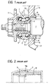
- a bearing generally indicated 1 comprises a radially outer race 2 which has two rolling raceways for respective sets of rolling balls 3.
- the balls can rotate on radially inner raceways 4 and 5 which are mounted on a flanged hub 6 fixed for rotation in a known way to an axle 7.
- the outer race 2 includes an annular main portion 6 which extends to only one axially inner side (that is to say facing towards the interior of the vehicle) forming an axial tubular projection 10 which defines, with the main annular portion 9, an axial abutment shoulder 11 able to abut against the outer lateral surface 12 of the strut 13.
- a cylindrical seat 14 is formed in the strut 13, into which the outer cylindrical surface 15 of the tubular projection 10 is force fitted.
- This tubular projection has an axial dimension greater than the axial thickness of the strut 13, in such a way that the axially inner rim of the tubular projection 10 can be folded and radially outwardly deformed against the axially inner lateral surface 16 of the strut 13 by means of a cold-rolling plastic deformation operation, to obtain a rolled edge 17 which thus axially fixes the bearing onto the suspension strut.
- This arrangement which is advantageous as it makes it possible to fix the bearing onto the suspension without causing deformations in the region of the raceways of the outer race of the bearing, does, however, have a disadvantage due to the fact that it requires very accurate mechanical finishing in particular for the formation of the shoulder 11.
- the outer race of the bearing is moreover made heavier by that portion of the material which forms the said shoulder.
- An object of the invention is to provide a bearing of the above-identified type, having an outer race of less weight and which involves, for its finishing, a simpler and more rugged turning operation, which is therefore economically advantageous.
- Another object of the invention is to provide a bearing in which the material from which it is made is utilised in an optimal manner.
- a yet further object is to centre a bearing in an improved and more "flexible” manner on the motor vehicle suspension.
- a bearing according to the present invention comprises a radially outer race 2, described in more detail below, a pair of radially inner races or half-races 4 to 5, and two sets of rolling elements 3, in this example balls, radially interposed between the outer race 2 and the inner half-races 4 and 5.
- the outer race 2 comprises a central main annular portion 9 in which the raceways are formed for the rolling elements 3.
- the outer race 2 has an outer cylindrical surface 18 adapted to be inserted in a cylindrical seat 14 formed in the strut 13 of a suspension.
- the seat 14 and the cylindrical surface 18 are so dimensioned as to provide some radial interference requiring a forced fitting of the bearing in the strut, to obtain a better locking of the bearing.
- the outer surface 18 extends over the whole of the axial dimension of the outer race 2 and has a greater axial dimension than that of the strut 13.
- the two axially opposite ends of the cylindrical surface 18 comprise respective axial tubular opposite end projections 19 and 20 which extend from the central main portion 9; the tubular projections 19 and 20 are shaped and outwardly dimensioned to be plastically deformed, cold, preferably by being rolled radially outwardly towards the inner and outer lateral surfaces 16 and 12 of the strut 13 so as to assume the configuration illustrated in Figure 3, and in broken outline in Figure 4, as indicated by the reference numerals 19a and 20a.
- the radially inner races 4 and 5 have an overall axial dimension not greater than the axial thickness s of the strut 13.
- the sequence of operations for mounting the bearing onto the strut provides that the complete bearing of outer race, inner race and rolling elements is inserted into the seat 14 of the strut.
- the outer race 2 is inserted forcibly.
- the insertion could for example by effected by means of a tool 21 schematically illustrated in Figure 5 which has a first axial abutment surface 22 and a second axial abutment surface 23, axially spaced from one another by a predetermined distance e .
- the first abutment surface 22 presses the outer, undeformed face 24 of the axially outer extension 20 in the axial direction indicated by the arrow A until the second axial abutment surface 23 engages against a reference surface 25 fixed to the strut, in this case represented by a zone 12 of the outer surface of the strut close to the cylindrical seat 14.
- the distance e is predetermined in such a way that in the abutment configuration the ends of the tubular projections 19 and 20 project, in the undeformed condition before rolling, by respective distances e ' and e '' beyond the lateral surfaces 16 and 12 of the strut.
- the distances e ' and e '' can be the same or slightly different depending on requirements, thus making it possible to fix the bearing to the strut in a plurality of different axial positions.
- the distances by which the said undeformed ends project beyond the lateral surfaces of the strut will be such as to allow the formation of corresponding rolled edges 19a and 20a effective in axially fixing of the bearing onto the strut.
- the rolling operations can be equally well performed simultaneously on both projections or, alternatively, in two successive steps, resisting axial movement of the outer race 2 by means of the same tool 21 utilised to determine the desired axial position of the outer race with respect to the strut.
- the deformed edges 19a and 20a each have an axial thickness b less than or equal to the radial thickness t of the tubular projections 19 and 20 in their undeformed condition, as indicated in Figure 4.
- connection 26 For the purposes of improving the fixing of the bearing to the strut it is also advantageous to form a bend or a circumferentially curved connection 26 on the strut, in the connection region between the opposite lateral surfaces 16, 12 and the cylindrical seat 14, each preferably having an axial extent h not greater than 3 mm.
- the outer race of the bearing according to the present invention is obtained from a forged blank of very much simpler form, as schematically indicated by the broken outline C in Figure 6. It will be noted that on the radially outer surface of the outer race it is not necessary to form with precision the conventional shoulder 11 of Figure 2.
- outer races obtained according to the invention are lighter and have an axially symmetrical structure so that they can be mounted indifferently with either of their faces being the frontal face thus simplifying mounting.
Landscapes
- Engineering & Computer Science (AREA)
- Mechanical Engineering (AREA)
- General Engineering & Computer Science (AREA)
- Rolling Contact Bearings (AREA)
- Vehicle Body Suspensions (AREA)
- Mounting Of Bearings Or Others (AREA)
Abstract
Description
- The present invention relates to a motor vehicle wheel hub bearing of the type identified in the preamble of
Claim 1. The invention further relates to a method for mounting the bearing on the suspension strut of a motor vehicle. - A bearing of the said type, known from European Patent Application EP-A-0 794 072 is illustrated in Figure 1. With reference to Figure 1, a bearing generally indicated 1 comprises a radially
outer race 2 which has two rolling raceways for respective sets ofrolling balls 3. The balls can rotate on radiallyinner raceways hub 6 fixed for rotation in a known way to anaxle 7. - The
outer race 2 includes an annularmain portion 6 which extends to only one axially inner side (that is to say facing towards the interior of the vehicle) forming an axialtubular projection 10 which defines, with the mainannular portion 9, anaxial abutment shoulder 11 able to abut against the outerlateral surface 12 of thestrut 13. - A
cylindrical seat 14 is formed in thestrut 13, into which the outercylindrical surface 15 of thetubular projection 10 is force fitted. This tubular projection has an axial dimension greater than the axial thickness of thestrut 13, in such a way that the axially inner rim of thetubular projection 10 can be folded and radially outwardly deformed against the axially innerlateral surface 16 of thestrut 13 by means of a cold-rolling plastic deformation operation, to obtain a rollededge 17 which thus axially fixes the bearing onto the suspension strut. - This arrangement, which is advantageous as it makes it possible to fix the bearing onto the suspension without causing deformations in the region of the raceways of the outer race of the bearing, does, however, have a disadvantage due to the fact that it requires very accurate mechanical finishing in particular for the formation of the
shoulder 11. The outer race of the bearing is moreover made heavier by that portion of the material which forms the said shoulder. - An object of the invention is to provide a bearing of the above-identified type, having an outer race of less weight and which involves, for its finishing, a simpler and more rugged turning operation, which is therefore economically advantageous.
- Another object of the invention is to provide a bearing in which the material from which it is made is utilised in an optimal manner.
- A yet further object is to centre a bearing in an improved and more "flexible" manner on the motor vehicle suspension.
- These objects are achieved according to the present invention by a bearing having the characteristics set out in
Claim 1. - According to another aspect of the invention, these objects are achieved by a method as defined in
Claim 6. - Further important characteristics of the invention are specified in the dependent claims.
- The characteristics and advantages of the present invention will become apparent from the detailed description of various embodiments thereof, given with reference to the attached drawings, given by way of non-limitative example, in which:
- Figure 1 is a vertical axial section of a prior art wheel hub bearing mounted on a motor vehicle strut;
- Figure 2 is a partial axial section of a detail of the bearing of Figure 1;
- Figure 3 is an axial sectional view of a motor vehicle wheel hub having a bearing according to the present invention fixed to the suspension strut of a motor vehicle;
- Figure 4 is a view in axial section of the outer race of the bearing of Figure 3;
- Figure 5 illustrates a mounting phase of the bearing onto the suspension; and
- Figure 6 is a partial view in axial section of a forged blank from which an outer race for a bearing according to the invention is formed.
-
- Referring to Figures 3 and 4, and utilising the same reference numerals already adopted for Figure 1, a bearing according to the present invention comprises a radially
outer race 2, described in more detail below, a pair of radially inner races or half-races 4 to 5, and two sets ofrolling elements 3, in this example balls, radially interposed between theouter race 2 and the inner half-races - Making reference now in particular to Figure 4, the
outer race 2 comprises a central mainannular portion 9 in which the raceways are formed for therolling elements 3. Theouter race 2 has an outercylindrical surface 18 adapted to be inserted in acylindrical seat 14 formed in thestrut 13 of a suspension. Preferably, theseat 14 and thecylindrical surface 18 are so dimensioned as to provide some radial interference requiring a forced fitting of the bearing in the strut, to obtain a better locking of the bearing. - The
outer surface 18 extends over the whole of the axial dimension of theouter race 2 and has a greater axial dimension than that of thestrut 13. - The two axially opposite ends of the
cylindrical surface 18 comprise respective axial tubularopposite end projections main portion 9; thetubular projections lateral surfaces strut 13 so as to assume the configuration illustrated in Figure 3, and in broken outline in Figure 4, as indicated by thereference numerals - Preferably, the radially
inner races strut 13. - The sequence of operations for mounting the bearing onto the strut provides that the complete bearing of outer race, inner race and rolling elements is inserted into the
seat 14 of the strut. In the preferred embodiment, in which there is provided some radial interference between thesurface 18 of theouter race 2 and theseat 14 of the strut, theouter race 2 is inserted forcibly. The insertion could for example by effected by means of atool 21 schematically illustrated in Figure 5 which has a firstaxial abutment surface 22 and a secondaxial abutment surface 23, axially spaced from one another by a predetermined distance e. - The
first abutment surface 22 presses the outer,undeformed face 24 of the axiallyouter extension 20 in the axial direction indicated by the arrow A until the secondaxial abutment surface 23 engages against areference surface 25 fixed to the strut, in this case represented by azone 12 of the outer surface of the strut close to thecylindrical seat 14. - The distance e is predetermined in such a way that in the abutment configuration the ends of the
tubular projections lateral surfaces edges - The rolling operations can be equally well performed simultaneously on both projections or, alternatively, in two successive steps, resisting axial movement of the
outer race 2 by means of thesame tool 21 utilised to determine the desired axial position of the outer race with respect to the strut. - In the preferred embodiment of the method according to the invention, the
deformed edges tubular projections - For the purposes of improving the fixing of the bearing to the strut it is also advantageous to form a bend or a circumferentially
curved connection 26 on the strut, in the connection region between the oppositelateral surfaces cylindrical seat 14, each preferably having an axial extent h not greater than 3 mm. - As may be appreciated, the outer race of the bearing according to the present invention is obtained from a forged blank of very much simpler form, as schematically indicated by the broken outline C in Figure 6. It will be noted that on the radially outer surface of the outer race it is not necessary to form with precision the
conventional shoulder 11 of Figure 2. - Moreover, with particular reference to Figure 2, the material conventionally used to form the
reinforcement region 11a of theshoulder 11 is saved: as a consequence, the working operations will be expedited with respect to the prior art discussed in the introduction, in that the turning operation to obtain a cylindrical surface is simpler and faster. - In addition, the quantity of excess metal to remove from the partly worked workpiece will generally be less as will be apparent from comparison of the broken outlines in Figures 2 and 6.
- Finally, the outer races obtained according to the invention are lighter and have an axially symmetrical structure so that they can be mounted indifferently with either of their faces being the frontal face thus simplifying mounting.
- Naturally, the principle of the invention remaining the same, its details can be varied with respect to what has been described in the present example. In particular, it would be possible to form a plurality of radial recesses (or projections) in one or both
lateral surfaces edges
Claims (15)
- A bearing for a motor vehicle wheel hub, comprising an outer race (2) which can be mounted in a cylindrical seat (14) formed in a suspension strut (13) and fixed in the said seat by cold forming, in which the said outer race (2) has:a main annular portion (9) forming raceways for rolling elements (3);an outer cylindrical surface (18) to be fitted in the said seat (14);
characterised in that the cylindrical surface (18) extends over the whole axial dimension of the outer race (2) and has an axial dimension greater than that of the strut (13), and in that the two opposite axial ends of the cylindrical surface (18) comprise respective axial tubular projections (19, 20) which extend from the said main portion (9); the said tubular projections (19, 20) being dimensioned so that their ends can be plastically deformed by cold forming radially outwardly towards respective opposite lateral surfaces (16, 12) of the strut so as to fix the bearing to the strut. - A bearing according to Claim 1, characterised in that the said main annular portion (9) is substantially central.
- A bearing according to Claim 2, characterised in that the said outer race (2) has an axially symmetrical shape.
- A bearing according to Claim 1, characterised in that the said tubular projections (19, 20) are dimensioned in such a way that in the undeformed condition before being cold formed their opposite ends extend beyond the said lateral surfaces (12, 16) by respective distances (e', e'') so as to allow the bearing to be fixed to the strut in a plurality of axially different positions.
- A bearing according to Claim 1, characterised in that it comprises one or more radially inner races (4, 5) having an overall axial dimension not greater than the axial thickness (s) of the strut (13).
- A method for mounting a motor vehicle wheel hub bearing to a suspension strut, the method comprising the following steps:(a) providing a strut (13) of a suspension having an axial cylindrical seat (14) extending between two opposite lateral surfaces (16, 12);(b) providing a bearing comprising an outer race (2) having:a main annular portion (9) forming raceways for rolling elements (3); and
an outer cylindrical surface (18) which can be inserted into the said seat (14) of the strut, the said cylindrical surface (18) extending over the whole of the axial dimension of the outer race (2) and having a greater axial dimension than the axial thickness of the strut (13); the two opposite axial ends of the cylindrical surface (18) being constituted by respective axial tubular projections (19, 20) which extend from the said main portion (9);(c) inserting the outer ring (2) into the seat (14) of the strut in such a way as to leave opposite end portions of the tubular projections (19, 20) projecting beyond the said opposite lateral surfaces (16, 12) by predetermined distances (e', e'');(d) cold forming the said end portions in radially outwardly directions towards the said respective opposite lateral surfaces (16, 12) of the strut (13), thereby forming deformed edges (19a, 20a) which fix the bearing to the strut (13). - A method according to Claim 6, characterised in that the said cold forming step (d) forms deformed edges (19a, 20a) each having an axial thickness (b) less than or equal to the radial thickness (t) of the tubular projections (19, 20) in the undeformed condition.
- A method according to Claim 6, characterised in that the said step (a) further comprises the step of:(a1) forming chamfers, bevels or circumferentially curved connections (26) on the strut (13), in correspondence with the connection region between the said opposite lateral surfaces (16, 12) and the said cylindrical seat (14).
- A method according to Claim 8, characterised in that the said chamfers, bevels or curved connections (26) each have an axial extent (h) not greater than 3 mm.
- A method according to Claim 6, characterised in that the said cold deformation step (d) further comprises the following steps in succession:(d1) deforming one of the tubular end portions (19) while resisting axial movement of the outer race (2) by means of a tool (21) acting on the other tubular end portion and shaped (22, 23) to guarantee the desired axial positioning of the outer race (2) with respect to the strut (13);(d2) subsequently deforming the end of the other tubular portion (20).
- A method according to Claim 6, characterised in that in the said cold deformation step (d) both the ends of the tubular portions (19, 20) are simultaneously deformed.
- A method according to Claim 6, characterised in that the said insertion step (c) is effected by utilising a tool (21) which hasa first axial abutment surface (22) able to engage an axially outer side (24) of the axial outer tubular projection (20); anda second axial abutment surface (23) able to engage against a reference surface (25) fixed to the strut, said first and second surfaces (22, 23) being axially spaced from one another by a predetermined distance (e) to position the opposite ends of the tubular projections (19, 20) to project by respective predetermined distances (e', e'') beyond the said lateral surfaces (16, 12) of the strut.
- A method according to Claim 6, characterised in that the said insertion step (c) is effected by utilising a tool (21) which hasa first axial abutment surface (22) able to engage an axially outer side (24) of the axially outer tubular projection (20); anda second axial abutment surface (23) able to engage against a reference surface (25) fixed to the strut, said first and second surfaces (22, 23) being axially spaced from one another by a predetermined distance (e) to position the opposite ends of the tubular projections (19, 20) to project by respective predetermined distances (e', e'') beyond the said lateral surfaces (16, 12) of the strut.
- A method according to Claim 6, 12 or 13, characterised in that the said distances (e', e'') are equal.
- A method according to Claim 6, 12 or 13, characterised in that the said distances (e', e'') are different from one another.
Applications Claiming Priority (2)
| Application Number | Priority Date | Filing Date | Title |
|---|---|---|---|
| IT1999TO000142A IT1308389B1 (en) | 1999-02-24 | 1999-02-24 | BEARING FOR THE WHEEL HUB OF A MOTOR VEHICLE AND PROCEDURE FOR ASSEMBLING THE BEARING ON THE SUSPENSION OF A MOTOR VEHICLE. |
| ITTO990142 | 1999-02-24 |
Publications (3)
| Publication Number | Publication Date |
|---|---|
| EP1031439A2 true EP1031439A2 (en) | 2000-08-30 |
| EP1031439A3 EP1031439A3 (en) | 2003-07-09 |
| EP1031439B1 EP1031439B1 (en) | 2005-04-27 |
Family
ID=11417522
Family Applications (1)
| Application Number | Title | Priority Date | Filing Date |
|---|---|---|---|
| EP00103227A Expired - Lifetime EP1031439B1 (en) | 1999-02-24 | 2000-02-17 | A motor vehicle wheel hub bearing and a method for mounting the bearing onto a motor vehicle suspension |
Country Status (6)
| Country | Link |
|---|---|
| US (1) | US6322253B1 (en) |
| EP (1) | EP1031439B1 (en) |
| JP (1) | JP4464513B2 (en) |
| KR (1) | KR100650221B1 (en) |
| DE (1) | DE60019662T2 (en) |
| IT (1) | IT1308389B1 (en) |
Cited By (6)
| Publication number | Priority date | Publication date | Assignee | Title |
|---|---|---|---|---|
| DE10225878A1 (en) * | 2001-06-12 | 2003-04-30 | Skf Ind Spa | Bearing and suspension stand assembly |
| EP1424217A2 (en) * | 2002-11-26 | 2004-06-02 | Delphi Technologies, Inc. | Fixation of wheel bearing to vehicle suspension |
| WO2005008085A1 (en) * | 2003-07-10 | 2005-01-27 | Fag Kugelfischer Ag & Co. Ohg | Bearing ring and wheel bearing unit |
| EP1672230A1 (en) * | 2004-12-14 | 2006-06-21 | Aktiebolaget SKF | A bearing unit for the hub of a motor vehicle wheel |
| EP1674748A1 (en) * | 2004-12-22 | 2006-06-28 | Ford Global Technologies, LLC | A method of mounting a wheel hub bearing assembly to a knuckle of a vehicle suspension and a vehicle suspension knuckle suitable for such mounting |
| EP2354477A3 (en) * | 2010-01-27 | 2012-04-04 | Schaeffler Technologies AG & Co. KG | Camshaft with a roller bearing, installation assembly for a camshaft with a roller bearing and method for producing same |
Families Citing this family (13)
| Publication number | Priority date | Publication date | Assignee | Title |
|---|---|---|---|---|
| IT1320569B1 (en) * | 2000-07-31 | 2003-12-10 | Skf Ind Spa | BEARING-HUB ASSEMBLY FOR A MOTOR VEHICLE WHEEL. |
| KR20030014800A (en) * | 2001-08-13 | 2003-02-20 | 현대자동차주식회사 | structure of drive wheel front axle for vehicle |
| ITTO20010188U1 (en) * | 2001-10-10 | 2003-04-10 | Skf Ind Spa | HUB AND BRAKE ROTOR ASSEMBLY FOR A VEHICLE WHEEL. |
| ITTO20010229U1 (en) * | 2001-12-10 | 2003-06-10 | Skf Ind Spa | INTEGRATED GROUP FOR THE CONNECTION OF A HUB AND OTHER BODIES TO THE SUSPENSION OF THE WHEEL OF A VEHICLE. |
| ITTO20020205A1 (en) * | 2002-03-12 | 2003-09-12 | Skf Ind Spa | BEARING-HUB ASSEMBLY FOR WHEELS OF VEHICLES WITH SENSOR. |
| DE10359646A1 (en) * | 2003-12-18 | 2005-07-28 | Fag Kugelfischer Ag | Wheel bearing in a wheel carrier |
| DE102004055205A1 (en) * | 2004-11-16 | 2006-05-18 | Fag Kugelfischer Ag & Co. Ohg | Unit of at least one carrier and a wheel bearing |
| DE102006048261B4 (en) * | 2006-10-12 | 2017-06-22 | Schaeffler Technologies AG & Co. KG | Radial rolling bearing, which is destructible dismantled |
| EP2120315B1 (en) * | 2008-05-15 | 2014-02-26 | Siemens Aktiengesellschaft | Drive device |
| US20110097027A1 (en) * | 2009-10-26 | 2011-04-28 | Jong Soon Im | Outer ring for wheel bearing |
| ITTO20130904A1 (en) | 2013-11-07 | 2015-05-08 | Skf Ab | BEARING GROUP-HUB WITH LIGHT ALLOY HUB |
| EP2957432B1 (en) | 2014-06-20 | 2018-01-31 | Aktiebolaget SKF | Hub-bearing having a light alloy rotor-hub |
| US9694627B2 (en) | 2015-06-29 | 2017-07-04 | Aktiebolaget Skf | Hub-bearing having a light alloy rotor-hub |
Family Cites Families (48)
| Publication number | Priority date | Publication date | Assignee | Title |
|---|---|---|---|---|
| US1816643A (en) | 1922-05-18 | 1931-07-28 | Steel Wheel Corp | Disk wheel |
| US1665437A (en) | 1925-03-16 | 1928-04-10 | William N Booth | Vehicle wheel |
| US2022041A (en) | 1932-04-29 | 1935-11-26 | Bendix Aviat Corp | Wheel |
| US2153280A (en) | 1936-11-02 | 1939-04-04 | Innovation Brakes Inc | Braking device |
| US2905279A (en) | 1956-11-19 | 1959-09-22 | Bendix Aviat Corp | Rotor constructions for disk brakes and the like |
| US2896519A (en) | 1957-07-01 | 1959-07-28 | Int Paper Box Machine Co | Box stacking apparatus |
| DE1189877B (en) | 1962-02-01 | 1965-03-25 | Daimler Benz Ag | Disc brakes for vehicles, in particular motor vehicles |
| US3403758A (en) | 1966-07-21 | 1968-10-01 | Bendix Corp | Disc element construction for disc brake |
| NL6805109A (en) | 1968-04-10 | 1969-10-14 | ||
| DE7034015U (en) | 1970-09-12 | 1970-12-10 | Skf Kugellagerfabriken Gmbh | SEAL ARRANGEMENT. |
| US3767221A (en) | 1971-02-03 | 1973-10-23 | Skf Ind | Wheel support for a non-driven wheel of an engine propelled road vehicle |
| IT999687B (en) | 1972-11-09 | 1976-03-10 | Skf Ind Trading & Dev | GROUP OF BEARING FOR ROTATING PARTS EQUIPPED WITH BRAKE |
| US4067621A (en) | 1976-01-20 | 1978-01-10 | W. R. Grace & Co. | Plastic hub cap |
| DE2635608C2 (en) | 1976-08-07 | 1983-11-03 | Erich 7080 Aalen Ranger | Rail wheel axle with central attachment of all construction parts |
| CA1082113A (en) | 1977-10-31 | 1980-07-22 | Goodbary Equipment Company | Disc brake |
| US4270805A (en) | 1979-04-06 | 1981-06-02 | Spisak Edward G | Wheel and hub cap assembly |
| DE2919411A1 (en) | 1979-05-15 | 1980-11-27 | Daimler Benz Ag | Brake disc for light alloy wheel hub - has slotted tags for securing behind hub fastening |
| DE3010726C2 (en) | 1980-03-20 | 1982-05-19 | Uni-Cardan Ag, 5200 Siegburg | Device for fastening a vehicle wheel to a wheel hub which can be driven via a constant velocity swivel joint and is mounted on a wheel carrier |
| DE3027485C2 (en) | 1980-07-19 | 1989-11-02 | FAG Kugelfischer Georg Schäfer KGaA, 8720 Schweinfurt | Double row radial thrust roller bearing |
| US4550809A (en) | 1981-01-24 | 1985-11-05 | Honda Giken Kogyo Kabushiki Kaisha | Disc brake system with fan means |
| US4596312A (en) | 1981-01-24 | 1986-06-24 | Honda Giken Kogyo Kabushiki Kaisha | Disc brake system |
| NL8304240A (en) | 1983-12-08 | 1985-07-01 | Skf Ind Trading & Dev | WHEEL BEARING. |
| US4544209A (en) | 1984-01-30 | 1985-10-01 | Bbs Kraftfahrzeugtechnik, Gmbh+Co. Kg. | Motor vehicle wheel center including an anti-theft feature |
| US4810233A (en) | 1984-03-27 | 1989-03-07 | Borg-Warner Corporation | Interlocking universal joint seal assembly |
| JPS61175318A (en) * | 1985-01-24 | 1986-08-07 | レツクスノルド インコーポレーテツド | Selectively cured bearing which can be caulked |
| US4708497A (en) | 1986-11-03 | 1987-11-24 | General Motors Corporation | Unitized bearing with free molded seals |
| JPS63101338U (en) | 1986-12-19 | 1988-07-01 | ||
| IT1211239B (en) | 1987-07-24 | 1989-10-12 | Riv Officine Di Villar Perosa | SEALING COMPLEX FOR THE INTERPOSITION BETWEEN TWO BODIES IN RELATIVE ROTATION IN ORDER TO ALLOW THE DETECTION OF THE RELATIVE SPEED OF ROTATION BETWEEN THE SAME AND BEARING FOR THE SUPPORT OF THE WHEEL OF A VEHICLE PROVIDED WITH THE SAME |
| GB8722349D0 (en) | 1987-09-23 | 1987-10-28 | Lucas Ind Plc | Disc brakes |
| JPH0280222U (en) | 1988-09-29 | 1990-06-20 | ||
| FR2639689B1 (en) | 1988-11-29 | 1991-01-11 | Roulements Soc Nouvelle | INFORMATION SENSOR BEARING |
| DE3900356A1 (en) | 1989-01-07 | 1990-07-12 | Bergische Achsen Kotz Soehne | Wheel bearing |
| JPH0396717A (en) | 1989-09-11 | 1991-04-22 | Koyo Seiko Co Ltd | Radial ball bearing |
| IT222924Z2 (en) | 1991-03-01 | 1995-05-09 | Skf Ind Spa | SUPPORT GROUP FOR A FREE ELEMENT, IN PARTICULAR A NON-MOTOR WHEEL OF A VEHICLE |
| DE4114643C2 (en) | 1991-05-04 | 1995-12-21 | Schaeffler Waelzlager Kg | Rolling bearings, in particular for steering columns |
| FR2698137B1 (en) | 1992-11-14 | 1997-09-05 | Fichtel & Sachs Ag | Bearing, in particular for clutch release systems with friction clutches. |
| US5366279A (en) | 1993-11-03 | 1994-11-22 | Polka John G | Oil hub cover for truck wheels |
| JPH07178635A (en) * | 1993-12-22 | 1995-07-18 | Toshiba Corp | Device and method for mounting unit bearing |
| NL9400752A (en) | 1994-05-06 | 1995-12-01 | Skf Ind Trading & Dev | Bearing unit for a vehicle wheel. |
| IT1268562B1 (en) | 1994-07-20 | 1997-03-04 | Skf Ind Spa | Retaining device for the inner half-ring of a ball race bearing of the angular contact type |
| FR2723886B1 (en) | 1994-08-23 | 1996-11-29 | Peugeot | ASSEMBLY DEVICE FOR COAXIAL FIXING OF A MOTOR VEHICLE WHEEL AND A BRAKE DISC ON A HUB |
| DE4433743A1 (en) | 1994-09-21 | 1996-03-28 | Perrot Bremsen Gmbh | Arrangement for holding a wheel rim |
| IT1284314B1 (en) | 1996-01-11 | 1998-05-18 | Skf Ind Spa | BEARING ASSEMBLY FOR VEHICLE WHEEL HUB. |
| IT1285306B1 (en) * | 1996-03-08 | 1998-06-03 | Skf Ind Spa | METHOD OF MOUNTING THE BEARING OF A MOTOR VEHICLE WHEEL HUB ON THE RELEVANT POST AND BEARING-POST SYSTEM |
| IT1285024B1 (en) | 1996-03-22 | 1998-06-03 | Skf Ind Spa | PROVISIONAL SEALING AND TREATMENT DEVICE FOR BALL BEARINGS |
| IT1285868B1 (en) | 1996-05-10 | 1998-06-24 | Skf Ind Spa | BEARING / BRAKING ASSEMBLY PERFECTED FOR SELF-TRACTION, FITTED WITH AN INTERMEDIATE CONNECTION ELEMENT BETWEEN BEARING AND |
| IT1289781B1 (en) | 1996-12-20 | 1998-10-16 | Skf Ind Spa | HUB-WHEEL UNIT, IN PARTICULAR FOR A VEHICLE. |
| JP3633245B2 (en) * | 1997-11-17 | 2005-03-30 | 日本精工株式会社 | Double row rolling bearing device |
-
1999
- 1999-02-24 IT IT1999TO000142A patent/IT1308389B1/en active
-
2000
- 2000-02-17 EP EP00103227A patent/EP1031439B1/en not_active Expired - Lifetime
- 2000-02-17 DE DE60019662T patent/DE60019662T2/en not_active Expired - Lifetime
- 2000-02-24 US US09/513,271 patent/US6322253B1/en not_active Expired - Lifetime
- 2000-02-24 JP JP2000047181A patent/JP4464513B2/en not_active Expired - Fee Related
- 2000-02-24 KR KR1020000008928A patent/KR100650221B1/en not_active IP Right Cessation
Non-Patent Citations (1)
| Title |
|---|
| None |
Cited By (8)
| Publication number | Priority date | Publication date | Assignee | Title |
|---|---|---|---|---|
| DE10225878A1 (en) * | 2001-06-12 | 2003-04-30 | Skf Ind Spa | Bearing and suspension stand assembly |
| EP1424217A2 (en) * | 2002-11-26 | 2004-06-02 | Delphi Technologies, Inc. | Fixation of wheel bearing to vehicle suspension |
| EP1424217A3 (en) * | 2002-11-26 | 2008-08-13 | Delphi Technologies, Inc. | Fixation of wheel bearing to vehicle suspension |
| WO2005008085A1 (en) * | 2003-07-10 | 2005-01-27 | Fag Kugelfischer Ag & Co. Ohg | Bearing ring and wheel bearing unit |
| US7465102B2 (en) | 2003-07-10 | 2008-12-16 | Schaeffler Kg | Bearing ring and wheel bearing unit |
| EP1672230A1 (en) * | 2004-12-14 | 2006-06-21 | Aktiebolaget SKF | A bearing unit for the hub of a motor vehicle wheel |
| EP1674748A1 (en) * | 2004-12-22 | 2006-06-28 | Ford Global Technologies, LLC | A method of mounting a wheel hub bearing assembly to a knuckle of a vehicle suspension and a vehicle suspension knuckle suitable for such mounting |
| EP2354477A3 (en) * | 2010-01-27 | 2012-04-04 | Schaeffler Technologies AG & Co. KG | Camshaft with a roller bearing, installation assembly for a camshaft with a roller bearing and method for producing same |
Also Published As
| Publication number | Publication date |
|---|---|
| EP1031439A3 (en) | 2003-07-09 |
| IT1308389B1 (en) | 2001-12-17 |
| JP2000264008A (en) | 2000-09-26 |
| US6322253B1 (en) | 2001-11-27 |
| JP4464513B2 (en) | 2010-05-19 |
| DE60019662T2 (en) | 2005-09-29 |
| KR100650221B1 (en) | 2006-11-24 |
| ITTO990142A1 (en) | 2000-08-24 |
| DE60019662D1 (en) | 2005-06-02 |
| EP1031439B1 (en) | 2005-04-27 |
| KR20000058164A (en) | 2000-09-25 |
Similar Documents
| Publication | Publication Date | Title |
|---|---|---|
| EP1031439B1 (en) | A motor vehicle wheel hub bearing and a method for mounting the bearing onto a motor vehicle suspension | |
| US5490732A (en) | Wheel bearing hub with deformed bead | |
| EP2599641B1 (en) | Bearing unit raceway ring member, bearing unit, and method and apparatus for manufacturing bearing unit raceway ring member | |
| US8635775B2 (en) | Process for manufacturing a bearing ring member as a constituent of a rolling bearing unit for wheel support | |
| EP2284021B1 (en) | Method for forming a wheel bearing device | |
| US7465102B2 (en) | Bearing ring and wheel bearing unit | |
| EP1270268B1 (en) | Rolling bearing unit for a drive wheel and a wheel driving unit | |
| US20030077016A1 (en) | Connection of a wheel hub bearing unit to a motor vehicle suspension standard | |
| US6866422B2 (en) | Bearing-hub unit for motor vehicle wheel | |
| JPH10272903A (en) | Wheel supporting hub unit | |
| EP1110756B1 (en) | Wheel-support rolling bearing unit and a method manufacturing the same | |
| US5345676A (en) | Method for producing a full face fabricated vehicle wheel | |
| JPH11500977A (en) | Steering column fixing assembly and manufacturing method thereof | |
| US5295304A (en) | Method for producing a full face fabricated wheel | |
| EP1566286A2 (en) | Race member in hub unit and method of producing the same | |
| WO2001038025A1 (en) | A method of machining a hub bearing unit for a wheel of a motor vehicle | |
| US6029351A (en) | Method of making a vehicle wheel | |
| US6282792B1 (en) | Bearing bush with center flange | |
| KR102507430B1 (en) | Hub unit bearing and manufacturing method therefor, automobile and manufacturing method therefor | |
| JP3351718B2 (en) | Wheel hub bearing unit | |
| US5596798A (en) | Apparatus for assembling a bearing unit, in particular a wheel bearing unit for motor vehicles | |
| EP1401665B1 (en) | Mounting of the bearing unit for a wheel hub in a suspension system of a motor vehicle | |
| EP0011957A1 (en) | Bearing tubes | |
| US6584824B1 (en) | Apparatus for producing a vehicle wheel rim | |
| US20240342843A1 (en) | Staking assembly, staking assembly manufacturing method, hub unit bearing, hub unit bearing manufacturing method, automobile, and automobile manufacturing method |
Legal Events
| Date | Code | Title | Description |
|---|---|---|---|
| PUAI | Public reference made under article 153(3) epc to a published international application that has entered the european phase |
Free format text: ORIGINAL CODE: 0009012 |
|
| AK | Designated contracting states |
Kind code of ref document: A2 Designated state(s): AT BE CH CY DE DK ES FI FR GB GR IE IT LI LU MC NL PT SE |
|
| AX | Request for extension of the european patent |
Free format text: AL;LT;LV;MK;RO;SI |
|
| PUAL | Search report despatched |
Free format text: ORIGINAL CODE: 0009013 |
|
| AK | Designated contracting states |
Designated state(s): AT BE CH CY DE DK ES FI FR GB GR IE IT LI LU MC NL PT SE |
|
| AX | Request for extension of the european patent |
Extension state: AL LT LV MK RO SI |
|
| RIC1 | Information provided on ipc code assigned before grant |
Ipc: 7F 16C 35/067 B Ipc: 7B 60B 27/00 A |
|
| 17P | Request for examination filed |
Effective date: 20031217 |
|
| AKX | Designation fees paid |
Designated state(s): DE FR GB IT |
|
| GRAP | Despatch of communication of intention to grant a patent |
Free format text: ORIGINAL CODE: EPIDOSNIGR1 |
|
| GRAS | Grant fee paid |
Free format text: ORIGINAL CODE: EPIDOSNIGR3 |
|
| GRAA | (expected) grant |
Free format text: ORIGINAL CODE: 0009210 |
|
| AK | Designated contracting states |
Kind code of ref document: B1 Designated state(s): DE FR GB IT |
|
| REG | Reference to a national code |
Ref country code: GB Ref legal event code: FG4D |
|
| REG | Reference to a national code |
Ref country code: IE Ref legal event code: FG4D |
|
| REF | Corresponds to: |
Ref document number: 60019662 Country of ref document: DE Date of ref document: 20050602 Kind code of ref document: P |
|
| PGFP | Annual fee paid to national office [announced via postgrant information from national office to epo] |
Ref country code: FR Payment date: 20060217 Year of fee payment: 7 |
|
| PLBE | No opposition filed within time limit |
Free format text: ORIGINAL CODE: 0009261 |
|
| STAA | Information on the status of an ep patent application or granted ep patent |
Free format text: STATUS: NO OPPOSITION FILED WITHIN TIME LIMIT |
|
| ET | Fr: translation filed | ||
| 26N | No opposition filed |
Effective date: 20060130 |
|
| GBPC | Gb: european patent ceased through non-payment of renewal fee |
Effective date: 20070217 |
|
| REG | Reference to a national code |
Ref country code: FR Ref legal event code: ST Effective date: 20071030 |
|
| PG25 | Lapsed in a contracting state [announced via postgrant information from national office to epo] |
Ref country code: FR Free format text: LAPSE BECAUSE OF NON-PAYMENT OF DUE FEES Effective date: 20070228 Ref country code: GB Free format text: LAPSE BECAUSE OF NON-PAYMENT OF DUE FEES Effective date: 20070217 |
|
| PGFP | Annual fee paid to national office [announced via postgrant information from national office to epo] |
Ref country code: GB Payment date: 20060223 Year of fee payment: 7 |
|
| PGFP | Annual fee paid to national office [announced via postgrant information from national office to epo] |
Ref country code: IT Payment date: 20170720 Year of fee payment: 18 |
|
| PG25 | Lapsed in a contracting state [announced via postgrant information from national office to epo] |
Ref country code: IT Free format text: LAPSE BECAUSE OF NON-PAYMENT OF DUE FEES Effective date: 20180217 |
|
| PGFP | Annual fee paid to national office [announced via postgrant information from national office to epo] |
Ref country code: DE Payment date: 20190430 Year of fee payment: 20 |
|
| REG | Reference to a national code |
Ref country code: DE Ref legal event code: R071 Ref document number: 60019662 Country of ref document: DE |