EP1031395B1 - Reciprocating saw for cutting branches - Google Patents
Reciprocating saw for cutting branches Download PDFInfo
- Publication number
- EP1031395B1 EP1031395B1 EP99830786A EP99830786A EP1031395B1 EP 1031395 B1 EP1031395 B1 EP 1031395B1 EP 99830786 A EP99830786 A EP 99830786A EP 99830786 A EP99830786 A EP 99830786A EP 1031395 B1 EP1031395 B1 EP 1031395B1
- Authority
- EP
- European Patent Office
- Prior art keywords
- cutting tool
- chassis member
- reciprocating
- arm
- reciprocating cutting
- Prior art date
- Legal status (The legal status is an assumption and is not a legal conclusion. Google has not performed a legal analysis and makes no representation as to the accuracy of the status listed.)
- Expired - Lifetime
Links
Images

Classifications
-
- B—PERFORMING OPERATIONS; TRANSPORTING
- B23—MACHINE TOOLS; METAL-WORKING NOT OTHERWISE PROVIDED FOR
- B23D—PLANING; SLOTTING; SHEARING; BROACHING; SAWING; FILING; SCRAPING; LIKE OPERATIONS FOR WORKING METAL BY REMOVING MATERIAL, NOT OTHERWISE PROVIDED FOR
- B23D51/00—Sawing machines or sawing devices working with straight blades, characterised only by constructional features of particular parts; Carrying or attaching means for tools, covered by this subclass, which are connected to a carrier at both ends
- B23D51/08—Sawing machines or sawing devices working with straight blades, characterised only by constructional features of particular parts; Carrying or attaching means for tools, covered by this subclass, which are connected to a carrier at both ends of devices for mounting straight saw blades or other tools
- B23D51/10—Sawing machines or sawing devices working with straight blades, characterised only by constructional features of particular parts; Carrying or attaching means for tools, covered by this subclass, which are connected to a carrier at both ends of devices for mounting straight saw blades or other tools for hand-held or hand-operated devices
-
- A—HUMAN NECESSITIES
- A01—AGRICULTURE; FORESTRY; ANIMAL HUSBANDRY; HUNTING; TRAPPING; FISHING
- A01G—HORTICULTURE; CULTIVATION OF VEGETABLES, FLOWERS, RICE, FRUIT, VINES, HOPS OR SEAWEED; FORESTRY; WATERING
- A01G3/00—Cutting implements specially adapted for horticultural purposes; Delimbing standing trees
- A01G3/08—Other tools for pruning, branching or delimbing standing trees
Definitions
- the present invention relates to a cutting device for branches and the like.
- a cutting device of the type comprising a chassis member, a cutting tool reciprocating with respect to the chassis member and means for driving the reciprocating cutting tool.
- the cutting tool is typically operated by means of an electric motor or an explosion engine, with a suitable transmission system interposed therebetween.
- Such transmission system generally provides a mechanism made of a crank, a rod rotatably connected to such crank and a guide for the reciprocating cutting tool.
- Such guide also supports the reciprocating cutting tool with respect to the chassis member.
- the aforesaid crank is driven by the electric motor and transmits the motion to the rod.
- Such rod is in turn rotatably connected to the cutting device. The latter is constrained to slide within the aforesaid guide, and therefore, actuated by the rod, it reciprocates within the guide itself according to rectilinear path.
- the cutting devices for branches and the like of the known art often have a movable protecting cover of the cutting tool, apt to cover the saw portions of the cutting tool in non-operative periods.
- the main drawback lies in the fact that the motion of the cutting tool is easily blocked by the presence of cutting debris such as sawings and the like that accumulate during operation. This is due to the fact that, as mentioned above, the cutting tool slides on guides or slideways, that are easily clogged up by the aforementioned debris.
- FR 1 139 951 to Lebeau which represents the closest prior art, describes a sawing device which partially solves the above problems, having an articulated quadrilateral mechanism interposed between an electric motor and the actual sawing cutting tool.
- FR 1 139 951 also discloses a shielding means which surrounds a reciprocating tool, and which is fixed to the housing to permanently shield a median portion of the reciprocating tool.
- the technical problem underlying the present invention is that of providing a cutting device for branches and the like allowing the cutting of large as well as middle and small branches.
- the present invention further provides a cutting kit for branches and the like, comprising a cutting device as above specified, a battery for powering said means for driving of said device and a pouch for housing said battery.
- the present invention provides several relevant advantages.
- the main advantage lies in the fact that the aforesaid first and second arm permit to avoid the use of traditional guides or slideways for supporting the cutting tool. Therefore, the problem of the accumulation of debris blocking the motion of the cutting tool itself is overcome. Moreover, the use of arms rotatably connected both to the chassis member and to the reciprocating cutting tool permits a remarkable friction reduction with respect to the use of guides or slideways of the known art.
- a cutting device 1 for branches and the like comprises a chassis member 2 and a cutting tool 5 reciprocating with respect to the chassis member 2.
- Such reciprocating cutting tool 5 is driven by means for driving that will be described in detail in the following.
- the cutting device 1 is further provided with a protecting cover 4 of the reciprocating cutting tool 5, movable with respect to the chassis 2.
- the cutting device 1 further comprises a first arm 8 and a second arm 9, each rotatably connected at a first end thereof to the reciprocating cutting tool 5 and at a second end thereof to the chassis member 2.
- such rotatable connections to the reciprocating cutting tool 5 of the first and second arm, 8 and 9 respectively are formed on distinct points, so as to support the reciprocating cutting tool 5 itself with respect to the chassis member 2.
- the chassis member 2 is made of two shells, and specifically a first shell 201 and a second shell 202, joined therebetween by means of traditional joining means.
- first shell 201 and second shell 202 have a first eyelet projection 203 and a second eyelet projection 204, respectively.
- first and second eyelet projection 203 and 204 form a hole apt to receive a pin 23.
- These first and second eyelet projection 203 and 204 are identical and therefore overlappable.
- the first arm 8, the second arm 9 and a transmission system 3, that will hereinafter described in detail, are housed between the first and the second shell, 201 and 202 respectively, i.e. inside the chassis member 2. Moreover, such first shell 201 and second shell 202 are shaped in such a manner that, once fixed one to the other, a handgrip 20 is formed in the chassis member 2 (in this respect, see also Figure 2).
- the reciprocating cutting tool 5 is a saw having a serration in a front and lower portion thereof.
- This saw will hereinafter be referred to as reciprocating saw 5.
- reciprocating saw 5 is usefully described as comprising a non-serrated rear portion 51 and two serrated portions, i.e. a median portion 52 and a front portion 53, the role of which will be made apparent hereinafter.
- the rear portion 51 of the reciprocating saw 5 is hidden to the user, as it is comprised between the aforesaid first shell 201 and second shell 202 of the chassis member 2.
- the reciprocating cutting tool can also be made in forms differing from the above disclosed one.
- the means for driving comprise an electric motor 10 of traditional type and well-known to a person skilled in the art, comprising a stator 101 and a rotor 102.
- the stator 101 is fixed to the chassis member 2, whereas the rotor 102 moves of a continuous rotary motion and is connected to the abovementioned transmission system 3 according to steps them also well-known to a person skilled in the art.
- the electric motor 10 is operated by means of an operating button 22.
- operating button 22 will be susceptible of several specific embodiments. In particular, it could provide a system for blocking it in the operation position. Further, the operating button 22 could be arranged internally to the aforesaid handgrip 20 instead of upperly thereto, as it is shown, e.g., in Figure 1, thereby further easing the powering up of the cutting device 1. Further, in alternative embodiments to the abovedisclosed one such operating button 22 could be replaced by other operating means, like e.g. one or more levers.
- the transmission system 3 comprises a crank 12, connected to the rotor 102 of the electric motor 10, and a rod 11, rotatably connected to the crank 12 itself.
- the crank 12 driven by the electric motor 10, rotates and transmits the motion to the rod 11.
- said first arm 8 is rotatably connected at a first end thereof 81 onto the rear portion 51 of the reciprocating saw 5.
- first articulation it also indicated with the reference number 81.
- the first arm 8 is also rotatably connected to the rod 11 by means of the same articulation 81.
- the first arm 8 is also rotatably connected, at a second end 82 thereof, to the chassis member 2, and particularly to the first shell 201 thereof.
- rotatable connection will hereinafter be referred to as second articulation, and it also will be indicated with the reference number 82.
- the aforesaid second arm 9 is rotatably connected at a first end 91 thereof onto the rear portion 51 of the reciprocating saw 5.
- Such rotatable connection will hereinafter be referred to as third articulation, and it also will be indicated with the reference number 91.
- the second arm 9 is rotatably connected at a second end 92 thereof onto the chassis member 2, and in particular onto the first shell 201 of the latter.
- fourth articulation and it also will be indicated with the reference number 92.
- first ends 81 and 91 and the second ends 82 and 92, of the first and of the second arm 8 and 9 respectively can be bent, in order to work as a pin element of the rotatable connections themselves. Further, such ends can be bushed in bronze bushings.
- the reciprocating, i.e. cutting, motion, of the reciprocating saw 5 will hereinafter be detailed.
- the aforesaid rod 11, driven by the crank 12, in turn drives the first arm 8 by means of the first articulation 81.
- the first arm 8 co-operates with the transmission system 3 for transforming the continuous rotary motion of the electric motor 10 into the reciprocating motion of the reciprocating saw 5.
- first arm 8, the second arm 9, the portion of the reciprocating saw 5 comprised between the first articulation 81 and the third articulation 91 and the portion of chassis member 2 comprised between the second articulation 82 and the fourth articulation 92 form an articulated quadrilateral mechanism.
- such mechanism is a four-bar linkage.
- the reciprocating saw 5 itself is supported with respect to the chassis 2 with no need for a guide or slideways, unlike in the devices of the known art. Hence, the reciprocating motion of the reciprocating saw 5 is not hindered by the presence of debris deriving from branch cutting, as it cannot block the rotary motion of the first and second arm, 8 and 9 respectively.
- the motion of the reciprocating saw 5 does not follow a merely rectilinear path, as is the case for the cutting devices of the known art, although at all times the reciprocating saw 5 itself remains parallel to the same straight line.
- This provides a smooth cutting onto the branch external surface and a rounded cutting in-depth, apt to reduce friction.
- the reciprocating motion of the reciprocating saw 5 is guided by the above described articulated quadrilateral mechanism.
- the reciprocating saw 5 moves between a maximally forward position, in which the first and the third articulation 81 and 91 of Fig. 1 are positioned in front of the second and the fourth articulation 82 and 92 respectively, and a minimally forward position, in which the first and the third articulation 81 and 91 of Fig. 1 are positioned at the rear of the second and the fourth articulation 82 and 92, respectively.
- the above disclosed transmission system 3 may be replaced by a stepping motor transmitting the motion directly to the first arm 8, at the second articulation 82.
- a linear motor e.g. of the so-called «push-pull» type, could be used.
- the translational motion of the movable members of such motor could drive the reciprocating saw 5 by means of interposition of a connecting rod.
- the crank 12 and the rod 11 may be replaced by a different transmission system, based on the use of a cam mechanism.
- the cutting device 1 further comprises shielding means, globally indicated with 6, for shielding, during operation, the median portion 52 of the reciprocating saw 5, according to steps that will be detailed with reference to Fig. 3.
- These shielding means 6 comprise, as it is shown in Fig. 1, a bar 61 and a fork 62, located at a front end of said bar 61.
- the fork 62 has a opening apt to allow the insertion of the median portion 52 of the reciprocating saw 5.
- the bar 61 further has, at a rear end thereof, a bar pin seat 63 for the abovementioned pin 23.
- Such bar pin seat 63 permits the insertion of the pin 23 therethrough for hingedly connecting the shielding means 6 and the chassis member 2 therebetween.
- Such hinged connection between the shielding means 6 and the chassis member 2 takes place at the eyelet projections 203 and 204 of the latter.
- the bar pin seat 63 of the shielding means 6 is arranged between the eyelet projections 203 and 204 of the chassis member 2, so that the pin 23 can be sequentially inserted through the first eyelet projection 203, the bar pin seat 63 and the second eyelet projection 204.
- the shielding means 6 can be pivoted around an axis A of the pin 23, in order to allow the cutting device 1 to assume various operative configurations, as it will hereinafter be illustrated with reference to Figs. 3, 4 and 5.
- first projecting stoppers 205 and 206 formed in the shells 201 and 202, respectively, near the eyelet projections 203 and 204.
- the role of such first projecting stoppers 205 and 206 will be made further apparent in the following with reference to Figs. 3 and 4.
- the cutting device 1 further comprises the protecting cover 4, for covering the serration 54 of the reciprocating saw 5.
- the protecting cover 4 consists of a lengthwise opened sleeve member.
- Such sleeve member which will hereinafter be indicated with the reference number 4 is provided with a first and a second larger, plane lateral wall, 41, 42 respectively, for receiving the reciprocating saw 5 therebetween in order to hide the serration 54 of the reciprocating saw 5 itself.
- Such lateral walls 41 and 42 are connected by a smaller frontal wall 45 and by a bottom wall, not shown in the figures.
- the transverse dimension of the sleeve member 4 is such as to permit the housing therein not merely of the reciprocating saw 5, but of the abovedescribed shielding means 6 as well.
- the sleeve member 4 is apt to be inserted bottomwise on the reciprocating saw 5.
- the aforesaid bottom wall prevents the serration 54 of the reciprocating saw 5 from coming out from the bottom of the sleeve member once this has been inserted on the reciprocating saw 5 itself.
- the first and second lateral wall 41 and 42 of the sleeve member 4 have, at a rear end thereof, respective sleeve pin seats, and specifically a first sleeve pin seat 43 and a second sleeve pin seat 44.
- Such first and second sleeve pin seat 43 and 44 permit the insertion of the pin 23 therethrough to hingedly connect the sleeve member 4 and the chassis member 2 therebetween.
- Such hinged connection takes place at the aforesaid first and second eyelet projection 203 and 204 of the chassis member 2, in order to make the sleeve member 4 pivot about the same axis of rotation A of the shielding means 6.
- this hinged connection is made in such a manner that the shielding means 6 are located internally to the sleeve member 4.
- the first and second sleeve pin seat 43 and 44 of the sleeve member 4 are arranged in such a manner that both the eyelet projections 203 and 204 of the chassis member 2 and the bar pin seat 63 of the shielding means 6 are comprised therebetween.
- the pin 23 is sequentially inserted through the first sleeve pin seat 43 of the sleeve member 4, the first eyelet projection 203 of the chassis member 2, the bar pin seat 63 of the shielding means 6, the second eyelet projection 204 of the chassis member 2, and the second sleeve pin seat 44 of the sleeve member 4. Then the pin 23 is blocked with the chassis member 2 by means of a blocking member 24 of a traditional type, sketched in Fig. 1.
- Fig. 2 can be referred to in order to better understand the mutual arrangement of the sleeve member 4 and of the shielding means 6 when the cutting device 1 is fully assembled.
- the sleeve member 4 can be pivoted about the axis A of the pin 23, in order to make the cutting device assume a non operative or a operative configuration, as it will be described in detail with reference to Figs. 3 and 4.
- second projecting stoppers (not shown in the figures), arranged near the sleeve pin seats 43 and 44.
- Such second projecting stoppers are apt to abut the chassis member 2, and their role, together with that of the first projecting stoppers mentioned with reference to the shielding means 6, will be made apparent with reference to Fig. 4.
- the protecting cover may be separate from the remaining part of the cutting device 1.
- the protecting cover could be fixed to the chassis member 2 only at the moment of its insertion around the reciprocating saw 5, e.g. with fixing means of a bayonet type.
- the electric motor 10 of the cutting device 1 can be power supplied through a cable 21.
- a cable 21 can connect the electric motor 10 to a portable battery.
- a battery will be rechargeable and carried into a pouch M.
- this transport and power supply modality of the cutting device 1 emphasises the portability thereof.
- a user can easily use the cutting device 1 for branches and the like by gripping it by the handgrip 20, and move around carrying the relative power supply source in the pouch M, absolutely without being hampered in his/her movements.
- the electric motor 10 could be power supplied by connecting the cable 21 to the battery of a car, tractor or any other agricultural vehicle.
- Fig. 4 shows the cutting device 1 in a non operative configuration.
- the electric motor 10 is usually inactive, and therefore the reciprocating saw 5 is still.
- the shielding means 6 were pivoted about the axis A of Fig. 1 to displace them below the reciprocating saw 5, so that the median portion 52 of the reciprocating saw 5 itself is inserted into the opening of the fork 62.
- the sleeve member 4 was pivoted about the axis A, externally to the shielding means 6. This pivoting of the sleeve member 4 permits the insertion of the reciprocating saw 5 therein.
- the cutting part of the reciprocating saw 5, i.e. the serration 54 is made inaccessible to the user.
- the sleeve member 4 performs a double protective function. Firstly, it avoids a possible wounding of the user with the serration 54 of the reciprocating saw 5. Further, the sleeve member protects the reciprocating saw 5 from the atmospheric conditions and from mechanical stresses such as impacts and the like.
- a further important advantage of the cutting device 1 is that the sleeve member 4 performs this double protective function even when the reciprocating saw 5 is erroneously started while the cutting device 1 is in its non operative configuration.
- This significant advantage of the cutting device 1 is provided by two factors. Firstly, as mentioned above, the longitudinal dimension 46 and the vertical dimension of the sleeve member 4 provide the covering of the serration 54 regardless of the position of the reciprocating saw 5. This ensures that the latter does not come out of the sleeve member 4 even when started, or that the sleeve member 4 itself interferes with the motion thereof. Hence, the user is anyhow protected by the sleeve member 4, regardless of the fact that the reciprocating saw 5 is still or performing a cutting motion.
- first projecting stoppers 205 and 206 provide for the clockwise pivoting of the shielding means 6 about the axis A to stop before it abuts the reciprocating saw 5.
- the second projecting stoppers of the sleeve member 4 perform an analogous function with respect to the pivoting of the sleeve member 4 itself. Therefore, there is no risk of interference between the reciprocating saw 5 and the other components of the cutting device 1. This further protects the user and avoids the risk of damages to the reciprocating saw 5 as well as to the cutting device 1 as a whole.
- the user first of all releases the reciprocating saw 5 from the sleeve member 4. This can easily be carried out by pivoting the sleeve member 4 counterclockwise of about 180 degrees, in order to have it abutting under the chassis member 2. Then, the user operates the cutting device 1 by means of the operating button 22. In this way, the cutting device 1 assumes a first operative configuration, in which the median portion 52 of the reciprocating saw 5 is located into the opening fork 62 of the shielding means 6. Therefore, such saw median portion 52 is shielded, i.e. the shielding means 6 avoid its coming into contact with the branches to be cut. Thus, the median portion 52 of the reciprocating saw 5 does not cooperate to the cutting, although it is obviously driven by the electric motor 10. This first operative configuration proves useful for the user in cutting small branches.
- the user will need to use the entire useful length of the reciprocating saw 5, i.e. both the serrated saw median and front portion 52, 53.
- the user prior to operate the cutting device 1 by means of the operating button 22, the user pivots the shielding means 6 counterclockwise for about 180 degrees, in order to make them release the median portion 52 of the reciprocating saw 5 and abut under the chassis member 2, within the sleeve member 4.
- the device 1 assumes a second operative configuration, shown in Fig. 5. It has to be pointed out that, in this second operative configuration, the position of the sleeve member 4 and of the shielding means 6 under the chassis member 2 provides that they do not even slightly hamper neither the user's motions, nor the cutting.
- the shielding means makes the cutting device extremely versatile. In particular, they allow the use of a single cutting device for cutting large, as well as middle and small branches. This provides a significant advantage with respect to the cutting devices of the known art, which need to be used concomitantly to shears or scissors for the cutting of small branches.
- the cutting device according to the invention is suitable for the pruning of a wide range of trees, and particularly suitable for the pruning of olive trees.
- the shielding means are susceptible of several embodiments alternative to those described up to now.
- it may comprise a retractable member sliding onto a slideway or onto a guide blocked with the chassis member.
- the length of the saw portion to be shielded might be adjustable as well.
Landscapes
- Life Sciences & Earth Sciences (AREA)
- Engineering & Computer Science (AREA)
- Mechanical Engineering (AREA)
- Biodiversity & Conservation Biology (AREA)
- Ecology (AREA)
- Forests & Forestry (AREA)
- Environmental Sciences (AREA)
- Sawing (AREA)
- Peptides Or Proteins (AREA)
- Knives (AREA)
- Toys (AREA)
- Nonmetal Cutting Devices (AREA)
Abstract
Description
- The present invention relates to a cutting device for branches and the like. In particular, it relates to a cutting device of the type comprising a chassis member, a cutting tool reciprocating with respect to the chassis member and means for driving the reciprocating cutting tool.
- In the field of the machines for cutting branches, shrubs and the like, several cutting devices are known to the art. These devices comprise a chassis member and a cutting tool, typically saw-toothed, reciprocating on a guide, or on slideways, with respect to the chassis member.
- The cutting tool is typically operated by means of an electric motor or an explosion engine, with a suitable transmission system interposed therebetween. Such transmission system generally provides a mechanism made of a crank, a rod rotatably connected to such crank and a guide for the reciprocating cutting tool. Such guide also supports the reciprocating cutting tool with respect to the chassis member. During operation, the aforesaid crank is driven by the electric motor and transmits the motion to the rod. Such rod is in turn rotatably connected to the cutting device. The latter is constrained to slide within the aforesaid guide, and therefore, actuated by the rod, it reciprocates within the guide itself according to rectilinear path.
- Moreover, the cutting devices for branches and the like of the known art often have a movable protecting cover of the cutting tool, apt to cover the saw portions of the cutting tool in non-operative periods.
- The aforedescribed cutting devices for branches and the like of the known art have some relevant drawbacks.
- The main drawback lies in the fact that the motion of the cutting tool is easily blocked by the presence of cutting debris such as sawings and the like that accumulate during operation. This is due to the fact that, as mentioned above, the cutting tool slides on guides or slideways, that are easily clogged up by the aforementioned debris.
- Another drawback of the aforedescribed devices of the known art lies in the fact that the sliding motion of the cutting tool onto the guide entails considerable friction, implying, e.g., an overheating of the cutting tool itself.
-
FR 1 139 951 to Lebeau, which represents the closest prior art, describes a sawing device which partially solves the above problems, having an articulated quadrilateral mechanism interposed between an electric motor and the actual sawing cutting tool.FR 1 139 951 also discloses a shielding means which surrounds a reciprocating tool, and which is fixed to the housing to permanently shield a median portion of the reciprocating tool. - The technical problem underlying the present invention is that of providing a cutting device for branches and the like allowing the cutting of large as well as middle and small branches.
- Such problem is overcome by a cutting device for branches and the like according to
claim 1. - According to the same inventive concept, the present invention further provides a cutting kit for branches and the like, comprising a cutting device as above specified, a battery for powering said means for driving of said device and a pouch for housing said battery.
- The present invention provides several relevant advantages.
- The main advantage lies in the fact that the aforesaid first and second arm permit to avoid the use of traditional guides or slideways for supporting the cutting tool. Therefore, the problem of the accumulation of debris blocking the motion of the cutting tool itself is overcome. Moreover, the use of arms rotatably connected both to the chassis member and to the reciprocating cutting tool permits a remarkable friction reduction with respect to the use of guides or slideways of the known art.
- Other advantages, features and operation steps of the present invention will be made apparent in the detailed description of some embodiments thereof, given by way of example and not for limitative purposes. Reference will be made to the figures of the annexed drawings, wherein:
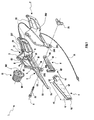
- Figure 1 is a partially exploded perspective view of an embodiment of the cutting device for branches and the like according to the present invention;
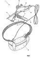
- Figure 2 is a perspective view of the cutting device of Fig. 1 in a fully assembled condition thereof;
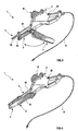
- Figure 3 shows the cutting device of Fig. 1 in a first operative configuration;
- Figure 4 shows the cutting device of Fig. 1 in a non operative configuration thereof; and
- Figure 5 shows the cutting device of Fig. 1 while in use in a second operative configuration thereof.
-
- With reference to Figure 1, a
cutting device 1 for branches and the like comprises a chassis member 2 and acutting tool 5 reciprocating with respect to the chassis member 2. Suchreciprocating cutting tool 5 is driven by means for driving that will be described in detail in the following. Thecutting device 1 is further provided with a protecting cover 4 of the reciprocatingcutting tool 5, movable with respect to the chassis 2. Thecutting device 1 further comprises a first arm 8 and a second arm 9, each rotatably connected at a first end thereof to the reciprocatingcutting tool 5 and at a second end thereof to the chassis member 2. As it will be illustrated hereinafter, such rotatable connections to the reciprocatingcutting tool 5 of the first and second arm, 8 and 9 respectively, are formed on distinct points, so as to support the reciprocatingcutting tool 5 itself with respect to the chassis member 2. - With further reference to Figure 1, in the present embodiment the chassis member 2 is made of two shells, and specifically a
first shell 201 and asecond shell 202, joined therebetween by means of traditional joining means. Suchfirst shell 201 andsecond shell 202 have afirst eyelet projection 203 and asecond eyelet projection 204, respectively. Such first andsecond eyelet projection pin 23. These first andsecond eyelet projection - The first arm 8, the second arm 9 and a
transmission system 3, that will hereinafter described in detail, are housed between the first and the second shell, 201 and 202 respectively, i.e. inside the chassis member 2. Moreover, suchfirst shell 201 andsecond shell 202 are shaped in such a manner that, once fixed one to the other, ahandgrip 20 is formed in the chassis member 2 (in this respect, see also Figure 2). - In this embodiment, the reciprocating
cutting tool 5 is a saw having a serration in a front and lower portion thereof. This saw will hereinafter be referred to as reciprocatingsaw 5. In order to better understand the operation steps of thecutting device 1, such reciprocatingsaw 5 is usefully described as comprising a non-serratedrear portion 51 and two serrated portions, i.e. amedian portion 52 and afront portion 53, the role of which will be made apparent hereinafter. However, it has to be pointed out that therear portion 51 of thereciprocating saw 5 is hidden to the user, as it is comprised between the aforesaidfirst shell 201 andsecond shell 202 of the chassis member 2. - Of course, the reciprocating cutting tool can also be made in forms differing from the above disclosed one.
- Further, in the present embodiment the means for driving comprise an
electric motor 10 of traditional type and well-known to a person skilled in the art, comprising astator 101 and arotor 102. In particular, thestator 101 is fixed to the chassis member 2, whereas therotor 102 moves of a continuous rotary motion and is connected to theabovementioned transmission system 3 according to steps them also well-known to a person skilled in the art. - The
electric motor 10 is operated by means of anoperating button 22. Of course,such operating button 22 will be susceptible of several specific embodiments. In particular, it could provide a system for blocking it in the operation position. Further, theoperating button 22 could be arranged internally to theaforesaid handgrip 20 instead of upperly thereto, as it is shown, e.g., in Figure 1, thereby further easing the powering up of thecutting device 1. Further, in alternative embodiments to the abovedisclosed onesuch operating button 22 could be replaced by other operating means, like e.g. one or more levers. - In this embodiment, the
transmission system 3 comprises acrank 12, connected to therotor 102 of theelectric motor 10, and arod 11, rotatably connected to thecrank 12 itself. During the operation of thecutting device 1, thecrank 12, driven by theelectric motor 10, rotates and transmits the motion to therod 11. - As already mentioned, said first arm 8 is rotatably connected at a first end thereof 81 onto the
rear portion 51 of thereciprocating saw 5. For the sake of simplicity, hereinafter such rotatable connection will be referred to as first articulation, it also indicated with thereference number 81. In the present embodiment the first arm 8 is also rotatably connected to therod 11 by means of thesame articulation 81. - The first arm 8 is also rotatably connected, at a
second end 82 thereof, to the chassis member 2, and particularly to thefirst shell 201 thereof. Analogously to what already said above, such rotatable connection will hereinafter be referred to as second articulation, and it also will be indicated with thereference number 82. The aforesaid second arm 9 is rotatably connected at afirst end 91 thereof onto therear portion 51 of thereciprocating saw 5. Such rotatable connection will hereinafter be referred to as third articulation, and it also will be indicated with thereference number 91. Lastly, the second arm 9 is rotatably connected at asecond end 92 thereof onto the chassis member 2, and in particular onto thefirst shell 201 of the latter. Such rotatable connection will hereinafter be referred to as fourth articulation, and it also will be indicated with thereference number 92. - As it is shown in Fig. 1, in order to implement the above disclosed rotatable connections the first ends 81 and 91 and the second ends 82 and 92, of the first and of the second arm 8 and 9 respectively, can be bent, in order to work as a pin element of the rotatable connections themselves. Further, such ends can be bushed in bronze bushings.
- The reciprocating, i.e. cutting, motion, of the reciprocating saw 5 will hereinafter be detailed. The
aforesaid rod 11, driven by thecrank 12, in turn drives the first arm 8 by means of thefirst articulation 81. The first arm 8, always by means of thefirst articulation 81, transmits the motion to thereciprocating saw 5. Thus, in the present embodiment the first arm 8 co-operates with thetransmission system 3 for transforming the continuous rotary motion of theelectric motor 10 into the reciprocating motion of thereciprocating saw 5. - It has now to be pointed out that the first arm 8, the second arm 9, the portion of the reciprocating saw 5 comprised between the
first articulation 81 and thethird articulation 91 and the portion of chassis member 2 comprised between thesecond articulation 82 and thefourth articulation 92 form an articulated quadrilateral mechanism. In particular, in the present embodiment such mechanism is a four-bar linkage. During the operation of thecutting device 1, thereciprocating saw 5 is actuated by the first arm 8, as already said above. The reciprocating saw 5, in turn, actuates the second arm 9 by means of thethird articulation 91. - Therefore, thanks to the presence of the first and of the second arm, 8 and 9 respectively, and to the fact that the respective rotatable connections thereof to the reciprocating saw 5 are distinct (first and third articulation, 81 and 91 respectively), the reciprocating saw 5 itself is supported with respect to the chassis 2 with no need for a guide or slideways, unlike in the devices of the known art. Hence, the reciprocating motion of the
reciprocating saw 5 is not hindered by the presence of debris deriving from branch cutting, as it cannot block the rotary motion of the first and second arm, 8 and 9 respectively. - Moreover, by virtue of the abovementioned articulated quadrilateral mechanism, the motion of the
reciprocating saw 5 does not follow a merely rectilinear path, as is the case for the cutting devices of the known art, although at all times the reciprocating saw 5 itself remains parallel to the same straight line. This provides a smooth cutting onto the branch external surface and a rounded cutting in-depth, apt to reduce friction. - The reciprocating motion of the
reciprocating saw 5 is guided by the above described articulated quadrilateral mechanism. In particular, the reciprocating saw 5 moves between a maximally forward position, in which the first and thethird articulation fourth articulation third articulation fourth articulation - Of course, several embodiments alternative to the above disclosed one are possible, both for the means for driving 10 and for the
transmission system 3 associated thereto. In particular, the above disclosedtransmission system 3 may be replaced by a stepping motor transmitting the motion directly to the first arm 8, at thesecond articulation 82. Alternatively, a linear motor, e.g. of the so-called «push-pull» type, could be used. In that case, the translational motion of the movable members of such motor could drive the reciprocating saw 5 by means of interposition of a connecting rod. Further, even when using a traditional rotary electric motor, thecrank 12 and therod 11 may be replaced by a different transmission system, based on the use of a cam mechanism. - The
cutting device 1 further comprises shielding means, globally indicated with 6, for shielding, during operation, themedian portion 52 of thereciprocating saw 5, according to steps that will be detailed with reference to Fig. 3. These shielding means 6 comprise, as it is shown in Fig. 1, abar 61 and afork 62, located at a front end of saidbar 61. Thefork 62 has a opening apt to allow the insertion of themedian portion 52 of thereciprocating saw 5. - The
bar 61 further has, at a rear end thereof, abar pin seat 63 for theabovementioned pin 23. Suchbar pin seat 63 permits the insertion of thepin 23 therethrough for hingedly connecting the shielding means 6 and the chassis member 2 therebetween. Such hinged connection between the shielding means 6 and the chassis member 2 takes place at theeyelet projections cutting device 1 thebar pin seat 63 of the shielding means 6 is arranged between theeyelet projections pin 23 can be sequentially inserted through thefirst eyelet projection 203, thebar pin seat 63 and thesecond eyelet projection 204. - By virtue of the above disclosed hinged connection, the shielding means 6 can be pivoted around an axis A of the
pin 23, in order to allow thecutting device 1 to assume various operative configurations, as it will hereinafter be illustrated with reference to Figs. 3, 4 and 5. - The pivoting excursion of the shielding means 6 is limited by first projecting
stoppers shells eyelet projections stoppers - As already mentioned, the
cutting device 1 further comprises the protecting cover 4, for covering theserration 54 of thereciprocating saw 5. The protecting cover 4 consists of a lengthwise opened sleeve member. Such sleeve member, which will hereinafter be indicated with the reference number 4, is provided with a first and a second larger, plane lateral wall, 41, 42 respectively, for receiving the reciprocating saw 5 therebetween in order to hide theserration 54 of the reciprocating saw 5 itself. Suchlateral walls frontal wall 45 and by a bottom wall, not shown in the figures. The longitudinal dimension of the sleeve member 4, indicated by anarrow 46 in Fig. 1, is such as to allow the insertion of the reciprocating saw 5 therein even when the latter is in the abovementioned maximally forward position. Moreover, the vertical dimension of such sleeve member 4 is larger than the vertical excursion of the motion of thereciprocating saw 5. This means that the sleeve member 4 can always cover theserration 54, regardless of the position of thereciprocating saw 5. - The transverse dimension of the sleeve member 4 is such as to permit the housing therein not merely of the
reciprocating saw 5, but of the abovedescribed shielding means 6 as well. - By virtue of its shape, the sleeve member 4 is apt to be inserted bottomwise on the
reciprocating saw 5. The aforesaid bottom wall prevents theserration 54 of the reciprocating saw 5 from coming out from the bottom of the sleeve member once this has been inserted on the reciprocating saw 5 itself. - The first and second
lateral wall sleeve pin seat 43 and a secondsleeve pin seat 44. Such first and secondsleeve pin seat pin 23 therethrough to hingedly connect the sleeve member 4 and the chassis member 2 therebetween. Such hinged connection takes place at the aforesaid first andsecond eyelet projection cutting device 1, the first and secondsleeve pin seat eyelet projections bar pin seat 63 of the shielding means 6 are comprised therebetween. Then, thepin 23 is sequentially inserted through the firstsleeve pin seat 43 of the sleeve member 4, thefirst eyelet projection 203 of the chassis member 2, thebar pin seat 63 of the shielding means 6, thesecond eyelet projection 204 of the chassis member 2, and the secondsleeve pin seat 44 of the sleeve member 4. Then thepin 23 is blocked with the chassis member 2 by means of a blockingmember 24 of a traditional type, sketched in Fig. 1. - Fig. 2 can be referred to in order to better understand the mutual arrangement of the sleeve member 4 and of the shielding means 6 when the
cutting device 1 is fully assembled. - By virtue of the above described hinged connection, the sleeve member 4 can be pivoted about the axis A of the
pin 23, in order to make the cutting device assume a non operative or a operative configuration, as it will be described in detail with reference to Figs. 3 and 4. - The rotation of the sleeve member 4 is limited by second projecting stoppers (not shown in the figures), arranged near the sleeve pin seats 43 and 44. Such second projecting stoppers are apt to abut the chassis member 2, and their role, together with that of the first projecting stoppers mentioned with reference to the shielding means 6, will be made apparent with reference to Fig. 4.
- In an alternative embodiment, the protecting cover may be separate from the remaining part of the
cutting device 1. In that case, the protecting cover could be fixed to the chassis member 2 only at the moment of its insertion around thereciprocating saw 5, e.g. with fixing means of a bayonet type. - With reference to Fig. 2, the
electric motor 10 of thecutting device 1 can be power supplied through acable 21.Such cable 21 can connect theelectric motor 10 to a portable battery. Advantageously, such battery will be rechargeable and carried into a pouch M. - It will be appreciated that this transport and power supply modality of the
cutting device 1 emphasises the portability thereof. In particular, as it is shown in Fig. 5, a user can easily use thecutting device 1 for branches and the like by gripping it by thehandgrip 20, and move around carrying the relative power supply source in the pouch M, absolutely without being hampered in his/her movements. - Of course, other power sources could be provided as well. For instance, the
electric motor 10 could be power supplied by connecting thecable 21 to the battery of a car, tractor or any other agricultural vehicle. - The various possible configurations of the
cutting device 1 will hereinafter be described in detail. - Fig. 4 shows the
cutting device 1 in a non operative configuration. In such configuration theelectric motor 10 is usually inactive, and therefore thereciprocating saw 5 is still. Moreover, the shielding means 6 were pivoted about the axis A of Fig. 1 to displace them below thereciprocating saw 5, so that themedian portion 52 of the reciprocating saw 5 itself is inserted into the opening of thefork 62. Analogously, also the sleeve member 4 was pivoted about the axis A, externally to the shielding means 6. This pivoting of the sleeve member 4 permits the insertion of the reciprocating saw 5 therein. Thus, the cutting part of thereciprocating saw 5, i.e. theserration 54, is made inaccessible to the user. - It has to be pointed out that the transverse dimension of the sleeve member 4 and the mutual arrangement of the two hinged connections sleeve member 4 - chassis member 2 and shielding means 6 - chassis member 2 permit also to the shielding means 6 to be housed internally to the sleeve member 4, as it is shown in Fig. 4. This makes the
cutting device 1 extremely compact and of little bulkiness in the non operative configuration thereof. - It will therefore be appreciated that the sleeve member 4 performs a double protective function. Firstly, it avoids a possible wounding of the user with the
serration 54 of thereciprocating saw 5. Further, the sleeve member protects the reciprocating saw 5 from the atmospheric conditions and from mechanical stresses such as impacts and the like. - A further important advantage of the
cutting device 1 is that the sleeve member 4 performs this double protective function even when thereciprocating saw 5 is erroneously started while thecutting device 1 is in its non operative configuration. This significant advantage of thecutting device 1 is provided by two factors. Firstly, as mentioned above, thelongitudinal dimension 46 and the vertical dimension of the sleeve member 4 provide the covering of theserration 54 regardless of the position of thereciprocating saw 5. This ensures that the latter does not come out of the sleeve member 4 even when started, or that the sleeve member 4 itself interferes with the motion thereof. Hence, the user is anyhow protected by the sleeve member 4, regardless of the fact that thereciprocating saw 5 is still or performing a cutting motion. Further, the first projectingstoppers reciprocating saw 5. The second projecting stoppers of the sleeve member 4 perform an analogous function with respect to the pivoting of the sleeve member 4 itself. Therefore, there is no risk of interference between thereciprocating saw 5 and the other components of thecutting device 1. This further protects the user and avoids the risk of damages to the reciprocating saw 5 as well as to thecutting device 1 as a whole. - Hereinafter, two possible operative configurations of the
cutting device 1 will be described. - With reference to Fig. 3, in order to cut branches and the like, the user first of all releases the reciprocating saw 5 from the sleeve member 4. This can easily be carried out by pivoting the sleeve member 4 counterclockwise of about 180 degrees, in order to have it abutting under the chassis member 2. Then, the user operates the
cutting device 1 by means of theoperating button 22. In this way, thecutting device 1 assumes a first operative configuration, in which themedian portion 52 of thereciprocating saw 5 is located into theopening fork 62 of the shielding means 6. Therefore, such sawmedian portion 52 is shielded, i.e. the shielding means 6 avoid its coming into contact with the branches to be cut. Thus, themedian portion 52 of thereciprocating saw 5 does not cooperate to the cutting, although it is obviously driven by theelectric motor 10. This first operative configuration proves useful for the user in cutting small branches. - Instead, referring also to Fig. 5, in order to cut larger branches, the user will need to use the entire useful length of the
reciprocating saw 5, i.e. both the serrated saw median andfront portion cutting device 1 by means of theoperating button 22, the user pivots the shielding means 6 counterclockwise for about 180 degrees, in order to make them release themedian portion 52 of thereciprocating saw 5 and abut under the chassis member 2, within the sleeve member 4. In this way, thedevice 1 assumes a second operative configuration, shown in Fig. 5. It has to be pointed out that, in this second operative configuration, the position of the sleeve member 4 and of the shielding means 6 under the chassis member 2 provides that they do not even slightly hamper neither the user's motions, nor the cutting. - It will be appreciated from the what disclosed above that the shielding means makes the cutting device extremely versatile. In particular, they allow the use of a single cutting device for cutting large, as well as middle and small branches. This provides a significant advantage with respect to the cutting devices of the known art, which need to be used concomitantly to shears or scissors for the cutting of small branches.
- The cutting device according to the invention, by virtue of the hereto mentioned properties, is suitable for the pruning of a wide range of trees, and particularly suitable for the pruning of olive trees.
- Of course, the shielding means are susceptible of several embodiments alternative to those described up to now. For instance, it may comprise a retractable member sliding onto a slideway or onto a guide blocked with the chassis member. In this way, the length of the saw portion to be shielded might be adjustable as well.
- The present invention has hereto been disclosed with reference to preferred embodiments thereof. It is understood that there may be other embodiments thereof, all however comprised within the protective scope of the annexed claims.
Claims (21)
- A cutting device (1) for branches and the like, comprising:characterised in that it also comprises a movable protecting cover (4) for covering said reciprocating cutting tool (5), and wherein said bar (61) is provided with a fork (62) at one end thereof, said fork (62) having an opening for permitting a releasable insertion of said median portion (52) of said reciprocating cutting tool (5).a chassis member (2),a cutting tool (5) reciprocating with respect to said chassis member (2),means for driving (10) said reciprocating cutting tool (5),a first arm (8) and a second arm (9), each of said first (8) and second (9) arm being rotatably connected at a first end thereof (81, 91) to said reciprocating cutting tool (5), and at a second end thereof (82, 92) to said chassis member (2), wherein said rotatable connections (81, 91) of said first (8) and second arm (9) to said reciprocating cutting tool (5) are formed on distinct points for supporting said reciprocating cutting tool (5) with respect to said chassis member (2), and shielding means (6) apt to shield a median portion (52) of said reciprocating cutting tool (5), so that said median portion (52) does not cooperate to the cutting, wherein said shielding means (6) comprises a bar (61)
- The device (1) according to claim 1, wherein said shielding means (6) is hingedly connected to said chassis member (2) so that said device (1) assumes a first operative configuration, wherein said shielding means (6) are pivoted below said reciprocating cutting tool (5) and said median portion (52) of said reciprocating cutting tool (5) is inserted in said opening of said fork (62), and a second operative configuration, wherein said shielding means (6) abut said chassis member (2) and said median portion (52) of said cutting tool (5) is free and co-operates to the cutting.
- The device (1) according to the preceding claim, wherein said bar (61) has, at one end thereof opposed to said fork (62), a bar pin seat (63) for making said hinged connection of said shielding means (6) to said chassis member (2).
- The device (1) according to claim 2 or 3, wherein said chassis member (2) comprises first projecting stoppers (205, 206), apt to abut said shielding means (6) when said device (1) assumes said first operative configuration.
- The device (1) according to any of the preceding claims, wherein said first arm (8), said second arm (9), said reciprocating cutting tool (5) and said chassis member (2) make an articulated quadrilateral mechanism.
- The device (1) according to the preceding claim, wherein said first arm (8), said second arm (9), said reciprocating cutting tool (5) and said chassis member (2) make a four-bar linkage mechanism.
- The device (1) according to any of the preceding claims, wherein said means for driving comprise a rotary electric motor (10).
- The device (1) according to the preceding claim, comprising a transmission system (3) for transforming the rotary motion of said electric motor (10) into the reciprocating motion of said reciprocating cutting tool (5), said transmission system (3) comprising a crank (12), connected to said electric motor (10), and a rod (11), rotatably connected to said crank (12).
- The device (1) according to the preceding claim, wherein said first arm (8) is rotatably connected, at said first end (81), to said rod (11), for transmitting the rotary motion of said electric motor (10) to said reciprocating cutting tool (5).
- The device (1) according to any of the preceding claims, wherein said protecting cover (4) is hingedly connected to said chassis member (2), so that said device (1) assumes a non operative configuration, wherein said protecting cover (4) is pivoted for covering said reciprocating cutting tool (5), and an operative configuration, wherein said protecting cover (4) abuts said chassis member (2).
- The device (1) according to any of the preceding claims, wherein said protecting cover comprises a sleeve member (4) lengthwise opened for receiving said reciprocating cutting tool (5), the dimensions of said sleeve member (4) being such as to permit the insertion therein of said reciprocating cutting tool (5) for any position assumed by said reciprocating cutting tool (5) in the reciprocating motion thereof.
- The device (1) according to the preceding claim, wherein and said sleeve member (4) has at least one sleeve pin seat (43, 44) for making a hinged connection of said sleeve member (4) to said chassis member (2), so that said device (1) assumes a non operative configuration, wherein said sleeve member (4) is pivoted for covering said reciprocating cutting tool (5), and a operative configuration, wherein said sleeve member (4) abuts said chassis member (2).
- The device (1) according to the preceding claim, wherein said sleeve member (4) has a first (43) and a second (44) sleeve pin seat, made on respective lateral walls (41, 42) of said sleeve member (4).
- The device (1) according to claim 12 or 13, wherein said sleeve member (4) comprises, near said at least one sleeve pin seat (43, 44), second projecting stoppers, apt to abut said chassis member (2) when said device (1) assumes said operative configuration.
- The device (1) according to claim 10, wherein said chassis member (2) comprises a first (203) and a second (204) eyelet projection, to make said hinged connection of said chassis member (2) to said protecting cover (4).
- The device (1) according to any one of claims 2 to 4, wherein said chassis member (2) comprises a first (203) and a second (204) eyelet projection, to make said hinged connection of said chassis member (2) to said shielding means (6).
- The device (1) according to any one of the preceding claims, wherein said protecting cover (4) and said shielding means (6) are hingedly connected to said chassis member (2) about a same axis of rotation (A).
- The device (1) according to any of the preceding claims, wherein said reciprocating cutting tool comprises a reciprocating saw (5), having in a front and lower portion (52, 53) thereof a serration (54), said reciprocating saw (5) being movable with respect to said chassis member (2) between a maximally forward position and a minimally forward position.
- The device (1) according to the preceding claim, wherein said rotatable connections (81, 91) of said first (8) and second (9) arm with said reciprocating cutting tool are made at a non serrated portion (51) of said reciprocating saw (5).
- The device (1) according to any of the preceding claims, wherein said chassis member (2) comprises a handgrip (20), formed thereon.
- A cutting kit for branches and the like, comprising a cutting device (1) for branches and the like according to any one of the preceding claims, a battery for power supplying said means for driving (10) of said device (1) and a pouch (M) for housing said battery.
Applications Claiming Priority (3)
| Application Number | Priority Date | Filing Date | Title |
|---|---|---|---|
| ITFG990000 | 1999-02-22 | ||
| IT1999FG000003A ITFG990003A1 (en) | 1999-02-22 | 1999-02-22 | ALTERNATIVE ELECTRIC SAW, WITH TOOTHED BLADE SUPPORTED BY PENDULUM ARMS, WITH BLADE COVER SHEATH AND REVOLVING PINK COVER SUPPORT |
| ITFG990003 | 1999-02-22 |
Publications (3)
| Publication Number | Publication Date |
|---|---|
| EP1031395A2 EP1031395A2 (en) | 2000-08-30 |
| EP1031395A3 EP1031395A3 (en) | 2002-11-20 |
| EP1031395B1 true EP1031395B1 (en) | 2004-11-17 |
Family
ID=11349402
Family Applications (1)
| Application Number | Title | Priority Date | Filing Date |
|---|---|---|---|
| EP99830786A Expired - Lifetime EP1031395B1 (en) | 1999-02-22 | 1999-12-21 | Reciprocating saw for cutting branches |
Country Status (6)
| Country | Link |
|---|---|
| EP (1) | EP1031395B1 (en) |
| AT (1) | ATE282500T1 (en) |
| DE (1) | DE69921959T2 (en) |
| ES (1) | ES2233013T3 (en) |
| IT (1) | ITFG990003A1 (en) |
| PT (1) | PT1031395E (en) |
Families Citing this family (8)
| Publication number | Priority date | Publication date | Assignee | Title |
|---|---|---|---|---|
| GB2416329B (en) * | 2002-10-01 | 2007-06-20 | Milwaukee Electric Tool Corp | Saw |
| US20040060178A1 (en) * | 2002-10-01 | 2004-04-01 | Mark Willer | Circular saw |
| ITRM20030374A1 (en) * | 2003-07-30 | 2005-01-31 | Remo Francesco Cecchi | CUTTING DEVICE FOR BRANCHES AND THE LIKE. |
| EP1747711A1 (en) * | 2005-07-26 | 2007-01-31 | Daniela Cecchi | Cutting device |
| US7814666B2 (en) * | 2007-02-13 | 2010-10-19 | Robert Bosch Gmbh | Linkage drive mechanism for a reciprocating tool |
| US8549762B2 (en) | 2007-02-13 | 2013-10-08 | Robert Bosch Gmbh | Linkage drive mechanism for a reciprocating tool |
| DE102008041095A1 (en) * | 2008-08-07 | 2010-02-11 | Robert Bosch Gmbh | Hand tool |
| CN102284744B (en) * | 2010-06-18 | 2015-07-01 | 苏州宝时得电动工具有限公司 | Reciprocating saw |
Family Cites Families (10)
| Publication number | Priority date | Publication date | Assignee | Title |
|---|---|---|---|---|
| DE77566C (en) * | E. benninghoven, Höhscheid b. Solingen | Handle for saws, knives and the like, which also serves as a shoulder for the cutting edge | ||
| US1492721A (en) * | 1922-04-17 | 1924-05-06 | Leon J Barrett | Extension pruning saw |
| FR1139951A (en) * | 1955-12-08 | 1957-07-09 | Oscillating sawing machine | |
| US3834019A (en) * | 1972-11-22 | 1974-09-10 | Maremont Corp | Apparatus for cutting exhaust system tubes |
| US4280276A (en) * | 1980-01-18 | 1981-07-28 | The Toro Company | Reciprocating cutter |
| US4294012A (en) * | 1980-03-25 | 1981-10-13 | Lanz Donald D | Chain saw anti-pinch guard arm |
| BE884632A (en) * | 1980-08-05 | 1980-12-01 | Durieux Jules | MOTORIZED SAW PRUNER. |
| DE3643558A1 (en) * | 1986-12-19 | 1988-07-07 | Wolf Geraete Gmbh | ELECTRIC MOTOR DRIVE SYSTEM |
| DE3722542A1 (en) * | 1987-07-08 | 1989-01-19 | Reinhard Freund Maschinenfabri | JIGSAW |
| IT1298236B1 (en) * | 1998-02-13 | 1999-12-20 | Bruno Pianu | PORTABLE SAW DECORTING MACHINE, WITH ELECTRONIC SENSITIVE FOOT, ESPECIALLY FOR CORK |
-
1999
- 1999-02-22 IT IT1999FG000003A patent/ITFG990003A1/en unknown
- 1999-12-21 DE DE69921959T patent/DE69921959T2/en not_active Expired - Fee Related
- 1999-12-21 ES ES99830786T patent/ES2233013T3/en not_active Expired - Lifetime
- 1999-12-21 PT PT99830786T patent/PT1031395E/en unknown
- 1999-12-21 AT AT99830786T patent/ATE282500T1/en not_active IP Right Cessation
- 1999-12-21 EP EP99830786A patent/EP1031395B1/en not_active Expired - Lifetime
Also Published As
| Publication number | Publication date |
|---|---|
| DE69921959T2 (en) | 2005-11-03 |
| EP1031395A2 (en) | 2000-08-30 |
| ATE282500T1 (en) | 2004-12-15 |
| PT1031395E (en) | 2005-03-31 |
| EP1031395A3 (en) | 2002-11-20 |
| ES2233013T3 (en) | 2005-06-01 |
| ITFG990003A1 (en) | 2000-08-22 |
| DE69921959D1 (en) | 2004-12-23 |
Similar Documents
| Publication | Publication Date | Title |
|---|---|---|
| US9032630B2 (en) | Vegetation trimmer | |
| US6190184B1 (en) | Connector for electric appliances | |
| US11565432B2 (en) | Utility knife | |
| TWI471087B (en) | Power tool | |
| EP1031395A2 (en) | Reciprocating saw for cutting branches | |
| US7698881B2 (en) | Walk-behind mower control system and method | |
| CN101500723A (en) | Hand-held, portable, battery-powered hydraulic tool | |
| US5509836A (en) | Outboard motor | |
| CN100381038C (en) | Pivoting handle assembly for power tool | |
| CN116267177A (en) | Power Tools and Folding Rod Assemblies | |
| JP7827564B2 (en) | Cable cutter and its ring attachment | |
| EP0933836A3 (en) | Connector with coupling assist mechanism | |
| JP3183504B2 (en) | Branch cutting tool and reciprocating branch cutting machine | |
| JP4615850B2 (en) | Power working machine | |
| US20150150192A1 (en) | Folding Arrangement for a Handle Assembly of Walk-Behind Power Tool, a Handle Assembly and a Walk-Behind Power Tool Comprising Such an Arrangement | |
| EP0981945A3 (en) | Safety lock mechanism for a lever switch | |
| JP2543355B2 (en) | Electric saw | |
| EP1502718B1 (en) | Device for cutting branches and the like | |
| JP4606244B2 (en) | Brush cutter | |
| JP3960892B2 (en) | Variable angle mechanism of working device in working machine | |
| CN219902239U (en) | Cable cutting device | |
| EP4663358A1 (en) | Cutting device | |
| CN211671498U (en) | Working machine | |
| KR20210013856A (en) | Modular Jack Connecting Tool | |
| JP2019171660A (en) | Chain saw |
Legal Events
| Date | Code | Title | Description |
|---|---|---|---|
| PUAI | Public reference made under article 153(3) epc to a published international application that has entered the european phase |
Free format text: ORIGINAL CODE: 0009012 |
|
| AK | Designated contracting states |
Kind code of ref document: A2 Designated state(s): AT BE CH CY DE DK ES FI FR GB GR IE IT LI LU MC NL PT SE |
|
| AX | Request for extension of the european patent |
Free format text: AL;LT;LV;MK;RO;SI |
|
| K1C1 | Correction of patent application (title page) published |
Effective date: 20000830 |
|
| PUAL | Search report despatched |
Free format text: ORIGINAL CODE: 0009013 |
|
| AK | Designated contracting states |
Kind code of ref document: A3 Designated state(s): AT BE CH CY DE DK ES FI FR GB GR IE IT LI LU MC NL PT SE |
|
| AX | Request for extension of the european patent |
Free format text: AL;LT;LV;MK;RO;SI |
|
| 17P | Request for examination filed |
Effective date: 20030325 |
|
| 17Q | First examination report despatched |
Effective date: 20030602 |
|
| AKX | Designation fees paid |
Designated state(s): AT BE CH CY DE DK ES FI FR GB GR IE IT LI LU MC NL PT SE |
|
| GRAP | Despatch of communication of intention to grant a patent |
Free format text: ORIGINAL CODE: EPIDOSNIGR1 |
|
| GRAS | Grant fee paid |
Free format text: ORIGINAL CODE: EPIDOSNIGR3 |
|
| GRAA | (expected) grant |
Free format text: ORIGINAL CODE: 0009210 |
|
| AK | Designated contracting states |
Kind code of ref document: B1 Designated state(s): AT BE CH CY DE DK ES FI FR GB GR IE IT LI LU MC NL PT SE |
|
| PG25 | Lapsed in a contracting state [announced via postgrant information from national office to epo] |
Ref country code: SE Free format text: LAPSE BECAUSE OF FAILURE TO SUBMIT A TRANSLATION OF THE DESCRIPTION OR TO PAY THE FEE WITHIN THE PRESCRIBED TIME-LIMIT Effective date: 20041117 Ref country code: NL Free format text: LAPSE BECAUSE OF FAILURE TO SUBMIT A TRANSLATION OF THE DESCRIPTION OR TO PAY THE FEE WITHIN THE PRESCRIBED TIME-LIMIT Effective date: 20041117 Ref country code: FI Free format text: LAPSE BECAUSE OF FAILURE TO SUBMIT A TRANSLATION OF THE DESCRIPTION OR TO PAY THE FEE WITHIN THE PRESCRIBED TIME-LIMIT Effective date: 20041117 Ref country code: CY Free format text: LAPSE BECAUSE OF FAILURE TO SUBMIT A TRANSLATION OF THE DESCRIPTION OR TO PAY THE FEE WITHIN THE PRESCRIBED TIME-LIMIT Effective date: 20041117 |
|
| REG | Reference to a national code |
Ref country code: GB Ref legal event code: FG4D |
|
| REG | Reference to a national code |
Ref country code: CH Ref legal event code: EP |
|
| REG | Reference to a national code |
Ref country code: IE Ref legal event code: FG4D |
|
| PG25 | Lapsed in a contracting state [announced via postgrant information from national office to epo] |
Ref country code: IE Free format text: LAPSE BECAUSE OF NON-PAYMENT OF DUE FEES Effective date: 20041221 |
|
| REF | Corresponds to: |
Ref document number: 69921959 Country of ref document: DE Date of ref document: 20041223 Kind code of ref document: P |
|
| PG25 | Lapsed in a contracting state [announced via postgrant information from national office to epo] |
Ref country code: MC Free format text: LAPSE BECAUSE OF NON-PAYMENT OF DUE FEES Effective date: 20041231 |
|
| PG25 | Lapsed in a contracting state [announced via postgrant information from national office to epo] |
Ref country code: LU Free format text: LAPSE BECAUSE OF NON-PAYMENT OF DUE FEES Effective date: 20050117 |
|
| PG25 | Lapsed in a contracting state [announced via postgrant information from national office to epo] |
Ref country code: DK Free format text: LAPSE BECAUSE OF FAILURE TO SUBMIT A TRANSLATION OF THE DESCRIPTION OR TO PAY THE FEE WITHIN THE PRESCRIBED TIME-LIMIT Effective date: 20050217 |
|
| REG | Reference to a national code |
Ref country code: CH Ref legal event code: NV Representative=s name: PATENTANWAELTE SCHAAD, BALASS, MENZL & PARTNER AG |
|
| REG | Reference to a national code |
Ref country code: GR Ref legal event code: EP Ref document number: 20050400310 Country of ref document: GR |
|
| REG | Reference to a national code |
Ref country code: PT Ref legal event code: SC4A Free format text: AVAILABILITY OF NATIONAL TRANSLATION Effective date: 20050203 |
|
| NLV1 | Nl: lapsed or annulled due to failure to fulfill the requirements of art. 29p and 29m of the patents act | ||
| REG | Reference to a national code |
Ref country code: ES Ref legal event code: FG2A Ref document number: 2233013 Country of ref document: ES Kind code of ref document: T3 |
|
| REG | Reference to a national code |
Ref country code: IE Ref legal event code: MM4A |
|
| PLBE | No opposition filed within time limit |
Free format text: ORIGINAL CODE: 0009261 |
|
| STAA | Information on the status of an ep patent application or granted ep patent |
Free format text: STATUS: NO OPPOSITION FILED WITHIN TIME LIMIT |
|
| ET | Fr: translation filed | ||
| 26N | No opposition filed |
Effective date: 20050818 |
|
| PGFP | Annual fee paid to national office [announced via postgrant information from national office to epo] |
Ref country code: CH Payment date: 20081215 Year of fee payment: 10 |
|
| PGFP | Annual fee paid to national office [announced via postgrant information from national office to epo] |
Ref country code: PT Payment date: 20081202 Year of fee payment: 10 Ref country code: ES Payment date: 20081217 Year of fee payment: 10 Ref country code: AT Payment date: 20081215 Year of fee payment: 10 |
|
| PGFP | Annual fee paid to national office [announced via postgrant information from national office to epo] |
Ref country code: FR Payment date: 20081212 Year of fee payment: 10 |
|
| PGFP | Annual fee paid to national office [announced via postgrant information from national office to epo] |
Ref country code: DE Payment date: 20081219 Year of fee payment: 10 |
|
| PGFP | Annual fee paid to national office [announced via postgrant information from national office to epo] |
Ref country code: GR Payment date: 20081218 Year of fee payment: 10 Ref country code: GB Payment date: 20081216 Year of fee payment: 10 |
|
| PGFP | Annual fee paid to national office [announced via postgrant information from national office to epo] |
Ref country code: BE Payment date: 20090130 Year of fee payment: 10 |
|
| PGFP | Annual fee paid to national office [announced via postgrant information from national office to epo] |
Ref country code: IT Payment date: 20091023 Year of fee payment: 11 |
|
| REG | Reference to a national code |
Ref country code: PT Ref legal event code: MM4A Free format text: LAPSE DUE TO NON-PAYMENT OF FEES Effective date: 20100621 |
|
| BERE | Be: lapsed |
Owner name: *CECCHI DANIELA Effective date: 20091231 Owner name: *CECCHI MARCO Effective date: 20091231 |
|
| PG25 | Lapsed in a contracting state [announced via postgrant information from national office to epo] |
Ref country code: PT Free format text: LAPSE BECAUSE OF NON-PAYMENT OF DUE FEES Effective date: 20100621 |
|
| REG | Reference to a national code |
Ref country code: CH Ref legal event code: PL |
|
| GBPC | Gb: european patent ceased through non-payment of renewal fee |
Effective date: 20091221 |
|
| PG25 | Lapsed in a contracting state [announced via postgrant information from national office to epo] |
Ref country code: AT Free format text: LAPSE BECAUSE OF NON-PAYMENT OF DUE FEES Effective date: 20091221 |
|
| REG | Reference to a national code |
Ref country code: FR Ref legal event code: ST Effective date: 20100831 |
|
| PG25 | Lapsed in a contracting state [announced via postgrant information from national office to epo] |
Ref country code: LI Free format text: LAPSE BECAUSE OF NON-PAYMENT OF DUE FEES Effective date: 20091231 Ref country code: FR Free format text: LAPSE BECAUSE OF NON-PAYMENT OF DUE FEES Effective date: 20091231 Ref country code: CH Free format text: LAPSE BECAUSE OF NON-PAYMENT OF DUE FEES Effective date: 20091231 Ref country code: BE Free format text: LAPSE BECAUSE OF NON-PAYMENT OF DUE FEES Effective date: 20091231 |
|
| PG25 | Lapsed in a contracting state [announced via postgrant information from national office to epo] |
Ref country code: DE Free format text: LAPSE BECAUSE OF NON-PAYMENT OF DUE FEES Effective date: 20100701 |
|
| PG25 | Lapsed in a contracting state [announced via postgrant information from national office to epo] |
Ref country code: GB Free format text: LAPSE BECAUSE OF NON-PAYMENT OF DUE FEES Effective date: 20091221 |
|
| REG | Reference to a national code |
Ref country code: ES Ref legal event code: FD2A Effective date: 20110309 |
|
| PG25 | Lapsed in a contracting state [announced via postgrant information from national office to epo] |
Ref country code: ES Free format text: LAPSE BECAUSE OF NON-PAYMENT OF DUE FEES Effective date: 20110308 |
|
| PG25 | Lapsed in a contracting state [announced via postgrant information from national office to epo] |
Ref country code: ES Free format text: LAPSE BECAUSE OF NON-PAYMENT OF DUE FEES Effective date: 20091222 |
|
| PG25 | Lapsed in a contracting state [announced via postgrant information from national office to epo] |
Ref country code: IT Free format text: LAPSE BECAUSE OF NON-PAYMENT OF DUE FEES Effective date: 20101221 |