EP1031264A1 - A machine to be coupled to a tractor or the like vehicle. - Google Patents
A machine to be coupled to a tractor or the like vehicle. Download PDFInfo
- Publication number
- EP1031264A1 EP1031264A1 EP00200175A EP00200175A EP1031264A1 EP 1031264 A1 EP1031264 A1 EP 1031264A1 EP 00200175 A EP00200175 A EP 00200175A EP 00200175 A EP00200175 A EP 00200175A EP 1031264 A1 EP1031264 A1 EP 1031264A1
- Authority
- EP
- European Patent Office
- Prior art keywords
- boom
- boom part
- respect
- coupled
- tractor
- Prior art date
- Legal status (The legal status is an assumption and is not a legal conclusion. Google has not performed a legal analysis and makes no representation as to the accuracy of the status listed.)
- Granted
Links
Images

Classifications
-
- A—HUMAN NECESSITIES
- A01—AGRICULTURE; FORESTRY; ANIMAL HUSBANDRY; HUNTING; TRAPPING; FISHING
- A01B—SOIL WORKING IN AGRICULTURE OR FORESTRY; PARTS, DETAILS, OR ACCESSORIES OF AGRICULTURAL MACHINES OR IMPLEMENTS, IN GENERAL
- A01B73/00—Means or arrangements to facilitate transportation of agricultural machines or implements, e.g. folding frames to reduce overall width
-
- E—FIXED CONSTRUCTIONS
- E02—HYDRAULIC ENGINEERING; FOUNDATIONS; SOIL SHIFTING
- E02F—DREDGING; SOIL-SHIFTING
- E02F3/00—Dredgers; Soil-shifting machines
- E02F3/04—Dredgers; Soil-shifting machines mechanically-driven
- E02F3/28—Dredgers; Soil-shifting machines mechanically-driven with digging tools mounted on a dipper- or bucket-arm, i.e. there is either one arm or a pair of arms, e.g. dippers, buckets
- E02F3/30—Dredgers; Soil-shifting machines mechanically-driven with digging tools mounted on a dipper- or bucket-arm, i.e. there is either one arm or a pair of arms, e.g. dippers, buckets with a dipper-arm pivoted on a cantilever beam, i.e. boom
- E02F3/301—Dredgers; Soil-shifting machines mechanically-driven with digging tools mounted on a dipper- or bucket-arm, i.e. there is either one arm or a pair of arms, e.g. dippers, buckets with a dipper-arm pivoted on a cantilever beam, i.e. boom with more than two arms (boom included), e.g. two-part boom with additional dipper-arm
Definitions
- the invention relates to a machine to be coupled to a tractor or the like vehicle, comprising an articulated boom which includes at least two boom parts which are adjustable with respect to each other about a horizontal pivot axis, whilst the boom is coupled with one end to a mounting bracket to be attached to the tractor or the like, in such a manner that the boom is pivotable about a vertical pivot axis as well as about a horizontal pivot axis with respect to the mounting bracket, whilst an implement is coupled to the other free end of the boom, which implement is adjustable with respect to the boom about a pivot axis which extends transversely to the longitudinal axis of the boom.
- a machine of this kind is known from US-A-5,755,075.
- the implements which are used with such a machine are for example used for ditch and roadside maintenance, wherein the implement is a cutting device or a cutter basket of comparatively great length, which implement can extend transversely to the boom during operation.
- the boom In order to have a large working range, for example when clearing ditches, mowing slopes and the like, also the boom has a comparatively great length.
- a problem that presents itself thereby is the transport of such a combination of a tractor and a machine coupled thereto by road.
- the dimensions of the machine, in particular the length of the boom and/or of the implement may be such that such a combination no longer falls within the legal measurements for vehicles that travel on public roads.
- the object of the invention is to obtain a machine of the above kind, wherein the drawbacks of the machines that have been used so far can be alleviated or eliminated.
- this objective can be accomplished in that the boom of the machine to be coupled to one side of the tractor or the like comprises three parts which are pivotable about horizontal pivot axes with respect to each other, wherein the boom part which joins the boom part which is connected to the mounting bracket is pivotable with respect to said latter boom part between two positions on either side of said boom part.
- a part of the boom to which the implement is coupled is adjustable with respect to the other part of the boom about a pivot axis which crosses the horizontal pivot axis between the boom parts.
- the part of the boom that supports the implement can thereby be moved to a position in which said boom part extends transversely to the longitudinal direction of the tractor, seen in top plan view of the tractor or the like, thus enabling an even further reduction of the dimensions of parts of the machine that may project beyond the circumference of the tractor.
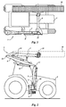
- Figure 1 shows a tractor 1, to one side of which a machine 3 is coupled by means of a mounting bracket 2.
- Machine 3 comprises a boom, which is built up of four boom parts 5 - 8.
- Boom part 5 is pivotally connected to the mounting bracket 2 at one end by means of a horizontally extending pivot pin 9.
- a setting cylinder 10 which is known per se is mounted between mounting bracket 2 and the end of boom part 5 remote from pivot pin 9 for pivoting boom part 5 and the further boom parts 6 - 8 connected thereto, which setting cylinder is positioned under boom part 5 in the operative position which is shown in Figure 1.
- Boom part 6 is connected to the end of boom part 5 remote from pivot pin 9 by means of a pivot pin 11 which extends parallel to pivot pin 9.
- a setting cylinder 12 extending above boom part 6, seen in Figure 1, is mounted between the two boom parts 5 and 6 for pivoting boom part 6 and the boom parts 7 and 8 connected thereto with respect to boom part 5.
- boom part 7 is connected to the end of boom part 6 remote from boom part 5 by means of a pivot pin 13 extending parallel to pivot pins 9 and 11.
- a setting cylinder 14 extending under boom part 6, seen in Figure 1, is mounted between boom part 6 and boom part 7 for pivoting boom part 7 and the boom part 8 connected thereto.
- the two boom parts 7 and 8 are pivotally interconnected by means of a pivot pin 15 extending perpendicularly to the longitudinal direction of said two boom parts 7 and 8, which pivot pin 15 crosses the pivot pins 9, 11 and 13 perpendicularly.
- Boom part 8 can be pivoted about pivot pin 15 with respect to boom part 7 by means of a setting cylinder 8' ( Figure 3), and be locked, by means not shown, against pivoting movement about pivot pin 15 in the position which is shown in Figure 1, in which the two boom parts 7 and 8 are in line, and in the position which is shown in Figures 2 and 3, in which position boom part 8 extends perpendicularly to boom part 7.
- a connecting piece 16 is mounted on the free end of boom part 8, which connecting piece 16 is pivotable about a pivot pin 18 by means of a setting cylinder 17 mounted between said boom part 8 and connecting piece 16.
- the setting cylinder 17 In the operative position of the combination of tractor 1 and machine 3 which is shown in Figure 1, the setting cylinder 17 is positioned above boom part 8, whilst pivot pin 18 extends parallel to pivot pins 9, 11 and 13.
- An implement 20 is coupled to said connecting piece 16 by means of a pivot pin 19 which crosses pivot pin 18 perpendicularly.
- said implement 20 is an elongated cutter basket which is known per se, which is used for clearing ditches and the like.
- the cutter basket comprises a cutter bar extending in the longitudinal direction of the cutter basket, by means of which plants present in the ditch or the like can be cut and subsequently received in the basket.
- the cutter basket comprises a cutter bar extending in the longitudinal direction of the cutter basket, by means of which plants present in the ditch or the like can be cut and subsequently received in the basket.
- cutter basket can be moved along the boundaries of a ditch or drain 21 or the like during operation by manipulating the various setting cylinders 10, 12, 14 and/or 17.
- the machine 3 can be pivoted for transport with respect to tractor 1 and with respect to the mounting bracket 2 attached to said tractor, to a position in which the boom part 5 connected to mounting bracket 2 extends at least substantially perpendicularly upwards and boom parts 6 and 7 extend at least substantially parallel to the longitudinal direction of tractor 1.
- Boom part 6 has thereby been pivoted from a position in which said boom part 6 is positioned on one side of boom part 5 in the operative position, as shown in Figure 1, to a second position in which said boom part is positioned on the other side of said boom part 5.
- Said pivoting of boom part 6 with respect to boom part 5 can be effected by means of setting cylinder 12.
- Boom part 7 has been pivoted further in the direction of boom part 6, such that the two boom parts 6 and 7 extend one above another and approximately parallel to each other, seen in the transport position.
- boom part 8 has been pivoted through an angle of 90° with respect to boom part 7 from the operative position, in which said boom part 8 is in line with boom part 7, so that boom part 8 now extends above tractor 1, transversely to the longitudinal direction thereof.
- the elongated implement 20, which is coupled to the end of the boom extends at least substantially parallel to the longitudinal direction of the tractor, whilst both boom part 8 and implement 20 are positioned sufficiently high for the driver of the tractor to have a clear view during transport of the machine.
Landscapes
- Engineering & Computer Science (AREA)
- Life Sciences & Earth Sciences (AREA)
- Mechanical Engineering (AREA)
- Soil Sciences (AREA)
- Environmental Sciences (AREA)
- Mining & Mineral Resources (AREA)
- Civil Engineering (AREA)
- General Engineering & Computer Science (AREA)
- Structural Engineering (AREA)
- Agricultural Machines (AREA)
- Soil Working Implements (AREA)
- Shovels (AREA)
Abstract
Description
- The invention relates to a machine to be coupled to a tractor or the like vehicle, comprising an articulated boom which includes at least two boom parts which are adjustable with respect to each other about a horizontal pivot axis, whilst the boom is coupled with one end to a mounting bracket to be attached to the tractor or the like, in such a manner that the boom is pivotable about a vertical pivot axis as well as about a horizontal pivot axis with respect to the mounting bracket, whilst an implement is coupled to the other free end of the boom, which implement is adjustable with respect to the boom about a pivot axis which extends transversely to the longitudinal axis of the boom.
- A machine of this kind is known from US-A-5,755,075. The implements which are used with such a machine are for example used for ditch and roadside maintenance, wherein the implement is a cutting device or a cutter basket of comparatively great length, which implement can extend transversely to the boom during operation.
- In order to have a large working range, for example when clearing ditches, mowing slopes and the like, also the boom has a comparatively great length.
- A problem that presents itself thereby is the transport of such a combination of a tractor and a machine coupled thereto by road. With the current machines, the dimensions of the machine, in particular the length of the boom and/or of the implement may be such that such a combination no longer falls within the legal measurements for vehicles that travel on public roads.
- In order to meet this objection, the machine could be uncoupled from the tractor or the like and be transported on a trailer, but it will be apparent that there are several drawbacks connected thereto, such as the time-consuming uncoupling and subsequent coupling of the machine and the necessity to use an additional trailer or the like.
- The object of the invention is to obtain a machine of the above kind, wherein the drawbacks of the machines that have been used so far can be alleviated or eliminated.
- According to the invention, this objective can be accomplished in that the boom of the machine to be coupled to one side of the tractor or the like comprises three parts which are pivotable about horizontal pivot axes with respect to each other, wherein the boom part which joins the boom part which is connected to the mounting bracket is pivotable with respect to said latter boom part between two positions on either side of said boom part.
- By using a construction of this type, at least part of the boom of the machine which is coupled to a tractor or the like can be collapsed into a very compact unit which is disposed near one side of the tractor or the like.
- Preferably, a part of the boom to which the implement is coupled is adjustable with respect to the other part of the boom about a pivot axis which crosses the horizontal pivot axis between the boom parts. The part of the boom that supports the implement can thereby be moved to a position in which said boom part extends transversely to the longitudinal direction of the tractor, seen in top plan view of the tractor or the like, thus enabling an even further reduction of the dimensions of parts of the machine that may project beyond the circumference of the tractor.
- The invention will now be explained in more detail with reference to the accompanying figures, which schematically show an embodiment of a combination of a tractor and a machine according to the invention.
- Figure 1 is a rear view of a tractor and a machine coupled to one side of said tractor, showing the machine in an operative position thereof.
- Figure 2 is a side view of the combination of tractor and machine in a transport position.
- Figure 3 is a top plan view of Figure 2.
-
- Figure 1 shows a
tractor 1, to one side of which amachine 3 is coupled by means of amounting bracket 2. -
Machine 3 comprises a boom, which is built up of four boom parts 5 - 8.Boom part 5 is pivotally connected to themounting bracket 2 at one end by means of a horizontally extendingpivot pin 9. A settingcylinder 10 which is known per se is mounted betweenmounting bracket 2 and the end ofboom part 5 remote frompivot pin 9 for pivotingboom part 5 and the further boom parts 6 - 8 connected thereto, which setting cylinder is positioned underboom part 5 in the operative position which is shown in Figure 1. -
Boom part 6 is connected to the end ofboom part 5 remote frompivot pin 9 by means of apivot pin 11 which extends parallel topivot pin 9. A settingcylinder 12 extending aboveboom part 6, seen in Figure 1, is mounted between the twoboom parts boom part 6 and theboom parts boom part 5. - One end of
boom part 7 is connected to the end ofboom part 6 remote fromboom part 5 by means of apivot pin 13 extending parallel topivot pins setting cylinder 14 extending underboom part 6, seen in Figure 1, is mounted betweenboom part 6 andboom part 7 for pivotingboom part 7 and theboom part 8 connected thereto. - The two
boom parts pivot pin 15 extending perpendicularly to the longitudinal direction of said twoboom parts pivot pin 15 crosses thepivot pins Boom part 8 can be pivoted aboutpivot pin 15 with respect toboom part 7 by means of a setting cylinder 8' (Figure 3), and be locked, by means not shown, against pivoting movement aboutpivot pin 15 in the position which is shown in Figure 1, in which the twoboom parts position boom part 8 extends perpendicularly to boompart 7. - A connecting
piece 16 is mounted on the free end ofboom part 8, which connectingpiece 16 is pivotable about apivot pin 18 by means of a settingcylinder 17 mounted between saidboom part 8 and connectingpiece 16. In the operative position of the combination oftractor 1 andmachine 3 which is shown in Figure 1, thesetting cylinder 17 is positioned aboveboom part 8, whilstpivot pin 18 extends parallel topivot pins - An
implement 20 is coupled to said connectingpiece 16 by means of apivot pin 19 which crossespivot pin 18 perpendicularly. In the illustrated embodiment said implement 20 is an elongated cutter basket which is known per se, which is used for clearing ditches and the like. To this end the cutter basket comprises a cutter bar extending in the longitudinal direction of the cutter basket, by means of which plants present in the ditch or the like can be cut and subsequently received in the basket. Of course it is also possible to use other implements. - It will be apparent that the cutter basket can be moved along the boundaries of a ditch or
drain 21 or the like during operation by manipulating thevarious setting cylinders - As is shown in Figures 2 and 3, the
machine 3 can be pivoted for transport with respect totractor 1 and with respect to themounting bracket 2 attached to said tractor, to a position in which theboom part 5 connected to mountingbracket 2 extends at least substantially perpendicularly upwards andboom parts tractor 1.Boom part 6 has thereby been pivoted from a position in which saidboom part 6 is positioned on one side ofboom part 5 in the operative position, as shown in Figure 1, to a second position in which said boom part is positioned on the other side of saidboom part 5. Said pivoting ofboom part 6 with respect toboom part 5 can be effected by means of settingcylinder 12.Boom part 7 has been pivoted further in the direction ofboom part 6, such that the twoboom parts - Furthermore said
boom part 8 has been pivoted through an angle of 90° with respect toboom part 7 from the operative position, in which saidboom part 8 is in line withboom part 7, so thatboom part 8 now extends abovetractor 1, transversely to the longitudinal direction thereof. In this position theelongated implement 20, which is coupled to the end of the boom, extends at least substantially parallel to the longitudinal direction of the tractor, whilst bothboom part 8 andimplement 20 are positioned sufficiently high for the driver of the tractor to have a clear view during transport of the machine. - Due to the above-described construction of the machine, which makes it possible to realise a position of the machine which is suitable for transport as described above, it is easily possible to obtain a transport position wherein the combination of tractor and machine will remain within the legal limits for road transport.
Claims (4)
- A machine to be coupled to a tractor or the like vehicle, comprising an articulated boom which includes at least two boom parts which are adjustable with respect to each other about a horizontal pivot axis, whilst the boom is coupled with one end to a mounting bracket to be attached to the tractor or the like, in such a manner that the boom is pivotable about a vertical pivot axis as well as about a horizontal pivot axis with respect to the mounting bracket, whilst an implement is coupled to the other free end of the boom, which implement is adjustable with respect to the boom about a pivot axis which extends transversely to the longitudinal axis of the boom, characterized in that the boom of the machine to be coupled to one side of the tractor or the like comprises three parts which are pivotable about horizontal pivot axes with respect to each other, wherein the boom part which joins the boom part which is connected to the mounting bracket is pivotable with respect to said latter boom part between two positions on either side of said boom part.
- A machine according to claim 1, characterized in that a part of the boom to which the implement is coupled is adjustable with respect to the other part of the boom about a pivot axis which crosses the horizontal pivot axis between the boom parts.
- A machine according to claim 1 or 2, characterized in that the boom part connected to the mounting bracket can be moved to an upwardly extending position for transport, whilst the further boom part joining said boom part can be moved to a position in which said boom part joins the upwardly extending boom part approximately perpendicularly, and a third boom part can be moved to a position above said further boom part.
- A machine according to any one of the claims 1 - 3, characterized in that a setting cylinder is disposed above the middle one of three boom parts, which setting cylinder connects said middle boom part to the boom part which is connected to the mounting bracket, whilst a setting cylinder is mounted under said middle boom part, which extends between said middle boom part and a boom part which joins the end of said middle boom part remote from the end which is connected to the boom part that is connected to the mounting bracket.
Priority Applications (1)
| Application Number | Priority Date | Filing Date | Title |
|---|---|---|---|
| DK00200175T DK1031264T3 (en) | 1999-02-26 | 2000-01-18 | Machine for connection to a tractor or similar vehicle |
Applications Claiming Priority (2)
| Application Number | Priority Date | Filing Date | Title |
|---|---|---|---|
| NL1011401A NL1011401C2 (en) | 1999-02-26 | 1999-02-26 | Machine to be coupled to an agricultural tractor or similar vehicle. |
| NL1011401 | 1999-02-26 |
Publications (2)
| Publication Number | Publication Date |
|---|---|
| EP1031264A1 true EP1031264A1 (en) | 2000-08-30 |
| EP1031264B1 EP1031264B1 (en) | 2005-03-30 |
Family
ID=19768730
Family Applications (1)
| Application Number | Title | Priority Date | Filing Date |
|---|---|---|---|
| EP00200175A Expired - Lifetime EP1031264B1 (en) | 1999-02-26 | 2000-01-18 | A machine to be coupled to a tractor or the like vehicle. |
Country Status (6)
| Country | Link |
|---|---|
| EP (1) | EP1031264B1 (en) |
| AT (1) | ATE291833T1 (en) |
| DE (1) | DE60019010T2 (en) |
| DK (1) | DK1031264T3 (en) |
| ES (1) | ES2237382T3 (en) |
| NL (1) | NL1011401C2 (en) |
Cited By (1)
| Publication number | Priority date | Publication date | Assignee | Title |
|---|---|---|---|---|
| NL1019918C2 (en) * | 2002-02-07 | 2003-08-21 | Dingenis Laurens Huissoon | Mobile device for earthmoving and other activities, such as lifting and moving loads. |
Families Citing this family (2)
| Publication number | Priority date | Publication date | Assignee | Title |
|---|---|---|---|---|
| NL1030109C2 (en) | 2005-10-05 | 2007-04-06 | Lely Entpr Ag | Articulated jib for tractor, especially mobile crane truck, has slanting hinge joining jib section connected to vehicle and jib section connected to work tool |
| DE102021106196B3 (en) | 2021-03-15 | 2022-07-07 | Guido Wesseler | Clearing device and vehicle with such |
Citations (5)
| Publication number | Priority date | Publication date | Assignee | Title |
|---|---|---|---|---|
| GB2055284A (en) * | 1979-07-17 | 1981-03-04 | Continental Com & Prod | Carrier and manoeuvring device for a tool, which device can be mounted on a tractor and is detachable |
| DE3546078A1 (en) * | 1985-12-24 | 1987-07-02 | Kramer Werke Gmbh | Wheeled loader with shovel |
| FR2743828A1 (en) * | 1996-01-19 | 1997-07-25 | Signalisation Moderne Autorout | Machine with replaceable tools for upkeep of verges of traffic lanes |
| EP0803615A2 (en) * | 1996-04-24 | 1997-10-29 | Esa Nuotio | Device to be connected to the knuckle boom set of a working vehicle |
| US5775075A (en) * | 1996-09-24 | 1998-07-07 | Dannar; Gary D. | Articulated boom assembly |
-
1999
- 1999-02-26 NL NL1011401A patent/NL1011401C2/en not_active IP Right Cessation
-
2000
- 2000-01-18 DK DK00200175T patent/DK1031264T3/en active
- 2000-01-18 DE DE60019010T patent/DE60019010T2/en not_active Expired - Lifetime
- 2000-01-18 EP EP00200175A patent/EP1031264B1/en not_active Expired - Lifetime
- 2000-01-18 ES ES00200175T patent/ES2237382T3/en not_active Expired - Lifetime
- 2000-01-18 AT AT00200175T patent/ATE291833T1/en active
Patent Citations (5)
| Publication number | Priority date | Publication date | Assignee | Title |
|---|---|---|---|---|
| GB2055284A (en) * | 1979-07-17 | 1981-03-04 | Continental Com & Prod | Carrier and manoeuvring device for a tool, which device can be mounted on a tractor and is detachable |
| DE3546078A1 (en) * | 1985-12-24 | 1987-07-02 | Kramer Werke Gmbh | Wheeled loader with shovel |
| FR2743828A1 (en) * | 1996-01-19 | 1997-07-25 | Signalisation Moderne Autorout | Machine with replaceable tools for upkeep of verges of traffic lanes |
| EP0803615A2 (en) * | 1996-04-24 | 1997-10-29 | Esa Nuotio | Device to be connected to the knuckle boom set of a working vehicle |
| US5775075A (en) * | 1996-09-24 | 1998-07-07 | Dannar; Gary D. | Articulated boom assembly |
Cited By (5)
| Publication number | Priority date | Publication date | Assignee | Title |
|---|---|---|---|---|
| NL1019918C2 (en) * | 2002-02-07 | 2003-08-21 | Dingenis Laurens Huissoon | Mobile device for earthmoving and other activities, such as lifting and moving loads. |
| WO2003066981A3 (en) * | 2002-02-07 | 2004-07-29 | Dingenis Laurens Huissoon | Mobile apparatus for earth moving and other operations such as lifting and displacing of loads |
| JP2005526194A (en) * | 2002-02-07 | 2005-09-02 | ハイスソーン,ディンヘニス・ラウレンス | Movable devices for civil works and other works such as lifting and transferring loads |
| US7287949B2 (en) | 2002-02-07 | 2007-10-30 | Dingenis Laurens Huissoon | Mobile apparatus for earth moving and other operations such as lifting and displacing of loads |
| CN100425775C (en) * | 2002-02-07 | 2008-10-15 | 丁厄尼斯·劳伦斯·于松 | Mobile equipment for earth moving and other operations such as lifting/transporting loads |
Also Published As
| Publication number | Publication date |
|---|---|
| ES2237382T3 (en) | 2005-08-01 |
| ATE291833T1 (en) | 2005-04-15 |
| DE60019010T2 (en) | 2006-03-23 |
| DE60019010D1 (en) | 2005-05-04 |
| DK1031264T3 (en) | 2005-04-18 |
| EP1031264B1 (en) | 2005-03-30 |
| NL1011401C2 (en) | 2000-08-29 |
Similar Documents
| Publication | Publication Date | Title |
|---|---|---|
| US5427185A (en) | Ditcher | |
| US7063169B2 (en) | Vehicle front-end quick connect hitch and lift assembly | |
| KR100917788B1 (en) | Tractor Snow Removal | |
| US5529131A (en) | Grading attachment | |
| US6588513B1 (en) | Articulating hitch assembly | |
| US6904979B1 (en) | Towable earth working apparatus having adjustable wheel height | |
| US12012717B2 (en) | Earth working implement | |
| CA3093688C (en) | Earth moving implement with adjustable configuration earth moving blades | |
| US4463507A (en) | Grader blade attachment | |
| US5029757A (en) | Auto-fold sprayer | |
| US6732811B1 (en) | Vehicle front-end quick connect hitch and lift assembly | |
| US9840824B2 (en) | Multi-position tool coupler | |
| CS241120B2 (en) | Mower | |
| US7828071B2 (en) | Agricultural implement comprising an improved hitch structure | |
| EP1031264B1 (en) | A machine to be coupled to a tractor or the like vehicle. | |
| US4084285A (en) | Street sweeper with multi-position gutter brush | |
| US4568219A (en) | Road grader | |
| US10132055B2 (en) | Clamshell scoop attachment for work vehicle | |
| US20030136568A1 (en) | Three point tool carrier for a skid steer | |
| US6604752B1 (en) | Front end hydraulic hitch attachment | |
| US4614240A (en) | Multi-blade soil handling apparatus | |
| US5873228A (en) | Shredder for plants | |
| US5542478A (en) | Combination sloper and tailgrader attachment for vehicles | |
| US3613801A (en) | Implement carrier | |
| US6464016B2 (en) | Hitch system |
Legal Events
| Date | Code | Title | Description |
|---|---|---|---|
| PUAI | Public reference made under article 153(3) epc to a published international application that has entered the european phase |
Free format text: ORIGINAL CODE: 0009012 |
|
| AK | Designated contracting states |
Kind code of ref document: A1 Designated state(s): AT BE CH CY DE DK ES FI FR GB GR IE IT LI LU MC NL PT SE |
|
| AX | Request for extension of the european patent |
Free format text: AL;LT;LV;MK;RO;SI |
|
| 17P | Request for examination filed |
Effective date: 20010215 |
|
| AKX | Designation fees paid |
Free format text: AT BE CH CY DE DK ES FI FR GB GR IE IT LI LU MC NL PT SE |
|
| 17Q | First examination report despatched |
Effective date: 20040423 |
|
| GRAP | Despatch of communication of intention to grant a patent |
Free format text: ORIGINAL CODE: EPIDOSNIGR1 |
|
| GRAS | Grant fee paid |
Free format text: ORIGINAL CODE: EPIDOSNIGR3 |
|
| GRAA | (expected) grant |
Free format text: ORIGINAL CODE: 0009210 |
|
| AK | Designated contracting states |
Kind code of ref document: B1 Designated state(s): AT BE CH CY DE DK ES FI FR GB GR IE IT LI LU MC NL PT SE |
|
| PG25 | Lapsed in a contracting state [announced via postgrant information from national office to epo] |
Ref country code: FI Free format text: LAPSE BECAUSE OF FAILURE TO SUBMIT A TRANSLATION OF THE DESCRIPTION OR TO PAY THE FEE WITHIN THE PRESCRIBED TIME-LIMIT Effective date: 20050330 |
|
| REG | Reference to a national code |
Ref country code: GB Ref legal event code: FG4D |
|
| REG | Reference to a national code |
Ref country code: CH Ref legal event code: EP |
|
| REG | Reference to a national code |
Ref country code: DK Ref legal event code: T3 |
|
| REF | Corresponds to: |
Ref document number: 60019010 Country of ref document: DE Date of ref document: 20050504 Kind code of ref document: P |
|
| REG | Reference to a national code |
Ref country code: IE Ref legal event code: FG4D |
|
| PG25 | Lapsed in a contracting state [announced via postgrant information from national office to epo] |
Ref country code: GR Free format text: LAPSE BECAUSE OF FAILURE TO SUBMIT A TRANSLATION OF THE DESCRIPTION OR TO PAY THE FEE WITHIN THE PRESCRIBED TIME-LIMIT Effective date: 20050630 |
|
| REG | Reference to a national code |
Ref country code: CH Ref legal event code: NV Representative=s name: DR. LUSUARDI AG |
|
| REG | Reference to a national code |
Ref country code: SE Ref legal event code: TRGR |
|
| REG | Reference to a national code |
Ref country code: ES Ref legal event code: FG2A Ref document number: 2237382 Country of ref document: ES Kind code of ref document: T3 |
|
| PG25 | Lapsed in a contracting state [announced via postgrant information from national office to epo] |
Ref country code: PT Free format text: LAPSE BECAUSE OF FAILURE TO SUBMIT A TRANSLATION OF THE DESCRIPTION OR TO PAY THE FEE WITHIN THE PRESCRIBED TIME-LIMIT Effective date: 20050907 |
|
| ET | Fr: translation filed | ||
| PGFP | Annual fee paid to national office [announced via postgrant information from national office to epo] |
Ref country code: SE Payment date: 20060110 Year of fee payment: 7 |
|
| PG25 | Lapsed in a contracting state [announced via postgrant information from national office to epo] |
Ref country code: IE Free format text: LAPSE BECAUSE OF NON-PAYMENT OF DUE FEES Effective date: 20060118 |
|
| PG25 | Lapsed in a contracting state [announced via postgrant information from national office to epo] |
Ref country code: ES Free format text: LAPSE BECAUSE OF NON-PAYMENT OF DUE FEES Effective date: 20060119 |
|
| PG25 | Lapsed in a contracting state [announced via postgrant information from national office to epo] |
Ref country code: LU Free format text: LAPSE BECAUSE OF NON-PAYMENT OF DUE FEES Effective date: 20060131 Ref country code: MC Free format text: LAPSE BECAUSE OF NON-PAYMENT OF DUE FEES Effective date: 20060131 |
|
| PGFP | Annual fee paid to national office [announced via postgrant information from national office to epo] |
Ref country code: IT Payment date: 20060131 Year of fee payment: 7 |
|
| PLBE | No opposition filed within time limit |
Free format text: ORIGINAL CODE: 0009261 |
|
| STAA | Information on the status of an ep patent application or granted ep patent |
Free format text: STATUS: NO OPPOSITION FILED WITHIN TIME LIMIT |
|
| 26N | No opposition filed |
Effective date: 20060102 |
|
| REG | Reference to a national code |
Ref country code: IE Ref legal event code: MM4A |
|
| PG25 | Lapsed in a contracting state [announced via postgrant information from national office to epo] |
Ref country code: SE Free format text: LAPSE BECAUSE OF NON-PAYMENT OF DUE FEES Effective date: 20070119 |
|
| REG | Reference to a national code |
Ref country code: ES Ref legal event code: FD2A Effective date: 20060119 |
|
| EUG | Se: european patent has lapsed | ||
| REG | Reference to a national code |
Ref country code: DK Ref legal event code: EBP |
|
| PG25 | Lapsed in a contracting state [announced via postgrant information from national office to epo] |
Ref country code: DK Free format text: LAPSE BECAUSE OF NON-PAYMENT OF DUE FEES Effective date: 20070131 |
|
| PG25 | Lapsed in a contracting state [announced via postgrant information from national office to epo] |
Ref country code: CY Free format text: LAPSE BECAUSE OF FAILURE TO SUBMIT A TRANSLATION OF THE DESCRIPTION OR TO PAY THE FEE WITHIN THE PRESCRIBED TIME-LIMIT Effective date: 20050330 |
|
| PG25 | Lapsed in a contracting state [announced via postgrant information from national office to epo] |
Ref country code: IT Free format text: LAPSE BECAUSE OF NON-PAYMENT OF DUE FEES Effective date: 20070118 |
|
| PGFP | Annual fee paid to national office [announced via postgrant information from national office to epo] |
Ref country code: DE Payment date: 20130122 Year of fee payment: 14 Ref country code: CH Payment date: 20130123 Year of fee payment: 14 Ref country code: FR Payment date: 20130213 Year of fee payment: 14 Ref country code: GB Payment date: 20130122 Year of fee payment: 14 |
|
| PGFP | Annual fee paid to national office [announced via postgrant information from national office to epo] |
Ref country code: BE Payment date: 20130128 Year of fee payment: 14 Ref country code: NL Payment date: 20130122 Year of fee payment: 14 |
|
| PGFP | Annual fee paid to national office [announced via postgrant information from national office to epo] |
Ref country code: AT Payment date: 20130111 Year of fee payment: 14 |
|
| BERE | Be: lapsed |
Owner name: *HERDER B.V. Effective date: 20140131 |
|
| REG | Reference to a national code |
Ref country code: DE Ref legal event code: R119 Ref document number: 60019010 Country of ref document: DE |
|
| REG | Reference to a national code |
Ref country code: NL Ref legal event code: V1 Effective date: 20140801 |
|
| REG | Reference to a national code |
Ref country code: CH Ref legal event code: PL |
|
| REG | Reference to a national code |
Ref country code: AT Ref legal event code: MM01 Ref document number: 291833 Country of ref document: AT Kind code of ref document: T Effective date: 20140118 |
|
| GBPC | Gb: european patent ceased through non-payment of renewal fee |
Effective date: 20140118 |
|
| REG | Reference to a national code |
Ref country code: DE Ref legal event code: R119 Ref document number: 60019010 Country of ref document: DE Effective date: 20140801 |
|
| PG25 | Lapsed in a contracting state [announced via postgrant information from national office to epo] |
Ref country code: LI Free format text: LAPSE BECAUSE OF NON-PAYMENT OF DUE FEES Effective date: 20140131 Ref country code: DE Free format text: LAPSE BECAUSE OF NON-PAYMENT OF DUE FEES Effective date: 20140801 Ref country code: CH Free format text: LAPSE BECAUSE OF NON-PAYMENT OF DUE FEES Effective date: 20140131 Ref country code: NL Free format text: LAPSE BECAUSE OF NON-PAYMENT OF DUE FEES Effective date: 20140801 |
|
| REG | Reference to a national code |
Ref country code: FR Ref legal event code: ST Effective date: 20140930 |
|
| PG25 | Lapsed in a contracting state [announced via postgrant information from national office to epo] |
Ref country code: GB Free format text: LAPSE BECAUSE OF NON-PAYMENT OF DUE FEES Effective date: 20140118 Ref country code: AT Free format text: LAPSE BECAUSE OF NON-PAYMENT OF DUE FEES Effective date: 20140118 Ref country code: FR Free format text: LAPSE BECAUSE OF NON-PAYMENT OF DUE FEES Effective date: 20140131 |
|
| PG25 | Lapsed in a contracting state [announced via postgrant information from national office to epo] |
Ref country code: BE Free format text: LAPSE BECAUSE OF NON-PAYMENT OF DUE FEES Effective date: 20140131 |