EP1030808B1 - Orienting apparatus for an orientationally sensitive closure - Google Patents
Orienting apparatus for an orientationally sensitive closure Download PDFInfo
- Publication number
- EP1030808B1 EP1030808B1 EP98908826A EP98908826A EP1030808B1 EP 1030808 B1 EP1030808 B1 EP 1030808B1 EP 98908826 A EP98908826 A EP 98908826A EP 98908826 A EP98908826 A EP 98908826A EP 1030808 B1 EP1030808 B1 EP 1030808B1
- Authority
- EP
- European Patent Office
- Prior art keywords
- closure
- orienting
- flange
- projection
- channel
- Prior art date
- Legal status (The legal status is an assumption and is not a legal conclusion. Google has not performed a legal analysis and makes no representation as to the accuracy of the status listed.)
- Expired - Lifetime
Links
- 238000007688 edging Methods 0.000 claims description 22
- 238000004806 packaging method and process Methods 0.000 abstract description 3
- 230000005484 gravity Effects 0.000 description 6
- 230000007704 transition Effects 0.000 description 3
- 230000000284 resting effect Effects 0.000 description 2
- 239000012611 container material Substances 0.000 description 1
- 230000000694 effects Effects 0.000 description 1
- 239000012943 hotmelt Substances 0.000 description 1
- 238000002347 injection Methods 0.000 description 1
- 239000007924 injection Substances 0.000 description 1
- 230000014759 maintenance of location Effects 0.000 description 1
- 238000004519 manufacturing process Methods 0.000 description 1
- 238000003466 welding Methods 0.000 description 1
Images








Classifications
-
- B—PERFORMING OPERATIONS; TRANSPORTING
- B65—CONVEYING; PACKING; STORING; HANDLING THIN OR FILAMENTARY MATERIAL
- B65B—MACHINES, APPARATUS OR DEVICES FOR, OR METHODS OF, PACKAGING ARTICLES OR MATERIALS; UNPACKING
- B65B7/00—Closing containers or receptacles after filling
- B65B7/16—Closing semi-rigid or rigid containers or receptacles not deformed by, or not taking-up shape of, contents, e.g. boxes or cartons
- B65B7/28—Closing semi-rigid or rigid containers or receptacles not deformed by, or not taking-up shape of, contents, e.g. boxes or cartons by applying separate preformed closures, e.g. lids, covers
- B65B7/2807—Feeding closures
-
- B—PERFORMING OPERATIONS; TRANSPORTING
- B31—MAKING ARTICLES OF PAPER, CARDBOARD OR MATERIAL WORKED IN A MANNER ANALOGOUS TO PAPER; WORKING PAPER, CARDBOARD OR MATERIAL WORKED IN A MANNER ANALOGOUS TO PAPER
- B31B—MAKING CONTAINERS OF PAPER, CARDBOARD OR MATERIAL WORKED IN A MANNER ANALOGOUS TO PAPER
- B31B50/00—Making rigid or semi-rigid containers, e.g. boxes or cartons
- B31B50/74—Auxiliary operations
- B31B50/81—Forming or attaching accessories, e.g. opening devices, closures or tear strings
- B31B50/84—Forming or attaching means for filling or dispensing contents, e.g. valves or spouts
-
- B—PERFORMING OPERATIONS; TRANSPORTING
- B65—CONVEYING; PACKING; STORING; HANDLING THIN OR FILAMENTARY MATERIAL
- B65D—CONTAINERS FOR STORAGE OR TRANSPORT OF ARTICLES OR MATERIALS, e.g. BAGS, BARRELS, BOTTLES, BOXES, CANS, CARTONS, CRATES, DRUMS, JARS, TANKS, HOPPERS, FORWARDING CONTAINERS; ACCESSORIES, CLOSURES, OR FITTINGS THEREFOR; PACKAGING ELEMENTS; PACKAGES
- B65D5/00—Rigid or semi-rigid containers of polygonal cross-section, e.g. boxes, cartons or trays, formed by folding or erecting one or more blanks made of paper
- B65D5/42—Details of containers or of foldable or erectable container blanks
- B65D5/72—Contents-dispensing means
- B65D5/74—Spouts
- B65D5/746—Spouts formed separately from the container
-
- B—PERFORMING OPERATIONS; TRANSPORTING
- B67—OPENING, CLOSING OR CLEANING BOTTLES, JARS OR SIMILAR CONTAINERS; LIQUID HANDLING
- B67B—APPLYING CLOSURE MEMBERS TO BOTTLES JARS, OR SIMILAR CONTAINERS; OPENING CLOSED CONTAINERS
- B67B3/00—Closing bottles, jars or similar containers by applying caps
- B67B3/02—Closing bottles, jars or similar containers by applying caps by applying flanged caps, e.g. crown caps, and securing by deformation of flanges
- B67B3/06—Feeding caps to capping heads
- B67B3/064—Feeding caps to capping heads from a hopper
Definitions
- the present invention relates to an apparatus for orienting a fitment for attachment to a container. Specifically, the present invention relates to an apparatus for. orienting an orientationally sensitive fitment on a carton.
- Containers having spout-like closures for dispensing the contents therefrom have come into widespread use.
- One such type of closure includes a threaded spout extending upwardly from a container. The closure is used with a cap that threadly engages the spout. Frequently, such closures are injection molded directly onto the container material stock. Such closures may, however, be formed separate from the container and subsequently mounted thereto. For certain applications, such closures have shown significant advantages over known closure systems.
- Another known type of closure includes a one-piece molded body having a hinged cap.
- Such one piece closures advantageously eliminate the need for a separately formed closure cap.
- the one-piece configuration eliminates the possibility of losing or inadvertently discarding the separate cap portion.
- each closure must be properly oriented on its respective container because each closure cover hinges or pivots about an axis particularly located on the closure.
- each closure cover hinges or pivots about an axis particularly located on the closure For example, the cover portion of a hinged closure that is mounted to a gable top carton must pivot upwardly, out of the way of the contents being dispensed or poured from the container. If the cover pivots in a manner or direction other than upwardly, it may interfere with dispensing or pouring of the contents therefrom.
- a non-hinged closure such as a threaded closure package
- a particular orientation of the closure may be, for example, to effect the proper positioning of indicia on the closure or closure cap relative to the container. This may be significant if the indicia contains a logo, trademark or like representation.
- Known orientable closures typically have one or more flattened sides to facilitate proper orientation of the closure on the container.
- partially flattened closures are acceptable for hinged type closures
- drawbacks there are a number of drawbacks.
- flattened sides may increase the cost to manufacture such closures.
- handling and positioning of such closures could require additional capital equipment for. sorting, positioning and mounting the closures to containers.
- flattened closures are difficult to use in conjunction with a threaded-type closure arrangement.
- Such a closure and apparatus should readily orient the closure for proper positioning for mounting to a container.
- Such a closure should include a hinged cover portion that opens away from the dispensing direction.
- such a closure may include directionally sensitive indicia, such as logos and the like, which indicia should be properly oriented on the closure.
- the present invention is directed at apparatus for orienting a closure prior to its attachment to a container. It is for use with a closure having a flange with a spout extending from a side thereof centrally positioned on and coaxial with the flange, and an orienting projection extending from an opposite side of the flange, the flange having a width and the orienting projection having a thickness less than said width.
- the apparatus comprises a first and second edging defining a projection receiving channel with a receiving end and a dispensing end, and at least one bend therein defining a portion extending generally transverse, in part, relative to a longitudinal axis thereof; and a flange receiving channel defined by a plurality of longitudinal bars extending at least the length of the first and second edging and in proximity thereof for maintaining a closure flange within the flange receiving channel.
- apparatus according to the invention may be an integrated or an add-on component in a closure system or to a fitment applicator for a form, fill and seal packaging machine.
- Apparatus of the invention will normally include a vacuum device at the base thereof. It will also normally include an anvil for supporting the closure prior to attachment to the container.
- an anvil may be included which itself includes a vacuum holding device.
- the anvil may comprises an anvil body with a receiving lobe disposed on an end thereof for receiving the closure thereon; and a vacuum holding device disposed within the anvil, the vacuum holding device having a passageway extending from a vacuum source on one end to an aperture disposed centrally on the receiving lobe on the other end; whereby exerting a vacuum holds a closure disposed on the lobe during transport from an orienting apparatus to a container.
- FIGS. 1 and 2 illustrate a closure 20 which is applied to a carton in order to access the contents of the carton.
- the closure has a cap 20, a spout 24, a hinge 25, a flange 26, a flat portion of a flange 27 and an orienting projection 28.
- the flat portion 27 of the flange assists in having the closure 20 the rests in the proper position for engagement with a spud of an anvil as described below.
- the orienting projection 28 guides the closure 20 through an orienting device 30 as shown in FIGS. 3-7.
- FIGS 3-7 illustrate the closure 20 at different points in time as the closure 20 is oriented on the orienting device 30.
- the orienting device 30 is composed of a series of parallel rods 32A-B and 34A-B, a first multi-angled edging 36, a second multi-angled edging 38, and a general channel 40.
- the parallel rods 32A and 34A lie on one plane
- parallel rods 32B and 34B lie on another plane, with the edgings 36 and 38 on yet another plane, and the channel 40 defining yet a fourth plane.
- the general channel 40 may be further partitioned into an upper channel 42, a middle channel 44 and a lower channel 46.
- the edgings 36 and 38 may be stand-alone rods or may be a raised edge on a first plate 48 and a second plate 50. Alternatively, one or the other plates 48 and 50 may be present while the other 48 or 50 is absent.
- the first multi-angled edging 36 may be further partitioned into a first perpendicular edge 52 connected to a first declined edge 54 connected to a first inclined edge 56 connected to a first parallel edge 58.
- the second multi-angled edging 38 may be further partitioned into a second perpendicular edge 60 connected to a second declined edge 62 connected to a second parallel edge 64.
- FIGS. 3-7 illustrate a plan view of the orienting device 30 with a closure 20 or closures being oriented thereon.
- the top of the closure 20 is facing outward, however the main function of the closure 20 is operable from its bottom, that being the orienting projection 28.
- the closure will be shown as outlined to emphasize the action of the orienting projection 28.
- the closures 20 are supplied from a hopper 66, not shown, which is connected to the orienting device 30 via a chute 68, not shown. No matter what the orientation, or angle, of the closures 20 as each closure 20 emerges from the chute 68, the orienting device 30 will properly orient the closure once the closure 20 emerges from the orienting device 30.
- the perimeter of the flange 26 engages with the parallel rods 32A and 34B.
- the flange enters a flange channel 70 which is defined by the parallel rods 32A-B and 34A-B with rods 32A and 34A defining one side of the channel 70 and rods 32B and 34B defining the other side of the channel 70 which is best seen in FIG. 6A.
- the very perimeter edging of the flange 26 is trapped between rods 32A-B and 34A-B which directs the closure 20 downward thereby preventing outward, transversal, movement of the closure 20.
- the orienting projection 28 engages with the edging 36 or 38, as shown in FIG. 4.
- the orienting projection 28 maneuvers within the general channel 40 and depending on the orientation of the closure 20 as it leaves the chute 68, the projection 28 may first engage with the first multi-angled edging 36 or the second multi-angled edging 38.
- the projection 28 may "bounce" between the edging 36 and 38 as the closure 20 drops through the orienting device 30.
- the closure 20 is being readied for proper positioning for engagement with the face 72 of anvil 74, not shown.
- the face 72 may be an engagement mechanism of a vacuum holding device 76 or a spud of a traditional anvil 74. Such is described below in reference to the vacuum holding device 76.
- a proper position/orientation has the flat portion 27 of the flange 26 exiting the orienting device 30 first and perpendicular to the parallel rods 32A-B and 34A-B.
- the proper orientation has the cap 22 able to open upward toward the orienting device 30 with the hinge 25 at the top of the closure 20.
- FIG. 6A illustrates a cross-sectional view of a closure 20 within the orienting device 30.
- the projection 28 is within the lower channel 46 which is the most narrow channel of the three sub-channels 42,44 and 46 of the general channel 40.
- the flange 26 lies within the flange channel 70.
- parallel rods 32B and 34B may be integrated with plates 48 and 50, or even absent, with only the plates 48 and 50 defining the second side of the flange channel 70.
- the orienting device 30 would be composed of essentially a flat body 80 which has edgings 36A and 38B protruding therefrom, and also parallel rods 32A and 34A.
- the general channel 40A would be defined by the edgings 36A and 38A.
- the flat body 80 has edgings 58A and 64A protruding therefrom which define the lower channel 46A.
- Parallel rods 32A and 34A along with the flat body 80 define the flange channel 70.
- the projection 28 still resides in lower channel 46A.
- FIG, 7 demonstrates how a plurality of closures 70 being continually fed from the chute 68 would maneuver through the orienting device 30 and become properly oriented no matter what orientation the closures 20 possessed when each closure entered the orienting device 30.
- FIGS. 8-10 Another embodiment of an apparatus 160 for orienting the closures 20 is illustrated in FIGS. 8-10.
- the apparatus 160 is a gravity feed type device that uses gravity acting on the closures 20 as the motive force for moving the closures 20 through the apparatus 160 and orienting the closures 20 as they traverse through and exit therefrom.
- the orienting apparatus 160 includes a body portion 162 having an inlet region 164 and an outlet region 166.
- the body 162 defines a longitudinal axis, as indicated at 168, between the inlet 164 and outlet 166 regions.
- First, second and third receiving channels 170, 172 and 174, respectively, are formed in the body 162 extending between the inlet and outlet regions 164, 166.
- the channels 170, 172 and 174 are configured to slidingly receive the spout 118, flange 116 and orienting projection 132, respectively.
- the first and second channels 170, 172 i.e., the spout and flange channels, traverse through the body 162 defining relatively straight-through paths between the inlet and outlet regions 164,166.
- each the first and second channels 170, 172 have substantially constant cross-sectional areas and substantially constant widths.
- the width of each the first and second channels W c1 and W c2 is somewhat greater than the width of its corresponding closure part (i.e., the first channel width W c1 is somewhat greater than the spout width W s , and the second channel width W c2 is somewhat greater than the flange width W f ), to permit the closure 20 to freely slide or traverse through the apparatus 160.
- the third channel 174 i.e., the orienting projection channel, has a path that includes an inward taper from the inlet region 164, as indicated at 176, and a plurality of bends, preferable, two bends, as indicated at 178 and 180, respectively, between the inlet and outlet regions 164, 166.
- the bends 178, 180 have angles of about 90° and 80° , respectively.
- the channel 174 can include one or more additional bends, such as the exemplary third bend 182, to discharge the closures 20 in a path parallel to the longitudinal axis 68.
- FIGS. 10 a-e A diagrammatic illustration of a closure 20 traversing through the orienting apparatus 160 is shown in FIGS. 10 a-e. It will be readily apparent from the figures and the present description that the closure 20 will exit or will be discharged from the orienting apparatus 160 with the leading edge 138 first exiting ( in a leading position) the apparatus 160 and the trailing edge 140 last exiting ( in a trailing position) the apparatus 160. It is to be noted that the apparatus 160 is oriented with the longitudinal axis 168 positioned in a vertical or near vertical orientation. In a current embodiment, the longitudinal axis 168 is positioned between a vertical orientation and about 30° from the vertical.
- FIG. 10a shows a closure 20 as it traverses through the apparatus 160.
- the spout 118 is positioned within the spout channel 170
- the flange 116 is positioned within the flange channel 172
- the orienting projection 132 is positioned within the projection channel 174.
- the closure 20 is illustrated with the trailing edge 140 or a trailing portion of the closure 20 in a leading position.
- the projection 132 can contact one of the sides 183 of the channel 174.
- the resistance generated by contact between the projection 132 and a channel side 183 begins to rotate the closure 20 so that the projection 32 shifts to a trailing position. That is, the leading edge 138 will begin to rotate into a leading position as the closure 20 moves toward the outlet region 166.
- the projection 132 is directed against a wall 184 that is defined by the first bend 178 in the projection channel 174.
- Gravity acting on the closure 20, and more particularly, gravity acting on the center of gravity of the closure 20 (which for purposes of the present discussion is assumed to be at about the center of the closure 20) further rotates the closure 20 as it pivots about the projection 132 which is contacting the wall 184.
- the closure 20 continues to rotate which moves the projection 132 off of the wall 184, around the second bend 180, and into a vertical or near vertical portion 186 of the projection channel 174.
- the continued rotation of the closure 20 is due to gravitational forces acting on the closure 20 as the projection 132 contacts or drags against the sides 183 of the channel 174.
- the closure 20 has been rotated so that it is oriented with the leading edge 138 in the leading position and the trailing edge 140 in the trailing position. It is important to note that the channel 170, 172 widths W c1 and W c2 are accordingly proportioned so that once the closure 20 passes the second bend 180 it cannot continue rotating so as to pass beyond the desired leading edge orientation to permit the trailing edge to lead.
- the closure 20 then exists or is discharged from the apparatus 160 properly oriented, with the leading edge 138 first exiting the apparatus 160, i.e., with the leading edge 138 in a leading position.
- the orienting apparatus 100 includes a main body 102 having an inlet region 104 and an outlet region 106.
- the body defines a longitudinal axis, as indicated at 108, that extends between the inlet and the outlet regions 104, 106.
- First, second and third receiving channels 110, 112, and 114, respectively, are formed in the body 102 extending between the inlet and outlet regions 104, 106.
- the channels 110, 112, and 114 are adapted to slidingly receive the spout 118, flange 116 and orienting projection 132, respectively.
- the third channel 114 i.e., the projection channel, can be configured with a tapered inlet, as indicated at 116, to facilitate introducing the closures 20 to the apparatus 100.
- the orienting apparatus 100 includes a rotating cylinder 118 positioned on the body 102, in the path of travel of the closures 20, intermediate the inlet and outlet regions 104, 106.
- the cylinder 118 rotates about an axis A, and includes at least one, and preferably two, opposingly oriented, semicircular cradle regions 120, 122 that are symmetrically positioned about the axis A.
- the cradle regions 120, 122 are configured to receive closures 20, at about the spout 118, and transport the closure 180° from the inlet region 104 to the outlet region 106.
- the cylinder 118 is positioned in the path of, and intersecting, the first and second channels, 110, 112 i.e., the spout and flange channels, and is positioned, as illustrated in FIG. 11, above the third channel 114, i.e., projection channel.
- the first and second channels 110, 112 each define an essentially straight-through path except for the rotational movement by and about the cylinder 118 as will be described herein.
- the third channel 114 has a pair of branches 124, 126.
- the first branch 124 has a straight-through path.
- the second branch 126 follows a diverging-converging path, and diverges outwardly, arcuately from the first path at about a periphery of the cylinder, as indicated at 128.
- the diverging portion 128 of the path extends a distance about equal to a 90° rotation of the cylinder 118.
- the diverging path 128 transitions as indicated at 130, reversing direction, to an inwardly, arcuately extending path 133 that converges with the straight-through.
- the converging portion 133 of the path conjoins with the straight-through path 124, as indicated at 134, at a distance about equal to a 90° rotation of the cylinder 118.
- the third channel 114 has a two paths, a straight-through path 124 and an arcuate path 126.
- the arcuate path 126 has an outwardly, arcuately diverging portion 128 that transitions, as indicated at 130, to an inwardly, arcuately converging portion 132, that conjoins, as indicated at 134, with the straight-through path 124.
- the orienting apparatus 100 is configured to slidingly receive a closure 20 with the projection 132 extending into the third channel 114, and to reorient the closure 20 such that the closure 20 exits or is discharged from the apparatus 100 with the leading edge 38 exiting the apparatus 100 in a leading position.
- the operation of the apparatus 100 will be first described with a closure 20 entering the apparatus 100 with the projection 132 (i.e., the trailing edge 140) in a trailing position.
- the closure 20 is presented to the inlet region 104 of the apparatus 1 00.
- the tapered inlet 116 of the channel 114 directs the closure 20 such that the leading edge 138 of the closure 20 first enters the cylinder 118 and the spout 18 rests in the cradle 120.
- the projection 132 is at the point of divergence of the third channel 114.
- the closure 20 remains stationary relative to the cradle 120, but rotates clock-wise with the rotating cradle 120.
- the projection 132 moves along the diverging path 128, as illustrated in FIG. 12b.
- the projection 132 is resting against the channel wall at the transition 130.
- the projection 132 is urged along the converging path 133, and the closure 20 rotates counter clock-wise as shown in FIG. 12c, relative to, and as the cradle 120 rotates.
- the projection 132 is oriented rearward with the leading edge 138 of the closure 20 directed toward the outlet region 106.
- the leading edge 138 is first discharged therefrom.
- FIG. 13 illustrates the apparatus 100 of FIG. 11, with a closure 20 entering the apparatus 100 with the trailing edge 140 in a leading position.
- the closure 20 is presented to the apparatus 100 and traverses downward to position the spout 118 in the cradle 120.
- the projection 132 is collinear with the axis A.
- the projection 132 is held in place in the straight-through portion 124 of the third channel 114 and serves as a pivot for the closure 20.
- the closure 20 rotates about 180° with the cradle 120, about the projection 132.
- the closure 20 is then discharged from the cradle 120 and the apparatus 100 with the leading edge 138 first discharged therefrom, i.e., with the leading edge 138 in a leading position.
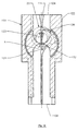
- FIG. 14 is a cross-section view of an anvil 74 of a fitment applicator device.
- a fitment applicator device is disclosed in U.S. Patent Number 5,601,669.
- the vacuum holding device 76 is integrated within the anvil 74.
- the vacuum holding device 76 is composed of an engagement piece 77, a central vacuum passage 82, an ancillary passage 84, and a vacuum tube engagement 86.
- the passages 82 and 84 are integrated within the body 90 of the anvil 74.
- One end of a tube 92, not shown, is placed within engagement 86 while the other end of the tube 92 is connected to a pressure control source 94, not shown.
- the pressure control source 94 may exert a vacuum by evacuating air from the various passageways, or when necessary operate in reverse to increase the pressure through the passageways.
- the anvil 74 When a vacuum is exerted, air is evacuated through the tube 92 through the passage 82 from the engagement piece 77, through an engagement passage 96 and through an aperture 200 for attachment of a closure 20 thereto.
- the anvil 74 may be operated as described in any of the above incorporated patents or application.
- the pressure control source 94 is reversed thereby increasing the pressure in the passageways which results in the closure being "blown off' the engagement piece 77 substantially simultaneously with the attachment of the closure 20 to the container, either by ultrasonic welding or other means such as hot melt adhesion.
- the timing of the reversal of the pressure control source 94 is controlled by a programmable logic control (“PLC”) which also controls the movement of the anvil and attachment device.
- PLC programmable logic control
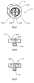
- FIGS. 15-17 illustrate the engagement piece 77 of the vacuum holding device.
- the face 201 of the engagement piece 77 may have an annular groove 204 encircling a lobe 206 on which the aperture 200 is located for exerting the vacuum therefrom.
- the lobe 206 may also have a series of lobe channels 208 thereon for allowing the projection 28 to rests within during capture of a closure 20 on the engagement piece 77.
- the operation of vacuum holding device is described with the operation of the entire system 300 as described below.
- a plurality of closures 20 are fed from a hopper 66 through a chute 68 to the orienting device 30.
- the closures 20 are properly oriented for placement on a carton no matter what orientation the closures 20 possess when entering the orienting device 30.
- Gravity assists in the orienting of the closure 20 as it maneuvers through the channels 40-46 and 70 of the orienting device 30.
- the closure is positioned with the cap able to be opened upward if the closure is a flip cap closure. Alternatively, a non-flip cap closure will have a proper orientation corresponding to the opening mechanism.
- an anvil 74 may engage the closure 20 for positioning about a carton or container.
- the anvil 74 may position the closure 20 within an open-ended carton or attach the closure 20 to the exterior of a sealed carton.
- the anvil 74 may engage the closure 20 with a spud 72, or if the anvil 74 is integrated with the vacuum holding device 76 of the present invention, it may engage the closure 20 with an engagement piece 77 which has an aperture in flow communication with a pressure control source 94 for exerting a vacuum on the closure 20 for retention to the engagement piece 77 during movement of the anvil 74.
- the anvil 74 will move from a closure/fitment attachment station to the carton for attachment of the closure 20 thereon.
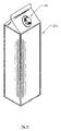
- FIG. 18 A sealed carton 202 with a closure there attached is shown in FIG. 18.
- the present invention may be integrated on a form, fill and seal packaging machine, or positioned before or after the machine for attachment of a closure to a blank or sealed carton respectively.
Landscapes
- Engineering & Computer Science (AREA)
- Mechanical Engineering (AREA)
- Closing Of Containers (AREA)
- Making Paper Articles (AREA)
- Liquid Crystal (AREA)
- Electrostatic Spraying Apparatus (AREA)
- Closures For Containers (AREA)
- Lock And Its Accessories (AREA)
- Container, Conveyance, Adherence, Positioning, Of Wafer (AREA)
- Electrophotography Configuration And Component (AREA)
Abstract
Description
- The present invention relates to an apparatus for orienting a fitment for attachment to a container. Specifically, the present invention relates to an apparatus for. orienting an orientationally sensitive fitment on a carton.
- Containers having spout-like closures for dispensing the contents therefrom have come into widespread use. One such type of closure includes a threaded spout extending upwardly from a container. The closure is used with a cap that threadly engages the spout. Frequently, such closures are injection molded directly onto the container material stock. Such closures may, however, be formed separate from the container and subsequently mounted thereto. For certain applications, such closures have shown significant advantages over known closure systems.
- Another known type of closure includes a one-piece molded body having a hinged cap. Such one piece closures advantageously eliminate the need for a separately formed closure cap. The one-piece configuration eliminates the possibility of losing or inadvertently discarding the separate cap portion.
- One drawback to using such hinged closures is that each closure must be properly oriented on its respective container because each closure cover hinges or pivots about an axis particularly located on the closure. For example, the cover portion of a hinged closure that is mounted to a gable top carton must pivot upwardly, out of the way of the contents being dispensed or poured from the container. If the cover pivots in a manner or direction other than upwardly, it may interfere with dispensing or pouring of the contents therefrom.
- In another application, it may be desired to position a non-hinged closure, such as a threaded closure package, in a particular orientation on a container. Such particularized orientation of the closure may be, for example, to effect the proper positioning of indicia on the closure or closure cap relative to the container. This may be significant if the indicia contains a logo, trademark or like representation.
- Known orientable closures typically have one or more flattened sides to facilitate proper orientation of the closure on the container. Inasmuch as such partially flattened closures are acceptable for hinged type closures, there are a number of drawbacks. First, such flattened sides may increase the cost to manufacture such closures. In addition, handling and positioning of such closures could require additional capital equipment for. sorting, positioning and mounting the closures to containers. Moreover, such flattened closures are difficult to use in conjunction with a threaded-type closure arrangement.
- Accordingly, there continues to be a need for. an orientationally sensitive closure and an orienting apparatus for use with such a closure. Such a closure and apparatus should readily orient the closure for proper positioning for mounting to a container. Such a closure should include a hinged cover portion that opens away from the dispensing direction. Advantageously, such a closure may include directionally sensitive indicia, such as logos and the like, which indicia should be properly oriented on the closure.
- The present invention is directed at apparatus for orienting a closure prior to its attachment to a container. It is for use with a closure having a flange with a spout extending from a side thereof centrally positioned on and coaxial with the flange, and an orienting projection extending from an opposite side of the flange, the flange having a width and the orienting projection having a thickness less than said width. The apparatus comprises a first and second edging defining a projection receiving channel with a receiving end and a dispensing end, and at least one bend therein defining a portion extending generally transverse, in part, relative to a longitudinal axis thereof; and a flange receiving channel defined by a plurality of longitudinal bars extending at least the length of the first and second edging and in proximity thereof for maintaining a closure flange within the flange receiving channel. It will be appreciated that apparatus according to the invention may be an integrated or an add-on component in a closure system or to a fitment applicator for a form, fill and seal packaging machine.
- Apparatus of the invention will normally include a vacuum device at the base thereof. It will also normally include an anvil for supporting the closure prior to attachment to the container.
- In apparatus of the invention an anvil may be included which itself includes a vacuum holding device. In this embodiment, the anvil may comprises an anvil body with a receiving lobe disposed on an end thereof for receiving the closure thereon; and a vacuum holding device disposed within the anvil, the vacuum holding device having a passageway extending from a vacuum source on one end to an aperture disposed centrally on the receiving lobe on the other end; whereby exerting a vacuum holds a closure disposed on the lobe during transport from an orienting apparatus to a container.
- The invention will now be described by way of example and with reference to the accompanying drawings wherein:
- FIG. 1 is a top plan view of a closure suitable for orientation in apparatus of the present invention;
- FIG. 2 is a side view of the closure of FIG. 1;
- FIG. 3 is a front plan view of orienting apparatus according to a first embodiment of the invention, and showing an anvil for receiving the closure therefrom; and a closure at the entrance thereto;
- FIG. 4 is a front plan view of the apparatus of FIG. 3 showing the closure at a first stage of orientation;
- FIG. 5 is a front plan view of the apparatus of FIG. 3 showing the closure at a second stage of orientation;
- FIG. 6 is a front plan view of the apparatus of FIG. 3 showing the closure at a third stage of orientation;
- FIG. 6A is a cross-sectional view taken on line II-II of FIG. 6;
- FIG. 7 is a front plan view of the apparatus of FIG. 3 with a plurality of closures being oriented on the device;
- FIG. 7A is an end view of the apparatus of FIG.7;
- FIG. 8 is a front view of apparatus according to a second embodiment of the present invention;
- FIG. 9 is an end view of the apparatus of FIG. 8;
- FIGS. 10A-E diagrammatically illustrate a directionally sensitive closure as it traverses through the orienting apparatus of FIG. 8;
- FIG. 11 is a front view of apparatus according to a third embodiment of the present invention;
- FIGS. 12A-E diagrammatically illustrate a directionally sensitive closure as it traverses through the orienting apparatus of FIG. 11;
- FIG. 13 diagrammatically illustrates the apparatus of FIG. 11 with a closure having entered the apparatus in a near leading position, and resting in the apparatus cradle;
- FIG. 14 is a cross-sectional view of an anvil and vacuum holding device as used with apparatus of the present invention;
- FIG. 15 is a perspective view of the face of the vacuum holding device of FIG. 14;
- FIG. 16 is a top plan view of the front of the vacuum holding device of FIG. 14;
- FIG. 17 is a cross-sectional view of the front of the vacuum holding device of FIG. 14; and
- FIG. 18 is a perspective view of a carton with a closure thereon.
-
- FIGS. 1 and 2 illustrate a
closure 20 which is applied to a carton in order to access the contents of the carton. The closure has acap 20, aspout 24, ahinge 25, aflange 26, a flat portion of aflange 27 and anorienting projection 28. Theflat portion 27 of the flange assists in having theclosure 20 the rests in the proper position for engagement with a spud of an anvil as described below. The orientingprojection 28 guides theclosure 20 through an orientingdevice 30 as shown in FIGS. 3-7. - FIGS 3-7 illustrate the
closure 20 at different points in time as theclosure 20 is oriented on the orientingdevice 30. In a basic embodiment, the orientingdevice 30 is composed of a series ofparallel rods 32A-B and 34A-B, a first multi-angled edging 36, a second multi-angled edging 38, and ageneral channel 40. Theparallel rods parallel rods edgings channel 40 defining yet a fourth plane. Thegeneral channel 40 may be further partitioned into anupper channel 42, amiddle channel 44 and alower channel 46. Theedgings first plate 48 and asecond plate 50. Alternatively, one or theother plates perpendicular edge 52 connected to a first declinededge 54 connected to a firstinclined edge 56 connected to a firstparallel edge 58. The second multi-angled edging 38 may be further partitioned into a secondperpendicular edge 60 connected to a second declinededge 62 connected to a secondparallel edge 64. - FIGS. 3-7 illustrate a plan view of the orienting
device 30 with aclosure 20 or closures being oriented thereon. The top of theclosure 20 is facing outward, however the main function of theclosure 20 is operable from its bottom, that being the orientingprojection 28. Thus, the closure will be shown as outlined to emphasize the action of the orientingprojection 28. Theclosures 20 are supplied from a hopper 66, not shown, which is connected to the orientingdevice 30 via a chute 68, not shown. No matter what the orientation, or angle, of theclosures 20 as eachclosure 20 emerges from the chute 68, the orientingdevice 30 will properly orient the closure once theclosure 20 emerges from the orientingdevice 30. - As a closure enters the orienting
device 30, the perimeter of theflange 26 engages with theparallel rods flange channel 70 which is defined by theparallel rods 32A-B and 34A-B withrods channel 70 androds channel 70 which is best seen in FIG. 6A. Thus, the very perimeter edging of theflange 26 is trapped betweenrods 32A-B and 34A-B which directs theclosure 20 downward thereby preventing outward, transversal, movement of theclosure 20. - Once the
closure 20 has entered the orientingdevice 30, the orientingprojection 28 engages with the edging 36 or 38, as shown in FIG. 4. The orientingprojection 28 maneuvers within thegeneral channel 40 and depending on the orientation of theclosure 20 as it leaves the chute 68, theprojection 28 may first engage with the first multi-angled edging 36 or the second multi-angled edging 38. Theprojection 28 may "bounce" between the edging 36 and 38 as theclosure 20 drops through the orientingdevice 30. - Eventually the
projection 28 will enter themiddle channel 44 as shown in FIG. 5. At this point in time, theclosure 20 is being readied for proper positioning for engagement with theface 72 ofanvil 74, not shown. Theface 72 may be an engagement mechanism of avacuum holding device 76 or a spud of atraditional anvil 74. Such is described below in reference to thevacuum holding device 76. A proper position/orientation has theflat portion 27 of theflange 26 exiting the orientingdevice 30 first and perpendicular to theparallel rods 32A-B and 34A-B. However, withclosures 20 that do not have aflat portion 27, the proper orientation has thecap 22 able to open upward toward the orientingdevice 30 with thehinge 25 at the top of theclosure 20. - FIG. 6A illustrates a cross-sectional view of a
closure 20 within the orientingdevice 30. Theprojection 28 is within thelower channel 46 which is the most narrow channel of the three sub-channels 42,44 and 46 of thegeneral channel 40. Theflange 26 lies within theflange channel 70. Alternatively,parallel rods plates plates flange channel 70. In such an embodiment as shown in FIG. 7, the orientingdevice 30 would be composed of essentially aflat body 80 which hasedgings 36A and 38B protruding therefrom, and alsoparallel rods edgings flat body 80 hasedgings Parallel rods flat body 80 define theflange channel 70. Theprojection 28 still resides in lower channel 46A. Also, FIG, 7 demonstrates how a plurality ofclosures 70 being continually fed from the chute 68 would maneuver through the orientingdevice 30 and become properly oriented no matter what orientation theclosures 20 possessed when each closure entered the orientingdevice 30. - Another embodiment of an
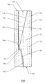
apparatus 160 for orienting theclosures 20 is illustrated in FIGS. 8-10. Theapparatus 160 is a gravity feed type device that uses gravity acting on theclosures 20 as the motive force for moving theclosures 20 through theapparatus 160 and orienting theclosures 20 as they traverse through and exit therefrom. The orientingapparatus 160 includes abody portion 162 having aninlet region 164 and anoutlet region 166. Thebody 162 defines a longitudinal axis, as indicated at 168, between theinlet 164 andoutlet 166 regions. First, second and third receivingchannels body 162 extending between the inlet andoutlet regions channels spout 118,flange 116 and orientingprojection 132, respectively. - The first and
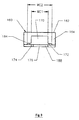
second channels body 162 defining relatively straight-through paths between the inlet and outlet regions 164,166. As best seen in FIG. 9, each the first andsecond channels closure 20 to freely slide or traverse through theapparatus 160. - As best seen in FIG. 8, the
third channel 174, i.e., the orienting projection channel, has a path that includes an inward taper from theinlet region 164, as indicated at 176, and a plurality of bends, preferable, two bends, as indicated at 178 and 180, respectively, between the inlet andoutlet regions channel 174 includes two bends, thebends channel 174 can include one or more additional bends, such as the exemplarythird bend 182, to discharge theclosures 20 in a path parallel to the longitudinal axis 68. - A diagrammatic illustration of a
closure 20 traversing through the orientingapparatus 160 is shown in FIGS. 10 a-e. It will be readily apparent from the figures and the present description that theclosure 20 will exit or will be discharged from the orientingapparatus 160 with theleading edge 138 first exiting ( in a leading position) theapparatus 160 and the trailingedge 140 last exiting ( in a trailing position) theapparatus 160. It is to be noted that theapparatus 160 is oriented with thelongitudinal axis 168 positioned in a vertical or near vertical orientation. In a current embodiment, thelongitudinal axis 168 is positioned between a vertical orientation and about 30° from the vertical. - FIG. 10a shows a
closure 20 as it traverses through theapparatus 160. Thespout 118 is positioned within thespout channel 170, theflange 116 is positioned within theflange channel 172 and the orientingprojection 132 is positioned within theprojection channel 174. Theclosure 20 is illustrated with the trailingedge 140 or a trailing portion of theclosure 20 in a leading position. As theclosure 20 moves downward in theapparatus 160, theprojection 132 can contact one of thesides 183 of thechannel 174. The resistance generated by contact between theprojection 132 and achannel side 183 begins to rotate theclosure 20 so that theprojection 32 shifts to a trailing position. That is, theleading edge 138 will begin to rotate into a leading position as theclosure 20 moves toward theoutlet region 166. - Referring to FIG. 10b, as the
closure 20 traverses further into theapparatus 160, theprojection 132 is directed against awall 184 that is defined by thefirst bend 178 in theprojection channel 174. Gravity acting on theclosure 20, and more particularly, gravity acting on the center of gravity of the closure 20 ( which for purposes of the present discussion is assumed to be at about the center of the closure 20) further rotates theclosure 20 as it pivots about theprojection 132 which is contacting thewall 184. - As shown in FIG. 10c, the
closure 20 continues to rotate which moves theprojection 132 off of thewall 184, around thesecond bend 180, and into a vertical or nearvertical portion 186 of theprojection channel 174. The continued rotation of theclosure 20 is due to gravitational forces acting on theclosure 20 as theprojection 132 contacts or drags against thesides 183 of thechannel 174. - At this point, as shown in FIGS. 10d-e, the
closure 20 has been rotated so that it is oriented with theleading edge 138 in the leading position and the trailingedge 140 in the trailing position. It is important to note that thechannel closure 20 passes thesecond bend 180 it cannot continue rotating so as to pass beyond the desired leading edge orientation to permit the trailing edge to lead. Theclosure 20 then exists or is discharged from theapparatus 160 properly oriented, with theleading edge 138 first exiting theapparatus 160, i.e., with theleading edge 138 in a leading position. - It will be apparent from the figures that when a
closure 20 enters theapparatus 160 with theleading edge 138 in a leading position, the above discussion applies, however, the extent of rotation of theclosure 20 will be less than it is with theclosure 20 entering theapparatus 160 by the trailingedge 140. - An
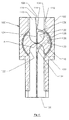
alternate embodiment 100 of the orienting apparatus is illustrated in FIGS. 11-12. The orientingapparatus 100 includes amain body 102 having aninlet region 104 and anoutlet region 106. The body defines a longitudinal axis, as indicated at 108, that extends between the inlet and theoutlet regions channels body 102 extending between the inlet andoutlet regions channels spout 118,flange 116 and orientingprojection 132, respectively. Thethird channel 114, i.e., the projection channel, can be configured with a tapered inlet, as indicated at 116, to facilitate introducing theclosures 20 to theapparatus 100. - The orienting
apparatus 100 includes arotating cylinder 118 positioned on thebody 102, in the path of travel of theclosures 20, intermediate the inlet andoutlet regions cylinder 118 rotates about an axis A, and includes at least one, and preferably two, opposingly oriented,semicircular cradle regions cradle regions closures 20, at about thespout 118, and transport theclosure 180° from theinlet region 104 to theoutlet region 106. Thecylinder 118 is positioned in the path of, and intersecting, the first and second channels, 110, 112 i.e., the spout and flange channels, and is positioned, as illustrated in FIG. 11, above thethird channel 114, i.e., projection channel. - The first and
second channels cylinder 118 as will be described herein. Thethird channel 114 has a pair ofbranches first branch 124 has a straight-through path. Thesecond branch 126 follows a diverging-converging path, and diverges outwardly, arcuately from the first path at about a periphery of the cylinder, as indicated at 128. The divergingportion 128 of the path extends a distance about equal to a 90° rotation of thecylinder 118. The divergingpath 128 transitions as indicated at 130, reversing direction, to an inwardly, arcuately extendingpath 133 that converges with the straight-through. The convergingportion 133 of the path conjoins with the straight-throughpath 124, as indicated at 134, at a distance about equal to a 90° rotation of thecylinder 118. - Essentially, the
third channel 114 has a two paths, a straight-throughpath 124 and anarcuate path 126. Thearcuate path 126 has an outwardly, arcuately divergingportion 128 that transitions, as indicated at 130, to an inwardly, arcuately convergingportion 132, that conjoins, as indicated at 134, with the straight-throughpath 124. - In operation, similar to the
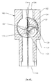
embodiment 160, with reference now to FIGS. 12a-d, the orientingapparatus 100 is configured to slidingly receive aclosure 20 with theprojection 132 extending into thethird channel 114, and to reorient theclosure 20 such that theclosure 20 exits or is discharged from theapparatus 100 with the leadingedge 38 exiting theapparatus 100 in a leading position. - The operation of the
apparatus 100 will be first described with aclosure 20 entering theapparatus 100 with the projection 132 (i.e., the trailing edge 140) in a trailing position. As shown in FIG. 12a, theclosure 20 is presented to theinlet region 104 of theapparatus 1 00. Thetapered inlet 116 of thechannel 114 directs theclosure 20 such that theleading edge 138 of theclosure 20 first enters thecylinder 118 and the spout 18 rests in thecradle 120. As best seen in FIG. 12a, theprojection 132 is at the point of divergence of thethird channel 114. As thecylinder 118 rotates clock-wise, theclosure 20 remains stationary relative to thecradle 120, but rotates clock-wise with therotating cradle 120. As theclosure 20 rotates, theprojection 132 moves along the divergingpath 128, as illustrated in FIG. 12b. - As this point, as shown in FIG. 12b, the
projection 132 is resting against the channel wall at thetransition 130. As thecylinder 118 further rotates clock-wise, theprojection 132 is urged along the convergingpath 133, and theclosure 20 rotates counter clock-wise as shown in FIG. 12c, relative to, and as thecradle 120 rotates. As thecradle 120 comes into alignment with theoutlet region 106, theprojection 132 is oriented rearward with theleading edge 138 of theclosure 20 directed toward theoutlet region 106. As theclosure 20 exits from theapparatus 100, theleading edge 138 is first discharged therefrom. - FIG. 13 illustrates the
apparatus 100 of FIG. 11, with aclosure 20 entering theapparatus 100 with the trailingedge 140 in a leading position. Theclosure 20 is presented to theapparatus 100 and traverses downward to position thespout 118 in thecradle 120. In this position, theprojection 132 is collinear with the axis A. As thecradle 120 rotates, theprojection 132 is held in place in the straight-throughportion 124 of thethird channel 114 and serves as a pivot for theclosure 20. As thecradle 120 rotates, theclosure 20 rotates about 180° with thecradle 120, about theprojection 132. Theclosure 20 is then discharged from thecradle 120 and theapparatus 100 with theleading edge 138 first discharged therefrom, i.e., with theleading edge 138 in a leading position. - The
vacuum holding device 76 is shown in FIG. 14 which is a cross-section view of ananvil 74 of a fitment applicator device. Such a fitment applicator device is disclosed in U.S. Patent Number 5,601,669. - The
vacuum holding device 76 is integrated within theanvil 74. Thevacuum holding device 76 is composed of anengagement piece 77, acentral vacuum passage 82, anancillary passage 84, and avacuum tube engagement 86. Thepassages body 90 of theanvil 74. One end of a tube 92, not shown, is placed withinengagement 86 while the other end of the tube 92 is connected to a pressure control source 94, not shown. The pressure control source 94 may exert a vacuum by evacuating air from the various passageways, or when necessary operate in reverse to increase the pressure through the passageways. When a vacuum is exerted, air is evacuated through the tube 92 through thepassage 82 from theengagement piece 77, through anengagement passage 96 and through anaperture 200 for attachment of aclosure 20 thereto. Once the closure/fitment 20 is attached to theengagement piece 77, theanvil 74 may be operated as described in any of the above incorporated patents or application. Once the anvil is maneuvered to a container, the pressure control source 94 is reversed thereby increasing the pressure in the passageways which results in the closure being "blown off' theengagement piece 77 substantially simultaneously with the attachment of theclosure 20 to the container, either by ultrasonic welding or other means such as hot melt adhesion. The timing of the reversal of the pressure control source 94 is controlled by a programmable logic control ("PLC") which also controls the movement of the anvil and attachment device. - FIGS. 15-17 illustrate the
engagement piece 77 of the vacuum holding device. Theface 201 of theengagement piece 77 may have anannular groove 204 encircling alobe 206 on which theaperture 200 is located for exerting the vacuum therefrom. Thelobe 206 may also have a series oflobe channels 208 thereon for allowing theprojection 28 to rests within during capture of aclosure 20 on theengagement piece 77. The operation of vacuum holding device is described with the operation of theentire system 300 as described below. - A plurality of
closures 20 are fed from a hopper 66 through a chute 68 to the orientingdevice 30. At the orientingdevice 30, theclosures 20 are properly oriented for placement on a carton no matter what orientation theclosures 20 possess when entering the orientingdevice 30. Gravity assists in the orienting of theclosure 20 as it maneuvers through the channels 40-46 and 70 of the orientingdevice 30. At the bottom of the orientingdevice 30, the closure is positioned with the cap able to be opened upward if the closure is a flip cap closure. Alternatively, a non-flip cap closure will have a proper orientation corresponding to the opening mechanism. - Once in a proper position, an
anvil 74 may engage theclosure 20 for positioning about a carton or container. Theanvil 74 may position theclosure 20 within an open-ended carton or attach theclosure 20 to the exterior of a sealed carton. Theanvil 74 may engage theclosure 20 with aspud 72, or if theanvil 74 is integrated with thevacuum holding device 76 of the present invention, it may engage theclosure 20 with anengagement piece 77 which has an aperture in flow communication with a pressure control source 94 for exerting a vacuum on theclosure 20 for retention to theengagement piece 77 during movement of theanvil 74. Theanvil 74 will move from a closure/fitment attachment station to the carton for attachment of theclosure 20 thereon. - If the
vacuum holding device 20 of the present invention is utilized, a vacuum is exerted during the engagement of aclosure 20 to theanvil 74, and maintained until theclosure 20 is permanently affixed to the carton. A sealedcarton 202 with a closure there attached is shown in FIG. 18. The present invention may be integrated on a form, fill and seal packaging machine, or positioned before or after the machine for attachment of a closure to a blank or sealed carton respectively.
Claims (11)
- Apparatus for orienting a closure for attachment to a container, the closure having a flange (26) with a spout (24) extending from a side thereof centrally positioned on and coaxial with the flange, and an orienting projection (28) extending from an opposite side of the flange, the flange having a width and the orienting projection having a thickness less than said width, which apparatus comprises a first and second edging (36,38) defining a projection receiving channel (40) with a receiving end and a dispensing end, and at least one bend therein defining a portion extending generally transverse, in part, relative to a longitudinal axis thereof; and a flange receiving channel defined by a plurality of longitudinal bars (32,34) extending at least the length of the first and second edging (36,38) and in proximity thereof for maintaining a closure flange within the flange receiving channel.
- Apparatus according to Claim 1 including a vacuum holding device (76) disposed at the bottom of the orienting apparatus.
- Apparatus according to Claim 2 including an anvil for supporting the closure prior to attachment to a container.
- Apparatus according to Claim 3 wherein the anvil comprises an anvil body with a receiving lobe disposed on an end thereof for receiving the closure thereon; and a vacuum holding device (76) disposed within the anvil, the vacuum holding device having a passageway extending from a vacuum source on one end to an aperture disposed centrally on the receiving lobe on the other end; whereby exerting a vacuum holds a closure disposed on the lobe during transport from an orienting apparatus to a container.
- Apparatus according to any preceding Claim wherein the orienting apparatus includes a flat body, the first and second edging (36,38) protruding from the flat body.
- Apparatus according to any preceding Claim wherein the projection receiving channel comprises an upper channel (42) having a first width, a middle channel (44) having a second width smaller than the first width, and a lower channel (46) having a third width smaller than the second width.
- Apparatus according to any preceding Claim wherein the first edging (36) comprises a first perpendicular edge (52); a first declined edge (54), a first inclined edge (56) and a first parallel edge (58).
- Apparatus according to Claim 7 wherein the second edging comprises a second perpendicular edge (60), a second declined edge (62) and a second parallel edge (64).
- Apparatus according to any preceding Claim wherein each of the first and second edging is defined by a single rod (36,38).
- Apparatus according to any preceding Claim comprising a pair of longitudinal bars (32,34) positioned on either side of the projection receiving channel for retaining a closure flange (26), and a said projection (28) in the projection receiving channel.
- A closure system for attaching an orientationally sensitive closure on a container, comprising apparatus according to any preceding Claim.
Applications Claiming Priority (5)
| Application Number | Priority Date | Filing Date | Title |
|---|---|---|---|
| US08/812,319 US5852913A (en) | 1997-03-05 | 1997-03-05 | Orientationally sensitive closure and orienting apparatus therefor |
| US812319 | 1997-03-05 | ||
| US08/996,606 US5992129A (en) | 1997-03-05 | 1997-12-23 | Orienting apparatus for an orientationally sensitive closure |
| US996606 | 1997-12-23 | ||
| PCT/US1998/003996 WO1998039210A1 (en) | 1997-03-05 | 1998-02-27 | Orienting apparatus for an orientationally sensitive closure |
Publications (2)
| Publication Number | Publication Date |
|---|---|
| EP1030808A1 EP1030808A1 (en) | 2000-08-30 |
| EP1030808B1 true EP1030808B1 (en) | 2004-04-21 |
Family
ID=27123594
Family Applications (1)
| Application Number | Title | Priority Date | Filing Date |
|---|---|---|---|
| EP98908826A Expired - Lifetime EP1030808B1 (en) | 1997-03-05 | 1998-02-27 | Orienting apparatus for an orientationally sensitive closure |
Country Status (10)
| Country | Link |
|---|---|
| US (1) | US5992129A (en) |
| EP (1) | EP1030808B1 (en) |
| JP (1) | JP4143132B2 (en) |
| AT (1) | ATE264788T1 (en) |
| AU (1) | AU731716B2 (en) |
| DE (1) | DE69823385T2 (en) |
| NO (1) | NO314490B1 (en) |
| RU (1) | RU2180645C2 (en) |
| SE (1) | SE517161C2 (en) |
| WO (1) | WO1998039210A1 (en) |
Families Citing this family (9)
| Publication number | Priority date | Publication date | Assignee | Title |
|---|---|---|---|---|
| JP4002616B2 (en) * | 1996-11-01 | 2007-11-07 | テトラ ラバル ホールデイングス エ フイナンス ソシエテ アノニム | Integrated molded flip cap lid device |
| US6125610A (en) * | 1999-08-19 | 2000-10-03 | Tetra Laval Holdings & Finance, Sa | Anvil for closure mounting |
| SE523971C2 (en) * | 2001-12-10 | 2004-06-08 | Tetra Laval Holdings & Finance | Device for gripping and holding objects |
| JP4038058B2 (en) * | 2002-03-13 | 2008-01-23 | 大日本印刷株式会社 | Outlet circumferential positioning device and spout circumferential positioning supply device |
| CA124243S (en) * | 2007-07-05 | 2008-09-29 | Tetra Laval Holdings & Finance | Material for packaging |
| GB0717803D0 (en) * | 2007-09-13 | 2007-10-24 | Reckitt Benckiser Inc | Improved process for manufacturing dispensing devices |
| CN102328755B (en) * | 2011-10-09 | 2013-01-02 | 广东粤东机械实业有限公司 | Continuous sealing and cutting machine |
| JP6824592B1 (en) * | 2019-12-12 | 2021-02-03 | テトラ ラバル ホールディングス アンド ファイナンス エス エイ | Opening device mounting device and filling machine |
| AT526279B1 (en) * | 2022-06-27 | 2024-09-15 | Gassner Verwaltungs Gmbh | Method for conveying and orienting pouring elements with closure and conveying device |
Family Cites Families (8)
| Publication number | Priority date | Publication date | Assignee | Title |
|---|---|---|---|---|
| US2972184A (en) * | 1957-11-29 | 1961-02-21 | Andrew & Waitkens Machine Co I | Machine for mounting spouts in the tops of containers |
| US3408788A (en) * | 1966-07-18 | 1968-11-05 | American Flange & Mfg | Method and apparatus for securing closure caps to containers |
| GB2112344B (en) * | 1981-02-27 | 1985-01-30 | Shibuya Kogyo Co Ltd | Method and device for mounting a plug on a paper container |
| US4696143A (en) * | 1986-05-06 | 1987-09-29 | William P. Young Co. | Container capping apparatus |
| JPH07280Y2 (en) * | 1989-10-31 | 1995-01-11 | 日本製紙株式会社 | Spout insertion device for container |
| US5159797A (en) * | 1991-02-15 | 1992-11-03 | Herzog Kenneth J | Ball cap orienter |
| US5150559A (en) * | 1991-10-07 | 1992-09-29 | Plant Services Corp. | Fluid container capper apparatus |
| US5601669A (en) * | 1994-10-04 | 1997-02-11 | Portola Packaging, Inc. | Apparatus and method for attaching fitments to cartons |
-
1997
- 1997-12-23 US US08/996,606 patent/US5992129A/en not_active Expired - Lifetime
-
1998
- 1998-02-27 JP JP53864198A patent/JP4143132B2/en not_active Expired - Lifetime
- 1998-02-27 DE DE69823385T patent/DE69823385T2/en not_active Expired - Lifetime
- 1998-02-27 AT AT98908826T patent/ATE264788T1/en not_active IP Right Cessation
- 1998-02-27 AU AU66765/98A patent/AU731716B2/en not_active Expired
- 1998-02-27 EP EP98908826A patent/EP1030808B1/en not_active Expired - Lifetime
- 1998-02-27 RU RU99120784/13A patent/RU2180645C2/en active
- 1998-02-27 WO PCT/US1998/003996 patent/WO1998039210A1/en not_active Ceased
-
1999
- 1999-09-03 NO NO19994296A patent/NO314490B1/en not_active IP Right Cessation
- 1999-09-03 SE SE9903135A patent/SE517161C2/en unknown
Also Published As
| Publication number | Publication date |
|---|---|
| SE517161C2 (en) | 2002-04-23 |
| NO994296D0 (en) | 1999-09-03 |
| SE9903135D0 (en) | 1999-06-03 |
| DE69823385D1 (en) | 2004-05-27 |
| JP4143132B2 (en) | 2008-09-03 |
| WO1998039210A1 (en) | 1998-09-11 |
| SE9903135L (en) | 1999-10-19 |
| NO994296L (en) | 1999-11-04 |
| US5992129A (en) | 1999-11-30 |
| DE69823385T2 (en) | 2004-08-26 |
| AU731716B2 (en) | 2001-04-05 |
| JP2001513718A (en) | 2001-09-04 |
| ATE264788T1 (en) | 2004-05-15 |
| RU2180645C2 (en) | 2002-03-20 |
| EP1030808A1 (en) | 2000-08-30 |
| NO314490B1 (en) | 2003-03-31 |
| AU6676598A (en) | 1998-09-22 |
Similar Documents
| Publication | Publication Date | Title |
|---|---|---|
| US9309041B2 (en) | Container fitment having ellipsoidal opening | |
| EP0965438B1 (en) | Apparatus for bonding pour spout to containers | |
| US5320146A (en) | Volumetric feeder with belt gate | |
| EP0749904B1 (en) | Container fitment applicator and corresponding method | |
| GB1575692A (en) | Vertical form fill and seal packaging machine with back-up bar for longitudinal sealing | |
| AU731716B2 (en) | Orienting apparatus for an orientationally sensitive closure | |
| US5435803A (en) | Container fitment applicator | |
| CZ284184B6 (en) | Apparatus for sterilizing cardboards and their bending along grooved spots | |
| JPH0349804B2 (en) | ||
| US5852913A (en) | Orientationally sensitive closure and orienting apparatus therefor | |
| FI98354C (en) | Device for filling the package | |
| US6719015B2 (en) | Apparatus and process for manufacturing a filled flexible pouch | |
| US6430896B1 (en) | Capping machine | |
| US4171603A (en) | Guide mechanism for loading wide mouth bottles in cases | |
| US5335474A (en) | Apparatus for supplying containers to a sealing device | |
| EP0356500B1 (en) | Packaging machine jamming detector | |
| US4998911A (en) | Lid alignment and fixing apparatus | |
| US5885044A (en) | Parts supplying apparatus and parts array | |
| JPH03687A (en) | Method and apparatus for sealing container mouth together with distributor | |
| JP3429804B2 (en) | Device for inserting tube container into carrier | |
| EP0885143B1 (en) | Parts supplying apparatus | |
| US20070051070A1 (en) | Alignment apparatus for packaging elements | |
| AU730841B2 (en) | Parts supplying apparatus and parts array | |
| CH639615A5 (en) | METHOD AND DEVICE FOR PACKAGING SUBSTANTIALLY CONSTANT GEOMETRIC PRODUCTS. | |
| JPH1159625A (en) | Filling device for packaging container |
Legal Events
| Date | Code | Title | Description |
|---|---|---|---|
| PUAI | Public reference made under article 153(3) epc to a published international application that has entered the european phase |
Free format text: ORIGINAL CODE: 0009012 |
|
| 17P | Request for examination filed |
Effective date: 19991004 |
|
| AK | Designated contracting states |
Kind code of ref document: A1 Designated state(s): AT BE CH DE DK ES FI FR GB GR IE IT LI LU MC NL PT SE |
|
| 17Q | First examination report despatched |
Effective date: 20021106 |
|
| GRAP | Despatch of communication of intention to grant a patent |
Free format text: ORIGINAL CODE: EPIDOSNIGR1 |
|
| GRAS | Grant fee paid |
Free format text: ORIGINAL CODE: EPIDOSNIGR3 |
|
| GRAA | (expected) grant |
Free format text: ORIGINAL CODE: 0009210 |
|
| RAP1 | Party data changed (applicant data changed or rights of an application transferred) |
Owner name: TETRA LAVAL HOLDINGS & FINANCE S.A. |
|
| AK | Designated contracting states |
Kind code of ref document: B1 Designated state(s): AT BE CH DE DK ES FI FR GB GR IE IT LI LU MC NL PT SE |
|
| PG25 | Lapsed in a contracting state [announced via postgrant information from national office to epo] |
Ref country code: LI Free format text: LAPSE BECAUSE OF FAILURE TO SUBMIT A TRANSLATION OF THE DESCRIPTION OR TO PAY THE FEE WITHIN THE PRESCRIBED TIME-LIMIT Effective date: 20040421 Ref country code: FI Free format text: LAPSE BECAUSE OF FAILURE TO SUBMIT A TRANSLATION OF THE DESCRIPTION OR TO PAY THE FEE WITHIN THE PRESCRIBED TIME-LIMIT Effective date: 20040421 Ref country code: CH Free format text: LAPSE BECAUSE OF FAILURE TO SUBMIT A TRANSLATION OF THE DESCRIPTION OR TO PAY THE FEE WITHIN THE PRESCRIBED TIME-LIMIT Effective date: 20040421 Ref country code: BE Free format text: LAPSE BECAUSE OF FAILURE TO SUBMIT A TRANSLATION OF THE DESCRIPTION OR TO PAY THE FEE WITHIN THE PRESCRIBED TIME-LIMIT Effective date: 20040421 Ref country code: AT Free format text: LAPSE BECAUSE OF FAILURE TO SUBMIT A TRANSLATION OF THE DESCRIPTION OR TO PAY THE FEE WITHIN THE PRESCRIBED TIME-LIMIT Effective date: 20040421 |
|
| REG | Reference to a national code |
Ref country code: GB Ref legal event code: FG4D |
|
| REG | Reference to a national code |
Ref country code: CH Ref legal event code: EP |
|
| REG | Reference to a national code |
Ref country code: IE Ref legal event code: FG4D |
|
| REF | Corresponds to: |
Ref document number: 69823385 Country of ref document: DE Date of ref document: 20040527 Kind code of ref document: P |
|
| PG25 | Lapsed in a contracting state [announced via postgrant information from national office to epo] |
Ref country code: SE Free format text: LAPSE BECAUSE OF FAILURE TO SUBMIT A TRANSLATION OF THE DESCRIPTION OR TO PAY THE FEE WITHIN THE PRESCRIBED TIME-LIMIT Effective date: 20040721 Ref country code: GR Free format text: LAPSE BECAUSE OF FAILURE TO SUBMIT A TRANSLATION OF THE DESCRIPTION OR TO PAY THE FEE WITHIN THE PRESCRIBED TIME-LIMIT Effective date: 20040721 Ref country code: DK Free format text: LAPSE BECAUSE OF FAILURE TO SUBMIT A TRANSLATION OF THE DESCRIPTION OR TO PAY THE FEE WITHIN THE PRESCRIBED TIME-LIMIT Effective date: 20040721 |
|
| PG25 | Lapsed in a contracting state [announced via postgrant information from national office to epo] |
Ref country code: ES Free format text: LAPSE BECAUSE OF FAILURE TO SUBMIT A TRANSLATION OF THE DESCRIPTION OR TO PAY THE FEE WITHIN THE PRESCRIBED TIME-LIMIT Effective date: 20040801 |
|
| REG | Reference to a national code |
Ref country code: CH Ref legal event code: PL |
|
| ET | Fr: translation filed | ||
| PLBE | No opposition filed within time limit |
Free format text: ORIGINAL CODE: 0009261 |
|
| STAA | Information on the status of an ep patent application or granted ep patent |
Free format text: STATUS: NO OPPOSITION FILED WITHIN TIME LIMIT |
|
| PG25 | Lapsed in a contracting state [announced via postgrant information from national office to epo] |
Ref country code: LU Free format text: LAPSE BECAUSE OF NON-PAYMENT OF DUE FEES Effective date: 20050227 |
|
| PG25 | Lapsed in a contracting state [announced via postgrant information from national office to epo] |
Ref country code: MC Free format text: LAPSE BECAUSE OF NON-PAYMENT OF DUE FEES Effective date: 20050228 Ref country code: IE Free format text: LAPSE BECAUSE OF NON-PAYMENT OF DUE FEES Effective date: 20050228 |
|
| 26N | No opposition filed |
Effective date: 20050124 |
|
| REG | Reference to a national code |
Ref country code: IE Ref legal event code: MM4A |
|
| PG25 | Lapsed in a contracting state [announced via postgrant information from national office to epo] |
Ref country code: PT Free format text: LAPSE BECAUSE OF NON-PAYMENT OF DUE FEES Effective date: 20040921 |
|
| REG | Reference to a national code |
Ref country code: FR Ref legal event code: PLFP Year of fee payment: 19 |
|
| REG | Reference to a national code |
Ref country code: FR Ref legal event code: PLFP Year of fee payment: 20 |
|
| PGFP | Annual fee paid to national office [announced via postgrant information from national office to epo] |
Ref country code: FR Payment date: 20170112 Year of fee payment: 20 Ref country code: DE Payment date: 20170221 Year of fee payment: 20 |
|
| PGFP | Annual fee paid to national office [announced via postgrant information from national office to epo] |
Ref country code: GB Payment date: 20170222 Year of fee payment: 20 Ref country code: NL Payment date: 20170210 Year of fee payment: 20 |
|
| PGFP | Annual fee paid to national office [announced via postgrant information from national office to epo] |
Ref country code: IT Payment date: 20170221 Year of fee payment: 20 |
|
| REG | Reference to a national code |
Ref country code: DE Ref legal event code: R071 Ref document number: 69823385 Country of ref document: DE |
|
| REG | Reference to a national code |
Ref country code: NL Ref legal event code: MK Effective date: 20180226 |
|
| REG | Reference to a national code |
Ref country code: GB Ref legal event code: PE20 Expiry date: 20180226 |
|
| PG25 | Lapsed in a contracting state [announced via postgrant information from national office to epo] |
Ref country code: GB Free format text: LAPSE BECAUSE OF EXPIRATION OF PROTECTION Effective date: 20180226 |