EP1030542A2 - Lead surface coating for an X-ray tube casing - Google Patents
Lead surface coating for an X-ray tube casing Download PDFInfo
- Publication number
- EP1030542A2 EP1030542A2 EP00301215A EP00301215A EP1030542A2 EP 1030542 A2 EP1030542 A2 EP 1030542A2 EP 00301215 A EP00301215 A EP 00301215A EP 00301215 A EP00301215 A EP 00301215A EP 1030542 A2 EP1030542 A2 EP 1030542A2
- Authority
- EP
- European Patent Office
- Prior art keywords
- lead
- ray tube
- casing
- lining
- electroplating material
- Prior art date
- Legal status (The legal status is an assumption and is not a legal conclusion. Google has not performed a legal analysis and makes no representation as to the accuracy of the status listed.)
- Withdrawn
Links
Images

Classifications
-
- H—ELECTRICITY
- H05—ELECTRIC TECHNIQUES NOT OTHERWISE PROVIDED FOR
- H05G—X-RAY TECHNIQUE
- H05G1/00—X-ray apparatus involving X-ray tubes; Circuits therefor
- H05G1/02—Constructional details
Definitions
- This invention relates to x-ray tube casings and particularly to an x-ray tube casing coating for preventing lead contamination of oil.
- the casings of x-ray tubes are lined with lead to prevent the leakage of x-rays in directions other than through the window of the tube.
- This lead is exposed to a dielectric cooling oil which removes heat from the tube insert during operation. X-ray exposure causes a gradual breakdown in the oil forming smaller and less saturated compounds.
- the lead readily oxidizes and a combination of this oxide and particles on the lead surface make coating the lead necessary to prevent oil contamination.
- the present invention provides for electroplating of lead sheet linings for x-ray tube casings, as a replacement for the paint coatings currently used in the art.
- the present invention further addresses the formation and installation of such lead sheet linings, which, if used on prior art structures, would cause peeling of a painted surface.
- Electroplating lead radiation shield material with a corrosion resistant and nontoxic lining material having excellent solderability, softness and ductility, provides a clean corrosion resistant surface which is inert to the oil, independent of temperature and x-ray irradiation.
- the electroplated lead sheet lining material preserves the lead surface from flaking and corroding to the oil.
- the use of electroplated lead allows for lead sheet which can be formed by blanking, drawing, rubber forming, rubber punching and hammering, without peeling of the electroplated coating.
- the lead sheet is electroplated on both sides, and then a surface of the electroplating layer is attached, such as by epoxy, to the aluminum casing.
- the present invention provides a lead sheet lining which has been electroplated on both sides, for attachment to x-ray tube casings, thereby providing a more adherent and durable, and longer-lasting x-ray tube casing coating.
- the present invention relates to rotating x-ray tubes, and particularly to x-ray tube casings.
- the lead surface of the x-ray tube casing is coated with a paint layer.
- Fig. 1 a representative illustration of an x-ray tube casing 26 is shown.
- the x-ray tube casing 26 encases an x-ray tube structure 24, including an anode assembly for distributing heat generated at a focal spot and a cathode assembly for producing x-rays upon impact with the anode.
- Electroplated lead surfaces 28 are described and claimed in co-pending, commonly assigned patent application Serial No. 09/139497, totally incorporated herein by reference.
- the present invention proposes electroplating both sides of a lead sheet lining for subsequent attachment to x-ray tube casings, which is particularly well suited in structures wherein the purpose of the lead sheet lining is to prevent the leakage of x-rays in directions other than through a window of an x-ray tube.
- the electroplated lead sheet lining 28 is exposed to dielectric cooling oil which removes heat from the tube insert during operation.
- the lead which lines the casings of x-ray tubes has provided a poor surface for adherence. Consequently, the dielectric oil, x-rays and various chemicals generated during each x-ray exposure all gradually promote flaking of the paint from the surface.
- electroplated lead can be used for forming lead sheet linings of x-ray tube casings, such as is indicated in Fig. 1. It is well known in the art that the lead lining is exposed to a dielectric cooling oil which removes heat from the tube insert during operation. Hence, the lead lining 28 of the present invention prevents lead contamination of the dielectric cooling oil.
- electroplated lead will allow for lead sheet which can be formed by blanking, drawing, rubber forming, rubber punching, hammering, and various other suitable methods understood by those skilled in the art, without peeling of the electroplated coating. It will further be obvious to those skilled in the art that various metals can be used to create the coating for electroplating the lead surface, including, for example, silver, copper, nickel or tin, or various combinations of these or other metals.
- the electroplated metal for casing lining layer 28 comprises tin.
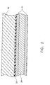
- An electroplated layer 30 is applied to both sides or surfaces of the lead 28, with a preferred thickness of 2 mil, although variation within hundredths, or even tenths of a mil is allowable while still achieving the spirit of the invention.
- Epoxy 32 or other suitable attachment means are used to attach one side of the electroplated layer, comprising the electroplating material and the lead lining, to the aluminum casing 26. Electrodeposits of tin are corrosion resistant and non-toxic, possess excellent solderability and are noted for softness and ductility.
- Electroplating lead radiation shield material with tin provides clean corrosion resistant surfaces which are inert to the oil, independent of temperature and x-ray irradiation.
- the electroplated layer 30 preserves the lead surface 28 from flaking and corroding to the oil.
- the higher thermal conductivity of tin versus the paint of the existing art allows a higher rate of heat transfer from the oil to the casing wall and lowers bulk oil temperature.
- the high ductility of tin allows the electroplated layer to conform to the lead without cracking when the lead is deformed in a radius of 1 cm, and to create a self-healing system, whereby minor scratches repair themselves.
- the problems of poor adherence, cracking with deformation, and flaking that occurs with paint coatings of the prior art are not present for the lead electroplating method of the present invention.
- the ductile lead can be formed to shape after the lead is plated with layers 30. Such forming or shaping would cause increased delamination if performed on painted surfaces of the prior art. Furthermore, having the lead surface electroplated with a metal results in increasing the thermal conductivity from the oil to the casing which is supplied with fins for casing-air heat transfer. This results in a lower oil operating temperature compared to the painted lead lining of the prior art. Electroplating eliminates the environmental and regulatory problems associated with the volatile organic compounds in the paint.
- lead layer 28 After both surfaces, top and bottom, of lead layer 28 are electroplated, such as with tin layers 30, the resultant lead sheet lining can be installed to fabricate the x-ray tube casing structure. Installation may be by any suitable means, such as by applying a layer of epoxy between the tin electroplated layer 30 and the aluminum casing layer 26.
Landscapes
- X-Ray Techniques (AREA)
- Electroplating Methods And Accessories (AREA)
Abstract
Description
Claims (14)
- A rotating x-ray tube comprising:an anode assembly for distributing heat generated at a focal spot;a cathode assembly for producing x-rays upon impact with the anode;a casing for housing the x-ray tube, the casing having a lead lining, the lead lining having a top surface and a bottom surface, and being exposed to a dielectric cooling oil; andan electroplating material for application to the top and bottom surfaces of the lead lining, forming an electroplated layer between the lead lining and the casing.
- A rotating x-ray tube as claimed in claim 1 wherein the electroplating material comprises tin.
- A rotating x-ray tube as claimed in claim 1 or 2 wherein the electroplated layer prevents lead contamination of the dielectric cooling oil.
- A rotating x-ray tube as claimed in claim 1, 2 or 3 wherein the electroplating material imparts insulating properties to the lead lining.
- An x-ray tube casing structure comprising:a lead lining for preventing unwanted leakage of x-rays, the lead lining having a top surface and a bottom surface, with at least one surface being exposed to a dielectric cooling oil; andan electroplating material for coating the top and bottom surfaces of the lead lining to prevent contamination of the dielectric cooling oil.
- An x-ray tube casing structure as claimed in claim 5 further comprising an epoxy layer to attach the lead lining and the electroplating material to the casing.
- An x-ray tube casing structure as claimed in claim 5 or 6 wherein the electroplating material is selected from the group consisting of silver, copper, tin, nickel and combinations of silver, copper, tin and nickel.
- An x-ray tube casing structure as claimed in claim 5 or 6 wherein the electroplating material comprises tin.
- An x-ray tube casing structure as claimed in any one of claims 5 to 8 wherein the electroplating material has a thickness of approximately 2.0 mil.
- A method for providing an adherent and durable coating for an x-ray tube casing comprising the steps of:lining surfaces of the x-ray tube with lead;exposing the lead lined surfaces to a dielectric cooling oil; andcoating the lead lined surfaces with an electroplating material.
- A method as claimed in claim 10 wherein the electroplating material is applied to all surfaces of the lead lining.
- A method as claimed in claim 10 or 11 wherein the electroplating material comprises a corrosion resistant material.
- A method as claimed in claim 10, 11 or 12 wherein the electroplating material comprises a nontoxic material.
- A method as claimed in any one of claims 10 to 12 wherein the electroplating material comprises a ductile material.
Applications Claiming Priority (2)
| Application Number | Priority Date | Filing Date | Title |
|---|---|---|---|
| US253337 | 1999-02-19 | ||
| US09/253,337 US6257762B1 (en) | 1999-02-19 | 1999-02-19 | Lead surface coating for an x-ray tube casing |
Publications (2)
| Publication Number | Publication Date |
|---|---|
| EP1030542A2 true EP1030542A2 (en) | 2000-08-23 |
| EP1030542A3 EP1030542A3 (en) | 2001-10-17 |
Family
ID=22959866
Family Applications (1)
| Application Number | Title | Priority Date | Filing Date |
|---|---|---|---|
| EP00301215A Withdrawn EP1030542A3 (en) | 1999-02-19 | 2000-02-16 | Lead surface coating for an X-ray tube casing |
Country Status (3)
| Country | Link |
|---|---|
| US (1) | US6257762B1 (en) |
| EP (1) | EP1030542A3 (en) |
| JP (1) | JP2000243333A (en) |
Cited By (1)
| Publication number | Priority date | Publication date | Assignee | Title |
|---|---|---|---|---|
| EP1111968A3 (en) * | 1999-12-23 | 2001-10-17 | Vulcan Lead Products Co. | Housing for an x-ray emitting assembly and method of making the same |
Families Citing this family (15)
| Publication number | Priority date | Publication date | Assignee | Title |
|---|---|---|---|---|
| JP3961262B2 (en) * | 2001-10-31 | 2007-08-22 | ジーイー・メディカル・システムズ・グローバル・テクノロジー・カンパニー・エルエルシー | X-ray generator |
| JP3898029B2 (en) * | 2001-10-31 | 2007-03-28 | ジーイー・メディカル・システムズ・グローバル・テクノロジー・カンパニー・エルエルシー | X-ray generator |
| JP3898028B2 (en) | 2001-10-31 | 2007-03-28 | ジーイー・メディカル・システムズ・グローバル・テクノロジー・カンパニー・エルエルシー | X-ray generator |
| JP4828942B2 (en) * | 2003-10-17 | 2011-11-30 | 株式会社東芝 | X-ray equipment |
| US20060008057A1 (en) * | 2004-07-12 | 2006-01-12 | General Electric Company | Structure and method for shielding radiation in an x-ray generator |
| JP4664025B2 (en) * | 2004-09-02 | 2011-04-06 | 浜松ホトニクス株式会社 | X-ray source |
| DE102004055022A1 (en) * | 2004-11-15 | 2006-05-24 | Siemens Ag | Fastening device for a diaphragm and computed tomography device comprising such a fastening device |
| US20080112540A1 (en) * | 2006-11-09 | 2008-05-15 | General Electric Company | Shield assembly apparatus for an x-ray device |
| US8347479B2 (en) * | 2009-08-04 | 2013-01-08 | The United States Of America As Represented By The United States National Aeronautics And Space Administration | Method for repairing cracks in structures |
| KR101247453B1 (en) * | 2011-08-18 | 2013-03-25 | 경희대학교 산학협력단 | A X-ray source having the cooling and shielding function |
| CN102595754B (en) * | 2012-01-06 | 2015-05-13 | 同方威视技术股份有限公司 | Radiation device installing box and oil cooling cyclic system as well as X-ray generator |
| CN102943291A (en) * | 2012-10-18 | 2013-02-27 | 中国电子科技集团公司第十研究所 | Surface treatment method for weldability and protectivity of aluminium alloy tube shell |
| CN104233296A (en) * | 2013-06-21 | 2014-12-24 | 镇江江城金属制品有限公司 | Method for silvering aluminum and aluminum alloy |
| JP6173849B2 (en) * | 2013-09-17 | 2017-08-02 | 東芝電子管デバイス株式会社 | Rotating anode type X-ray tube device |
| KR102075535B1 (en) * | 2018-11-20 | 2020-02-10 | 광주보건대학산학협력단 | Movable protection shield |
Family Cites Families (6)
| Publication number | Priority date | Publication date | Assignee | Title |
|---|---|---|---|---|
| US2164997A (en) * | 1937-09-08 | 1939-07-04 | Machlett Lab Inc | X-ray apparatus |
| US3859534A (en) * | 1972-02-14 | 1975-01-07 | Picker Corp | X-ray tube housing |
| DE3403185A1 (en) * | 1984-01-31 | 1985-08-01 | Metalon Stolberg GmbH, 5190 Stolberg | REMAINING SHEETS, STRIPS AND PANELS |
| US4964148A (en) * | 1987-11-30 | 1990-10-16 | Meicor, Inc. | Air cooled metal ceramic x-ray tube construction |
| DE19722169A1 (en) * | 1996-07-02 | 1998-01-08 | Siemens Ag | Medical X-ray imaging source |
| US6062731A (en) * | 1998-08-25 | 2000-05-16 | General Electric Company | Electroplated lead surface coating for an x-ray tube casing |
-
1999
- 1999-02-19 US US09/253,337 patent/US6257762B1/en not_active Expired - Fee Related
-
2000
- 2000-02-14 JP JP2000034402A patent/JP2000243333A/en not_active Withdrawn
- 2000-02-16 EP EP00301215A patent/EP1030542A3/en not_active Withdrawn
Cited By (1)
| Publication number | Priority date | Publication date | Assignee | Title |
|---|---|---|---|---|
| EP1111968A3 (en) * | 1999-12-23 | 2001-10-17 | Vulcan Lead Products Co. | Housing for an x-ray emitting assembly and method of making the same |
Also Published As
| Publication number | Publication date |
|---|---|
| US6257762B1 (en) | 2001-07-10 |
| EP1030542A3 (en) | 2001-10-17 |
| JP2000243333A (en) | 2000-09-08 |
Similar Documents
| Publication | Publication Date | Title |
|---|---|---|
| US6257762B1 (en) | Lead surface coating for an x-ray tube casing | |
| EP0546790B1 (en) | Method of manufacturing a multiple-walled tube | |
| RU2663655C1 (en) | Heat-absorbing and heat-radiating steel sheet and heat-absorbing and heat-radiating element | |
| JP3515183B2 (en) | Corrosion resistant resin coating structure on metal tube | |
| JP2021506097A (en) | Rotary anode for astrophysical x-ray | |
| US3855682A (en) | Method of soldering together an aluminum part and a ferrous or cuprous metal part | |
| CA2035383C (en) | Method for improving the solderability of corrosion resistant heat exchange tubing | |
| US6062731A (en) | Electroplated lead surface coating for an x-ray tube casing | |
| JP5105483B2 (en) | Resin coated aluminum plate | |
| EP2836783A1 (en) | Sacrificial aluminum fins for failure mode protection of an aluminum heat exchanger | |
| US20060008057A1 (en) | Structure and method for shielding radiation in an x-ray generator | |
| DE102005049455A1 (en) | Heat exchanger for a single-cell X-ray generator of an X-ray diagnostic device with a rotary anode tube with glass housing | |
| AT12695U1 (en) | PIPE TARGET WITH PROTECTION DEVICE | |
| JP2005262841A (en) | Resin-coated aluminum material with excellent workability and heat dissipation | |
| WO2020198813A1 (en) | A multi-material device for heat transfer and a method of manufacture | |
| JP2797983B2 (en) | Organic composite coated steel sheet with excellent corrosion resistance and electrodeposition coating properties | |
| JP2006334917A (en) | Resin-coated aluminum alloy plate for capacitor case and capacitor case using the same | |
| JP4983306B2 (en) | Painted steel sheets, processed products, and thin TV panels | |
| JP2001280877A (en) | Heat transfer tube for heat exchanger and fin-tube type heat exchanger | |
| US20070184261A1 (en) | Assembly comprising two metallic parts protected against the formation of a galvanic couple | |
| JP3231615U (en) | Connection nut set | |
| JP2021063612A (en) | Heat exchanger and air conditioning device provided with same | |
| JP3911245B2 (en) | Surface-treated metal plate with excellent heat absorption and metal heating element cover | |
| US20070009653A1 (en) | Inner magnetic shielding material and method for production thereof | |
| WO2002054435A1 (en) | Inner magnetic shielding material and method for production thereof |
Legal Events
| Date | Code | Title | Description |
|---|---|---|---|
| PUAI | Public reference made under article 153(3) epc to a published international application that has entered the european phase |
Free format text: ORIGINAL CODE: 0009012 |
|
| AK | Designated contracting states |
Kind code of ref document: A2 Designated state(s): AT BE CH CY DE DK ES FI FR GB GR IE IT LI LU MC NL PT SE Kind code of ref document: A2 Designated state(s): DE ES FR GB NL |
|
| AX | Request for extension of the european patent |
Free format text: AL;LT;LV;MK;RO;SI |
|
| PUAL | Search report despatched |
Free format text: ORIGINAL CODE: 0009013 |
|
| AK | Designated contracting states |
Kind code of ref document: A3 Designated state(s): AT BE CH CY DE DK ES FI FR GB GR IE IT LI LU MC NL PT SE |
|
| AX | Request for extension of the european patent |
Free format text: AL;LT;LV;MK;RO;SI |
|
| 17P | Request for examination filed |
Effective date: 20020417 |
|
| AKX | Designation fees paid |
Free format text: DE ES FR GB NL |
|
| STAA | Information on the status of an ep patent application or granted ep patent |
Free format text: STATUS: THE APPLICATION IS DEEMED TO BE WITHDRAWN |
|
| 18D | Application deemed to be withdrawn |
Effective date: 20040901 |