EP1030084A2 - Verfahren und Vorrichtung zur Prüfung einer Bürstendichtung - Google Patents
Verfahren und Vorrichtung zur Prüfung einer Bürstendichtung Download PDFInfo
- Publication number
- EP1030084A2 EP1030084A2 EP00301214A EP00301214A EP1030084A2 EP 1030084 A2 EP1030084 A2 EP 1030084A2 EP 00301214 A EP00301214 A EP 00301214A EP 00301214 A EP00301214 A EP 00301214A EP 1030084 A2 EP1030084 A2 EP 1030084A2
- Authority
- EP
- European Patent Office
- Prior art keywords
- bristles
- brush seal
- stiffness
- contact
- variation
- Prior art date
- Legal status (The legal status is an assumption and is not a legal conclusion. Google has not performed a legal analysis and makes no representation as to the accuracy of the status listed.)
- Withdrawn
Links
- 230000002950 deficient Effects 0.000 title claims abstract description 34
- 238000000034 method Methods 0.000 title claims abstract description 21
- 238000006073 displacement reaction Methods 0.000 claims abstract description 18
- 239000000446 fuel Substances 0.000 description 3
- 239000002184 metal Substances 0.000 description 3
- 238000009434 installation Methods 0.000 description 2
- 230000005923 long-lasting effect Effects 0.000 description 2
- 238000007789 sealing Methods 0.000 description 2
- 238000011144 upstream manufacturing Methods 0.000 description 2
- 230000005611 electricity Effects 0.000 description 1
- 239000000463 material Substances 0.000 description 1
- 238000005259 measurement Methods 0.000 description 1
- 238000010248 power generation Methods 0.000 description 1
Images


Classifications
-
- F—MECHANICAL ENGINEERING; LIGHTING; HEATING; WEAPONS; BLASTING
- F16—ENGINEERING ELEMENTS AND UNITS; GENERAL MEASURES FOR PRODUCING AND MAINTAINING EFFECTIVE FUNCTIONING OF MACHINES OR INSTALLATIONS; THERMAL INSULATION IN GENERAL
- F16J—PISTONS; CYLINDERS; SEALINGS
- F16J15/00—Sealings
- F16J15/16—Sealings between relatively-moving surfaces
- F16J15/32—Sealings between relatively-moving surfaces with elastic sealings, e.g. O-rings
- F16J15/3296—Arrangements for monitoring the condition or operation of elastic sealings; Arrangements for control of elastic sealings, e.g. of their geometry or stiffness
-
- F—MECHANICAL ENGINEERING; LIGHTING; HEATING; WEAPONS; BLASTING
- F16—ENGINEERING ELEMENTS AND UNITS; GENERAL MEASURES FOR PRODUCING AND MAINTAINING EFFECTIVE FUNCTIONING OF MACHINES OR INSTALLATIONS; THERMAL INSULATION IN GENERAL
- F16J—PISTONS; CYLINDERS; SEALINGS
- F16J15/00—Sealings
- F16J15/16—Sealings between relatively-moving surfaces
- F16J15/32—Sealings between relatively-moving surfaces with elastic sealings, e.g. O-rings
- F16J15/3284—Sealings between relatively-moving surfaces with elastic sealings, e.g. O-rings characterised by their structure; Selection of materials
- F16J15/3288—Filamentary structures, e.g. brush seals
Definitions
- This invention relates generally to brush seals, and more particularly to determining if a brush seal is defective.
- Brush seals include linear and annular brush seals.
- Annular brush seals have been used, or proposed for use, between a rotor and a surrounding casing (i.e., stator casing) of a rotary machine.
- An annular brush seal has the shape of a completely-circular or partially-circular ring. When the annular brush seal has the shape of a partially-circular ring, several such segments are circumferentially-arrayed to form a completely-circular ring.
- Each annular brush seal includes a plurality of flexible, metal-wire bristles attached to (e.g., welded to) a metal bristle holder.
- Rotary machines include, without limitation, turbines for steam turbines and compressors and turbines for gas turbines.
- Steam and gas turbines are used to produce electricity for power companies, and gas turbines are used to produce thrust for jet aircraft.
- a steam turbine has a steam path which typically includes, in serial-flow relationship, a steam inlet, a turbine, and a steam outlet.
- a gas turbine has a gas path which typically includes, in serial-flow relationship, an air intake (or inlet), a compressor, a combustor, a turbine, and a gas outlet (or exhaust nozzle). Gas or steam leakage, either out of the gas or steam path or into the gas or steam path, from an area of higher pressure to an area of lower pressure, is generally undesirable.
- gas-path leakage in the turbine or compressor area of a gas turbine, between the rotor of the turbine or compressor and the circumferentially surrounding turbine or compressor casing will lower the efficiency of the gas turbine leading to increased fuel costs.
- steam-path leakage in the turbine area of a steam turbine, between the rotor of the turbine and the circumferentially surrounding casing will lower the efficiency of the steam turbine leading to increased fuel costs.
- a worn-out brush seal allows unwanted leakage to occur which reduces the efficiency of the rotary machine thereby increasing fuel costs.
- Some annular brush seals have become worn in service well before their expected lifetimes. What is needed is a method for determining if a brush seal is defective because it is an early-wearing brush seal, such method being most useful if it can be applied before such defective brush seal is installed in a rotary machine.
- the invention can be expressed as a method for determining if a brush seal is defective, wherein the brush seal has a set of bristles.
- the method includes empirically determining a stiffness value for each of two or more different subsets of the set of bristles.
- the method also includes calculating a variation in stiffness based on the stiffness values previously empirically determined.
- the method further includes identifying the brush seal as defective if the variation in stiffness previously calculated exceeds a predetermined stiffness-variation criteria.
- the invention can be expressed as apparatus for determining if a brush seal is defective, wherein the brush seal has a set of bristles.
- the apparatus includes a load transducer, a displacement transducer, and a clamp for securing the brush seal.
- the load transducer has a contact head which is sized to contact less than twenty percent of the bristles of the set of bristles when the contact head and the free ends of the bristles are brought into contact.
- the displacement transducer is positioned to measure the displacement of the free ends of the bristles when the contact head and the free ends of the bristles are brought into contact.
- the clamp is positioned to present the free ends of a portion of the bristles of the set of bristles to the contact head of the load transducer.
- a brush seal having a large variation in bristle stiffness among different bristles is a defective brush seal which will have its more stiff bristles wear faster than its less stiff bristles. Such uneven wear develops quickly for a large variation in bristle stiffness and can render the brush seal unfit for proper sealing soon after installation.
- a loss of a million dollars a year can result from using worn-out brush seals.
- Applicant's method and apparatus determine if a brush seal is an early-wearing brush seal before it is installed so that only long-lasting brush seals are actually installed and used.
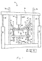
- Figures 1 and 2 show an embodiment of the apparatus 10 of the invention for determining if a brush seal 12 (whether new or used) is defective. If the apparatus 10 does not determine that the brush seal 12 is defective, the brush seal 12 is suitable for initial or continued use. If the apparatus 10 determines that the brush seal 12 is defective, the brush seal 12 is sent to the scrap pile or the recycle bin. As will be appreciated by the artisan, the apparatus 10 measures the stiffness of the brush seal 12.
- the brush seal 12 shown in Figure 1 is an annular brush seal which has the shape of a partially-circular ring. Typically, several such segments are circumferentially-arrayed to form a completely-circular ring.
- the apparatus 10 can accept or be modified to accept a brush seal which has an arbitrary shape including, without limitation, a completely-circular ring shape, a partially or completely-elliptical ring shape, or a rectilinear shape. It is noted that the apparatus 10 can be modified to test installed brush seals to determine if they are defective. Brush seals are used in many applications including, without limitation, gas and steam turbines for power generation and gas turbines for aircraft propulsion.
- the brush seal 12 has a support plate 14 and a set of bristles 16.
- the set of bristles 16 is defined to be all of the bristles 16 of the brush seal 12.
- the bristles 16 each have a free end 18 and an attached end 20.
- the attached end 20 is secured to the support plate 14.
- the support plate may be shaped to include a backing plate portion and/or an upstream plate portion as is known to the artisan. Such backing and upstream plate portions, which have been omitted from the figures for clarity, may be separate plates attached to the support plate 14.
- the annular brush seal 12 of Figure 1 has an arc length extending from the left-most bristles 22 to the right-most bristles 24.
- the bristles 16 have a bristle length extending from the attached end 20 to the free end 18, and that the brush seal 12 has a thickness which extends into the page of Figure 1.
- the bristles 16 are metal wire bristles whose attached ends 20 are welded to the support plate 14. It is noted that the invention is not limited to metal and/or wire bristles.
- Apparatus 10 includes a load transducer 26 which includes a contact head 28 which is sized to contact less than twenty percent of the bristles 16 of the set of bristles 16 when the contact head 28 and the free ends 18 of the bristles 16 are brought into contact.
- the load transducer 26 measures the force exerted by the contacted bristles 16 on the contact head 28.
- the load transducer 26 is shown attached to a movable bar 30 whose height on the support rods 32 can be adjusted by the pistons 34 of the powered cylinders 36.
- the contact head 28 is sized to contact less than ten percent of the bristles 16 of the set of bristles 16 when the contact head 28 and the free ends 18 of the bristles 16 are brought into contact, and in another exemplary embodiment, the contact head 28 is sized to contact less than five percent of the bristles 16 of the set of bristles 16 when the contact head 28 and the free ends 18 of the bristles 16 are brought into contact. In one example, the contact head 28 is sized to contact generally two and one-half percent of the bristles 16 of the set of bristles 16 when the contact head 28 and the free ends 18 of the bristles 16 are brought into contact.
- the contact head 28 is sized to contact the bristles 16 along less than twenty, ten, or five percent of the arc length when the contact head 28 and the free ends 18 of the bristles 16 are brought into contact
- a smaller size of the contact head 28 means a greater number of independent bristle locations that can be measured.
- the contact head 28 has a radius which matches the radius of the free ends 18 of the set of bristles 16.
- Apparatus 10 also includes a clamp 40 for securing the brush seal 12.
- the clamp 40 is disposed to present the free ends 18 of a portion of the bristles 16 of the set of bristles 16 to the contact head 28 of the load transducer 26.
- apparatus 10 also includes a displacement transducer 42 which is disposed to measure the displacement of the free ends 18 of the bristles 16 when the contact head 28 and the free ends 18 of the bristles 16 are brought into contact.
- apparatus 10 also includes a linear positioner 44 having a piston 46.
- the piston 46 is attached to the clamp 40 and moves the clamp 40 such that the free ends 18 of the previously-described portion of the bristles 16 of the secured brush seal 12 are brought into contact with the contact head 28 of the load transducer 26.
- the linear positioner 44 includes the previously-described displacement transducer 42 which measures the displacement of the free ends 18 of the bristles 16 when the contact head 28 and the free ends 18 of the bristles 16 are brought into contact.
- apparatus 10 can be modified to test installed brush seals once other components (such as rotors) have been removed to provide proper access to the bristles.
- the displacement transducer 42 also can be used to measure bristle wear of contacted bristles at various bristle locations by measuring the distance to initial bristle contact from a reference point.
- the clamp 40 includes a base plate 48 with a slot 50 (shown in Figure 2) and also includes two spaced-apart first and second seal holders 52 and 54 for contacting and supporting the brush seal 12.
- the first and second seal holders 52 and 54 are movable in the slot 50 and are securable to the base plate 48.
- the clamp 40 also includes a threaded bolt 56 having a first end 58 and a second end 60.
- the threaded bolt 56 is rotatable to different heights above the base plate 48 and is secured to the base plate 48.
- the threaded bolt 56 is secured to the first seal holder 52 proximate the first end 58. It is noted that a threaded bolt 56 is provided for each seal holder 52 and 54.
- the clamp 40 additionally includes a first nut 62 threaded onto the threaded bolt 56 above and in contact with the base plate 48 and includes a second nut 64 threaded onto the threaded bolt 56 below and in contact with the base plate 40.
- the threaded bolt 56 has a longitudinal axis 66
- the slot 50 has a lengthwise axis 68
- the first seal holder 52 is rotatable about an axis 70 which is perpendicular to both the longitudinal axis 66 of the threaded bolt 56 and the lengthwise axis 68 of the slot 50 of the base plate 48.
- the clamp 40 allows the first and second seal holders 52 and 54 independently to be set at an arbitrary distance along the longitudinal axis 66 and an arbitrary distance along the lengthwise axis 68 and independently to be set at an arbitrary angular orientation about the axis 70 (which typically is a bolt) thus allowing the bristles 16 of any area of the brush seal 12 to be presented to the contact head 28 of the load transducer 26.
- Step 3 shows an embodiment of the method of the invention for determining if a brush seal 12 is defective, wherein the brush seal has a set of bristles 16.
- the method includes steps a), b), and c).
- Step a) is shown in block 72 of Figure 3 as ""Empirically Determine Stiffness Of Different Subsets Of Bristles".
- Step a) includes empirically determining a stiffness value for each of a plurality of different subsets of the set of bristles 16. An empirically-determined stiffness value will depend on a measured force exerted on the bristles and a measured deflection of the bristles caused by that force.
- stiffness value equals the measured force (or pressure, i.e., the force per unit area of the contact head 28) for a prechosen measured deflection divided by the diameter of a bristle.
- stiffness value equals the measured force (or pressure, i.e., the force per unit area of the contact head 28) for a prechosen measured deflection divided by the cross-sectional area of the involved bristles.
- Other definitions utilizing force and deflection may be chosen by the artisan.
- a bristle 16 of one subset belongs only to that subset, and, for an annular brush seal 12, different subsets are disposed at different locations along the arc length of the brush seal.
- step a) includes empirically determining a stiffness value for each of at least five completely different subsets of the set of bristles 16 along the arc length of the annular brush seal 12.
- step a) includes empirically determining a stiffness value for each of at least ten completely different subsets of the set of bristles 16 along the arc length of the brush seal 12.
- Step b) is shown in block 74 of Figure 3 as "Calculate Variation In Stiffness".
- Step b) includes calculating a variation in stiffness based on the stiffness values empirically determined in step a).
- the variation in stiffness is calculated for each subset and is equal to the absolute value of the difference between the stiffness value of the subset and the average of the stiffness values of all the empirically-determined subsets.
- the average is defined to be the mean value. Other definitions of variation and/or average may be chosen by the artisan.
- Step c) is shown in block 76 of Figure 3 as "Identify As Defective If Variation Exceeds Predetermined Criteria".
- Step c) includes identifying the brush seal 12 as defective if the variation in stiffness calculated in step b) exceeds a predetermined stiffness-variation criteria.
- a predetermined stiffness-variation criteria is that a brush seal 12 is identified as being defective if the absolute value of the variation in stiffness calculated in step b) for any subset exceeds twenty-five percent of the average (e.g., the mean) of the stiffness values empirically determined in step a).
- a brush seal 12 is identified as being defective if the absolute value of the variation in stiffness calculated in step b) for any subset exceeds ten percent of the average of the stiffness values empirically determined in step a).
- Other criteria may identify a brush seal 12 as defective if at least two (or some other number) or at least ten percent (or some other percent) of the subsets have stiffness-variations exceeding , say, some percentage of the average bristle stiffness of the empirically-determined subsets.
- Applicants measured stiffness variations of generally three hundred percent in early-worn seals and recognized that such a large stiffness variation was the cause of the brush-seal early-wear problem. For such measurements, Applicants used an MTS Model 810 Material Test System which integrated the load transducer 26, displacement transducer 42, and linear positioner 44 in a single machine.
- the apparatus of the invention may also be described as including means for empirically determining a stiffness value for each of a plurality of different subsets of the set of bristles 16, means for calculating a variation in stiffness based on the stiffness values empirically determined by the empirically-determining means, and means for identifying the brush seal 12 as defective if the variation in stiffness calculated by the calculating means exceeds a predetermined stiffness-variation criteria.
- the empirically-determining means is the previously-described apparatus 10 of Figures 1 and 2 with the addition of a computer 78 which determines (or a technician who mathematically determines) a stiffness value from the output 80 of the load transducer 26 and the output 82 of the displacement transducer 42.
- the empirically-determining means includes portable apparatus to empirically determine bristle stiffness of an installed brush seal, such portable apparatus being attachable to suitable structure on or proximate the installed brush seal.
- a bristle of one subset belongs only to that subset, and, for an annular brush seal 12, different subsets are disposed at different locations along the arc length of the annular brush seal 12.
- the empirically-determining means determines a stiffness value for each of at least five completely different subsets of the set of bristles 16 along the arc length of the brush seal 12.
- a more detailed map of stiffness variation is obtained, in another example, wherein the empirically-determining means determines a stiffness value for each of at least ten completely different subsets of the set of bristles 16 along the arc length of the annular brush seal 12.
- the calculating means includes a computer, such as the previously-described computer 78, which calculates the variation in stiffness for each subset from the output 80 of the load transducer 26 and the output 82 of the displacement transducer 42.
- the calculating means includes a technician who mathematically determines stiffness from the load transducer 26 and the displacement transducer 42.
- the identifying means includes a computer, such as the previously-described computer 78, which stores the predetermined stiffness variation criteria and which compares the calculated variation in stiffness with the stored criteria.
- the identifying means includes a technician who mathematically (or visually on a graph) compares the calculated variation in stiffness with the predetermined stiffness variation criteria.
- the identifying means identifies the annular brush seal 12 as defective if the absolute value of the variation in stiffness calculated by the calculating means for any subset exceeds twenty-five percent (or exceeds ten percent in more demanding applications) of the average of the stiffness values empirically determined by the empirically-determining means.
- a brush seal having a large variation in bristle stiffness among different bristles is a defective brush seal which will have its more stiff bristles wear faster than its less stiff bristles. Such uneven wear develops quickly for a large variation in bristle stiffness and can render the brush seal unfit for proper sealing soon after installation.
- a loss of a million dollars a year can result from using worn-out brush seals.
- Applicant's method and apparatus determines if a brush seal is an early-wearing brush seal before it is installed so that only long-lasting brush seals are actually installed and used.
Landscapes
- Engineering & Computer Science (AREA)
- General Engineering & Computer Science (AREA)
- Mechanical Engineering (AREA)
- Sealing Devices (AREA)
- Testing Of Devices, Machine Parts, Or Other Structures Thereof (AREA)
- Length Measuring Devices With Unspecified Measuring Means (AREA)
Applications Claiming Priority (2)
| Application Number | Priority Date | Filing Date | Title |
|---|---|---|---|
| US252386 | 1999-02-18 | ||
| US09/252,386 US6435011B1 (en) | 1999-02-18 | 1999-02-18 | Method and apparatus for determining if brush seals are defective |
Publications (2)
| Publication Number | Publication Date |
|---|---|
| EP1030084A2 true EP1030084A2 (de) | 2000-08-23 |
| EP1030084A3 EP1030084A3 (de) | 2004-01-07 |
Family
ID=22955803
Family Applications (1)
| Application Number | Title | Priority Date | Filing Date |
|---|---|---|---|
| EP00301214A Withdrawn EP1030084A3 (de) | 1999-02-18 | 2000-02-16 | Verfahren und Vorrichtung zur Prüfung einer Bürstendichtung |
Country Status (3)
| Country | Link |
|---|---|
| US (1) | US6435011B1 (de) |
| EP (1) | EP1030084A3 (de) |
| JP (1) | JP2000249627A (de) |
Cited By (1)
| Publication number | Priority date | Publication date | Assignee | Title |
|---|---|---|---|---|
| CN110987420A (zh) * | 2019-12-25 | 2020-04-10 | 中国航空工业集团公司西安飞机设计研究所 | 一种操纵力及操纵位移检测方法 |
Families Citing this family (6)
| Publication number | Priority date | Publication date | Assignee | Title |
|---|---|---|---|---|
| US6854735B2 (en) * | 2002-08-26 | 2005-02-15 | General Electric Company | In situ load sharing brush seals |
| JP5265497B2 (ja) * | 2009-10-29 | 2013-08-14 | オリンパスメディカルシステムズ株式会社 | ブラシ寿命検知装置及び内視鏡洗浄装置 |
| JP6115990B2 (ja) * | 2013-02-28 | 2017-04-19 | 株式会社 エイブル | タービンロータ翼植込部のカシメ部の内部応力除去方法およびカシメ部加熱装置 |
| CN105547611B (zh) * | 2016-01-20 | 2018-03-09 | 昆山众备机械设备有限公司 | 盾构机盾尾刷密封耐压测试设备 |
| CN106768710B (zh) * | 2017-03-29 | 2019-09-27 | 中国航发沈阳发动机研究所 | 一种多级刷式密封试验方法 |
| US10832395B2 (en) * | 2019-03-25 | 2020-11-10 | Raytheon Technologies Corporation | Systems and methods for inspecting bristles using a digital camera |
Family Cites Families (10)
| Publication number | Priority date | Publication date | Assignee | Title |
|---|---|---|---|---|
| US3165926A (en) * | 1961-06-29 | 1965-01-19 | Toledo Scale Corp | Control circuit for spring testers and the like |
| GB1450553A (en) * | 1973-11-23 | 1976-09-22 | Rolls Royce | Seals and a method of manufacture thereof |
| GB2062168B (en) * | 1979-10-20 | 1983-06-29 | Mhh Eng Co Ltd | Spring testing machines |
| US5088333A (en) * | 1989-10-27 | 1992-02-18 | John Kiely | System for testing elastic components and methods of using same |
| US5758879A (en) * | 1991-08-01 | 1998-06-02 | Cross Manufacturing Company (1938) Limited | Brush seal assembly |
| US5168761A (en) * | 1991-09-09 | 1992-12-08 | B&W Nuclear Service Company | Automated spring pack testing method |
| US5438863A (en) * | 1993-05-03 | 1995-08-08 | The B. F. Goodrich Company | Universal material test system and method |
| US5922968A (en) * | 1995-09-06 | 1999-07-13 | Briscoe; William Anthony | Brush pressure system |
| DE19641375C1 (de) * | 1996-10-08 | 1997-12-04 | Mtu Muenchen Gmbh | Herstellungsverfahren für und Vorrichtung zum Herstellen von Bürstendichtungen |
| GB2322168B (en) * | 1997-02-18 | 2001-02-14 | Europ Gas Turbines Ltd | Brush seal and method for the manufacture of a brush seal |
-
1999
- 1999-02-18 US US09/252,386 patent/US6435011B1/en not_active Expired - Fee Related
-
2000
- 2000-02-16 EP EP00301214A patent/EP1030084A3/de not_active Withdrawn
- 2000-02-18 JP JP2000040526A patent/JP2000249627A/ja not_active Withdrawn
Non-Patent Citations (1)
| Title |
|---|
| None |
Cited By (2)
| Publication number | Priority date | Publication date | Assignee | Title |
|---|---|---|---|---|
| CN110987420A (zh) * | 2019-12-25 | 2020-04-10 | 中国航空工业集团公司西安飞机设计研究所 | 一种操纵力及操纵位移检测方法 |
| CN110987420B (zh) * | 2019-12-25 | 2021-11-02 | 中国航空工业集团公司西安飞机设计研究所 | 一种操纵力及操纵位移检测方法 |
Also Published As
| Publication number | Publication date |
|---|---|
| JP2000249627A (ja) | 2000-09-14 |
| EP1030084A3 (de) | 2004-01-07 |
| US6435011B1 (en) | 2002-08-20 |
Similar Documents
| Publication | Publication Date | Title |
|---|---|---|
| US6435011B1 (en) | Method and apparatus for determining if brush seals are defective | |
| US8102539B2 (en) | Method for measuring a gap between a multibladed rotatable member and a surrounding housing | |
| EP2294358B1 (de) | Vorrichtung und verfahren zur messung der erosion einer kante einer turbomaschinentragfläche | |
| US6260269B1 (en) | Method for overhauling a steam turbine to increase its power | |
| EP0989342A2 (de) | Hybriddichtung und Kreiselmaschine mit einer solchen Dichtung | |
| US6854735B2 (en) | In situ load sharing brush seals | |
| EP0979963B1 (de) | Bürstendichtungssegment | |
| US8820148B2 (en) | External casing functional access port | |
| EP2163734A2 (de) | Vorrichtung zur Befestigung von Gasturbinenleitschaufel | |
| US6612581B2 (en) | Brush seal coil for rotary machinery and method of retrofitting | |
| CA2205877A1 (en) | Brush seals and combined labyrinth and brush seals for rotary machines | |
| US5961125A (en) | Brush seal for use on rough rotating surfaces | |
| CN105649685A (zh) | 一种刷丝束可径向调节的组合式刷式密封结构 | |
| US20060064988A1 (en) | Turbine power plant having minimal-contact brush seal augmented labyrinth seal | |
| EP2602432A1 (de) | Vorrichtung und Verfahren zur Formung von Turbinenschaufelabdeckplatten | |
| KR20230120982A (ko) | T-페어링 설치 툴링 조립체 | |
| WO2003058362A1 (en) | Method and apparatus for assessing the impact of individual parts of a gas turbine component on the overall thermal performance of a gas turbine | |
| CN118031767B (zh) | 航空发动机叶片叶尖磨损深度检测装置 | |
| US11208908B2 (en) | Static seal arrangement and turbomachine | |
| US6618693B2 (en) | Method and apparatus for non-intrusive monitoring of rotating components | |
| Stephen et al. | Development of brush seal technology for steam turbine retrofit applications | |
| US20150308284A1 (en) | Apparatus and method for inspecting a turbine blade tip shroud | |
| CN113125158B (zh) | 固定被检测的带冠叶片的装置和带冠叶片检测设备 | |
| CN1328479C (zh) | 涡轮机和确定其动/静叶片的电绝缘表面受损情况的方法 | |
| US20070273103A1 (en) | Sealing Device |
Legal Events
| Date | Code | Title | Description |
|---|---|---|---|
| PUAI | Public reference made under article 153(3) epc to a published international application that has entered the european phase |
Free format text: ORIGINAL CODE: 0009012 |
|
| AK | Designated contracting states |
Kind code of ref document: A2 Designated state(s): AT BE CH CY DE DK ES FI FR GB GR IE IT LI LU MC NL PT SE |
|
| AX | Request for extension of the european patent |
Free format text: AL;LT;LV;MK;RO;SI |
|
| PUAL | Search report despatched |
Free format text: ORIGINAL CODE: 0009013 |
|
| AK | Designated contracting states |
Kind code of ref document: A3 Designated state(s): AT BE CH CY DE DK ES FI FR GB GR IE IT LI LU MC NL PT SE |
|
| AX | Request for extension of the european patent |
Extension state: AL LT LV MK RO SI |
|
| 17P | Request for examination filed |
Effective date: 20040707 |
|
| AKX | Designation fees paid |
Designated state(s): DE FR GB IT |
|
| 17Q | First examination report despatched |
Effective date: 20041112 |
|
| GRAP | Despatch of communication of intention to grant a patent |
Free format text: ORIGINAL CODE: EPIDOSNIGR1 |
|
| STAA | Information on the status of an ep patent application or granted ep patent |
Free format text: STATUS: THE APPLICATION IS DEEMED TO BE WITHDRAWN |
|
| 18D | Application deemed to be withdrawn |
Effective date: 20060810 |