EP1030080A2 - Infinite speed ratio transmission device and assembly method thereof - Google Patents
Infinite speed ratio transmission device and assembly method thereof Download PDFInfo
- Publication number
- EP1030080A2 EP1030080A2 EP00102432A EP00102432A EP1030080A2 EP 1030080 A2 EP1030080 A2 EP 1030080A2 EP 00102432 A EP00102432 A EP 00102432A EP 00102432 A EP00102432 A EP 00102432A EP 1030080 A2 EP1030080 A2 EP 1030080A2
- Authority
- EP
- European Patent Office
- Prior art keywords
- output
- casing
- sprocket
- upper link
- disk
- Prior art date
- Legal status (The legal status is an assumption and is not a legal conclusion. Google has not performed a legal analysis and makes no representation as to the accuracy of the status listed.)
- Withdrawn
Links
- 230000005540 biological transmission Effects 0.000 title claims description 64
- 238000000034 method Methods 0.000 title claims description 15
- 238000005192 partition Methods 0.000 claims description 36
- 230000002452 interceptive effect Effects 0.000 claims description 2
- 238000010276 construction Methods 0.000 description 6
- 230000007423 decrease Effects 0.000 description 1
- 238000010586 diagram Methods 0.000 description 1
- 238000003780 insertion Methods 0.000 description 1
- 230000037431 insertion Effects 0.000 description 1
- 238000009434 installation Methods 0.000 description 1
- 238000012986 modification Methods 0.000 description 1
- 230000004048 modification Effects 0.000 description 1
- 230000007935 neutral effect Effects 0.000 description 1
Images




Classifications
-
- F—MECHANICAL ENGINEERING; LIGHTING; HEATING; WEAPONS; BLASTING
- F16—ENGINEERING ELEMENTS AND UNITS; GENERAL MEASURES FOR PRODUCING AND MAINTAINING EFFECTIVE FUNCTIONING OF MACHINES OR INSTALLATIONS; THERMAL INSULATION IN GENERAL
- F16H—GEARING
- F16H15/00—Gearings for conveying rotary motion with variable gear ratio, or for reversing rotary motion, by friction between rotary members
- F16H15/02—Gearings for conveying rotary motion with variable gear ratio, or for reversing rotary motion, by friction between rotary members without members having orbital motion
- F16H15/04—Gearings providing a continuous range of gear ratios
- F16H15/06—Gearings providing a continuous range of gear ratios in which a member A of uniform effective diameter mounted on a shaft may co-operate with different parts of a member B
- F16H15/32—Gearings providing a continuous range of gear ratios in which a member A of uniform effective diameter mounted on a shaft may co-operate with different parts of a member B in which the member B has a curved friction surface formed as a surface of a body of revolution generated by a curve which is neither a circular arc centered on its axis of revolution nor a straight line
- F16H15/36—Gearings providing a continuous range of gear ratios in which a member A of uniform effective diameter mounted on a shaft may co-operate with different parts of a member B in which the member B has a curved friction surface formed as a surface of a body of revolution generated by a curve which is neither a circular arc centered on its axis of revolution nor a straight line with concave friction surface, e.g. a hollow toroid surface
- F16H15/38—Gearings providing a continuous range of gear ratios in which a member A of uniform effective diameter mounted on a shaft may co-operate with different parts of a member B in which the member B has a curved friction surface formed as a surface of a body of revolution generated by a curve which is neither a circular arc centered on its axis of revolution nor a straight line with concave friction surface, e.g. a hollow toroid surface with two members B having hollow toroid surfaces opposite to each other, the member or members A being adjustably mounted between the surfaces
-
- F—MECHANICAL ENGINEERING; LIGHTING; HEATING; WEAPONS; BLASTING
- F16—ENGINEERING ELEMENTS AND UNITS; GENERAL MEASURES FOR PRODUCING AND MAINTAINING EFFECTIVE FUNCTIONING OF MACHINES OR INSTALLATIONS; THERMAL INSULATION IN GENERAL
- F16H—GEARING
- F16H3/00—Toothed gearings for conveying rotary motion with variable gear ratio or for reversing rotary motion
- F16H3/44—Toothed gearings for conveying rotary motion with variable gear ratio or for reversing rotary motion using gears having orbital motion
-
- F—MECHANICAL ENGINEERING; LIGHTING; HEATING; WEAPONS; BLASTING
- F16—ENGINEERING ELEMENTS AND UNITS; GENERAL MEASURES FOR PRODUCING AND MAINTAINING EFFECTIVE FUNCTIONING OF MACHINES OR INSTALLATIONS; THERMAL INSULATION IN GENERAL
- F16H—GEARING
- F16H37/00—Combinations of mechanical gearings, not provided for in groups F16H1/00 - F16H35/00
- F16H37/02—Combinations of mechanical gearings, not provided for in groups F16H1/00 - F16H35/00 comprising essentially only toothed or friction gearings
- F16H37/06—Combinations of mechanical gearings, not provided for in groups F16H1/00 - F16H35/00 comprising essentially only toothed or friction gearings with a plurality of driving or driven shafts; with arrangements for dividing torque between two or more intermediate shafts
- F16H37/08—Combinations of mechanical gearings, not provided for in groups F16H1/00 - F16H35/00 comprising essentially only toothed or friction gearings with a plurality of driving or driven shafts; with arrangements for dividing torque between two or more intermediate shafts with differential gearing
- F16H37/0833—Combinations of mechanical gearings, not provided for in groups F16H1/00 - F16H35/00 comprising essentially only toothed or friction gearings with a plurality of driving or driven shafts; with arrangements for dividing torque between two or more intermediate shafts with differential gearing with arrangements for dividing torque between two or more intermediate shafts, i.e. with two or more internal power paths
- F16H37/084—Combinations of mechanical gearings, not provided for in groups F16H1/00 - F16H35/00 comprising essentially only toothed or friction gearings with a plurality of driving or driven shafts; with arrangements for dividing torque between two or more intermediate shafts with differential gearing with arrangements for dividing torque between two or more intermediate shafts, i.e. with two or more internal power paths at least one power path being a continuously variable transmission, i.e. CVT
- F16H37/086—CVT using two coaxial friction members cooperating with at least one intermediate friction member
-
- F—MECHANICAL ENGINEERING; LIGHTING; HEATING; WEAPONS; BLASTING
- F16—ENGINEERING ELEMENTS AND UNITS; GENERAL MEASURES FOR PRODUCING AND MAINTAINING EFFECTIVE FUNCTIONING OF MACHINES OR INSTALLATIONS; THERMAL INSULATION IN GENERAL
- F16H—GEARING
- F16H37/00—Combinations of mechanical gearings, not provided for in groups F16H1/00 - F16H35/00
- F16H37/02—Combinations of mechanical gearings, not provided for in groups F16H1/00 - F16H35/00 comprising essentially only toothed or friction gearings
- F16H37/06—Combinations of mechanical gearings, not provided for in groups F16H1/00 - F16H35/00 comprising essentially only toothed or friction gearings with a plurality of driving or driven shafts; with arrangements for dividing torque between two or more intermediate shafts
- F16H37/08—Combinations of mechanical gearings, not provided for in groups F16H1/00 - F16H35/00 comprising essentially only toothed or friction gearings with a plurality of driving or driven shafts; with arrangements for dividing torque between two or more intermediate shafts with differential gearing
- F16H37/0833—Combinations of mechanical gearings, not provided for in groups F16H1/00 - F16H35/00 comprising essentially only toothed or friction gearings with a plurality of driving or driven shafts; with arrangements for dividing torque between two or more intermediate shafts with differential gearing with arrangements for dividing torque between two or more intermediate shafts, i.e. with two or more internal power paths
- F16H37/084—Combinations of mechanical gearings, not provided for in groups F16H1/00 - F16H35/00 comprising essentially only toothed or friction gearings with a plurality of driving or driven shafts; with arrangements for dividing torque between two or more intermediate shafts with differential gearing with arrangements for dividing torque between two or more intermediate shafts, i.e. with two or more internal power paths at least one power path being a continuously variable transmission, i.e. CVT
- F16H2037/088—Power-split transmissions with summing differentials, with the input of the CVT connected or connectable to the input shaft
-
- F—MECHANICAL ENGINEERING; LIGHTING; HEATING; WEAPONS; BLASTING
- F16—ENGINEERING ELEMENTS AND UNITS; GENERAL MEASURES FOR PRODUCING AND MAINTAINING EFFECTIVE FUNCTIONING OF MACHINES OR INSTALLATIONS; THERMAL INSULATION IN GENERAL
- F16H—GEARING
- F16H37/00—Combinations of mechanical gearings, not provided for in groups F16H1/00 - F16H35/00
- F16H37/02—Combinations of mechanical gearings, not provided for in groups F16H1/00 - F16H35/00 comprising essentially only toothed or friction gearings
- F16H37/06—Combinations of mechanical gearings, not provided for in groups F16H1/00 - F16H35/00 comprising essentially only toothed or friction gearings with a plurality of driving or driven shafts; with arrangements for dividing torque between two or more intermediate shafts
- F16H37/08—Combinations of mechanical gearings, not provided for in groups F16H1/00 - F16H35/00 comprising essentially only toothed or friction gearings with a plurality of driving or driven shafts; with arrangements for dividing torque between two or more intermediate shafts with differential gearing
- F16H37/0833—Combinations of mechanical gearings, not provided for in groups F16H1/00 - F16H35/00 comprising essentially only toothed or friction gearings with a plurality of driving or driven shafts; with arrangements for dividing torque between two or more intermediate shafts with differential gearing with arrangements for dividing torque between two or more intermediate shafts, i.e. with two or more internal power paths
- F16H37/084—Combinations of mechanical gearings, not provided for in groups F16H1/00 - F16H35/00 comprising essentially only toothed or friction gearings with a plurality of driving or driven shafts; with arrangements for dividing torque between two or more intermediate shafts with differential gearing with arrangements for dividing torque between two or more intermediate shafts, i.e. with two or more internal power paths at least one power path being a continuously variable transmission, i.e. CVT
- F16H2037/088—Power-split transmissions with summing differentials, with the input of the CVT connected or connectable to the input shaft
- F16H2037/0886—Power-split transmissions with summing differentials, with the input of the CVT connected or connectable to the input shaft with switching means, e.g. to change ranges
Definitions
- This invention relates to an infinite speed ratio transmission device for vehicles comprising a toroidal continuously variable transmission, a fixed speed ratio transmission and a planetary gear set.
- a direct drive mode wherein the direct mode clutch is engaged and the power circulation mode clutch is disengaged
- a power circulation mode wherein the direct mode clutch is disengaged and the power circulation mode clutch is engaged.
- the direct drive mode the engine output is transmitted to the drive shaft via the CVT.
- the power circulation mode the rotation of the ring gear stops at a position where the rotation of the sun gear due to the output of the fixed speed ratio transmission and the rotation of the planet carrier due to the output of the CVT are balanced. This state corresponds to a neutral state where rotation torque is not transmitted to the drive shaft. In this case, the ratio of the engine speed and the rotation speed of the final output shaft becomes infinite.
- Tokkai Hei 9-317837 published by the Japanese Patent Office in 1997 discloses an upper link and lower link for displacing trunnions facing each other with opposite phase in the axial direction.
- the upper link is supported by a post fixed to a casing via a pin.
- Some infinite speed ratio transmission devices transmit the output of the CVT to the sun gear via a pair of sprockets and a chain.
- the upper link attached to the casing interferes with the chain when assembling the transmission device.
- one sprocket is situated between a pair of output disks, and if the upper links situated on both sides in the axial direction of the sprocket are previously attached to the casing, the chain cannot be looped around the sprocket.
- this invention provides an infinite speed ratio transmission device for a vehicle, comprising an input shaft, a first toroidal unit comprising a first input disk which rotates together with the input shaft, a first output disk, and two power rollers gripped between the first input disk and the first output disk, a second toroidal unit comprising a second input disk which rotates together with the input shaft, a second output disk, and two power rollers gripped between the second input disk and the second output disk, the first output disk and the second output disk being disposed coaxially and adjacent to each other, an output sprocket which is disposed between and rotates together with the first output disk and the second output disk, four trunnions which support the four power rollers of the first toroidal unit and the second toroidal unit, an upper link holding the upper end of the four trunnions, the upper link comprising a first part holding the two trunnions of the first toroidal unit, and a second part holding the two trunnions of the second
- This invention also provides an assembly method of the above infinite speed ratio transmission device.
- the method comprises fixing the second upper link supporting member to the casing, fitting the second part to the second upper link supporting member, setting the output sprocket at a predetermined position in the casing, inserting the sprocket around which the chain has been looped and the planetary gear unit in the casing, looping the chain around the output sprocket, setting the sprocket and the planetary gear unit at a predetermined position in the casing, fixing the first upper link supporting member to the casing, fitting the first part to the first upper link supporting member, and joining the first part to the second part.
- This invention also provides an assembly method comprising fixing the second upper link supporting member to the casing, fitting the second part to the second upper link supporting member, looping the chain around the output sprocket and the sprocket, fitting the intermediate wall on the output sprocket, setting the output sprocket on which the intermediate wall is fitted and the planetary gear set in which the sprocket is combined with the output sprocket via the chain, at a predetermined position in the casing, fixing the first upper link supporting member to the casing fitting the first part to the first upper link supporting member, and joining the first part to the second part.
- This invention also provides an assembly method of the infinite speed ratio transmission device in which the intermediate wall further comprise a front partition disposed between the first output disk and the output sprocket, a rear partition disposed between the second output disk and the output sprocket, and a fixing member which fixes the front partition to the rear partition.
- the method comprises fixing the second upper link supporting member to the casing, fitting the second part to the second upper link supporting member, setting the output sprocket at a predetermined position in the casing together with the rear partition, inserting the sprocket around which the chain has been looped and the planetary gear unit in the casing, looping the chain around the output sprocket, setting the sprocket and the planetary gear unit at a predetermined position in the casing, fixing the front partition to the rear partition by the fixing member, fixing the first upper link supporting member to the casing, fitting the first part to the first upper link supporting member, and joining the first part to the second part.
- Fig. 1 is a schematic diagram of an infinite speed ratio transmission device according to this invention.
- Fig. 2 is a vertical sectional view of the infinite speed ratio transmission device.
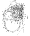
- Fig. 3 is a horizontal sectional view of a toroidal continuously variable transmission according to this invention.
- Fig. 4 is a schematic plan view of essential parts of the infinite speed ratio transmission device showing the disposition of an intermediate wall and an upper link supporting member, according to this invention.
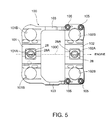
- Fig. 5 is a plan view of the upper link according to this invention.
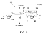
- Fig. 6 is a side view of the upper link.
- Fig. 7 is a plan view of the toroidal continuously variable transmission viewed from underneath.
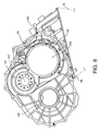
- Fig. 8 is a side view of a casing according to this invention.
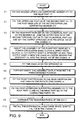
- Fig. 9 is a flow chart describing the process of assembling the infinite speed ratio transmission device according to this invention.
- an infinite speed ratio transmission device for a vehicle comprises an input shaft 1, a toroidal continuously variable transmission (CVT) 2, a fixed speed ratio transmission 3, planetary gear set 5 and final output shaft 6.
- the CVT 2 comprises a half toroidal type first toroidal unit 2A and second toroidal unit 2B.
- Each of the toroidal units 2A, 2B comprise an input disk 21 and output disk 22, respectively.
- a pair of power rollers 20 are gripped between the input disk 21 and output disk 22.
- the input disks 21 rotate together with the input shaft 1.
- the input shaft 1 is joined to an engine output shaft, not shown.
- the output disk 22 of the first toroidal unit 2A is joined to the output disk 22 of the second toroidal unit 2B, and the output disks rotate together with an output sprocket 24 disposed between the output disks 22.
- the rotation of the output sprocket 24 is transmitted to a CVT output shaft 4 via a chain 40 and sprocket 4A.
- the CVT output shaft 4 is joined to a sun gear 5A of the planetary gear set 5, and is also joined to a final output shaft 6 via a direct clutch 10.
- the fixed speed ratio transmission 3 comprises an input gear 3A which rotates together with the input shaft 1, output gear 3B and gear output shaft 3C.
- the input gear 3A is meshed with the output gear 3B, and the output gear 3B is joined to the gear output shaft 3C.
- the gear output shaft 3C is joined to a planet carrier 5B holding a plurality of planet gears of the planetary gear set 5 via a power circulation mode clutch 9.
- a ring gear 5C of the planetary gear unit 5 is joined to the final output shaft 6.
- the rotation of the final output shaft 6 is transmitted to drive wheel shafts 11A, 11B of the vehicle via a transmission output gear 7, final gear 12 and differential 8.
- the drive wheel shafts 11A, 11B are driven by either of two transmission modes, i.e., a power circulation mode wherein the power circulation mode clutch 9 is engaged and the direct mode clutch 10 is disengaged, and a direct mode wherein the power circulation mode clutch 9 is disengaged and the direct mode clutch 10 is engaged.
- a power circulation mode wherein the power circulation mode clutch 9 is engaged and the direct mode clutch 10 is disengaged
- a direct mode wherein the power circulation mode clutch 9 is disengaged and the direct mode clutch 10 is engaged.
- the rotation speed of the final output shaft 6 can be continuously varied from a negative value to a positive value according to the difference of the speed ratios of the CVT 2 and the fixed speed ratio transmission 3.
- the input shaft 1 comprises the shafts 1A, 1B which are disposed coaxially and rotate together via loading cams 23.
- the shaft 1A is joined to a crankshaft 13 of an engine of the vehicle.
- a flywheel 13A is attached to the crankshaft 13.
- An input gear 3A of the fixed speed ratio transmission 3 is fixed to the shaft 1A.
- This infinite speed ratio transmission device is disposed in an engine room of the vehicle such that the input shaft 1 makes a right angle with the vehicle forward motion direction.
- the upward direction in the figure corresponds to the direction of the vehicle forward motion.
- the shaft 1B is joined to the pair of input disks 21.
- a thrust force generated by the loading cams 23 makes the shaft 1A and shaft 1B rotate together via the input disks 21 of the first toroidal unit 2A as the shaft 1A rotates. Further, in the first toroidal unit 2A and second toroidal unit 2B, this thrust force presses the input disk 21 toward the output disk 2. Due to this pressing force, the power rollers 20 shown in Fig. 3 gripped by the input disk 21 and output disk 22 transmit a torque from one disk to the other disk.
- the inside of a casing 14 of the infinite speed ratio transmission device comprises a space 14X which houses the CVT 2 and the input gear 3A of the fixed speed ratio transmission 3, and an effectively cylindrical space 14Y which houses the sprocket 4A, CVT output shaft 4, planetary gear set 5, final output shaft 6 and output gear 3B of the fixed speed ratio transmission 3.
- These spaces 14X, 14Y are interconnected.
- One end of the space 14X reaches an edge 14A of the casing 14 in Fig. 2 on the right-hand side of the figure, and the other end reaches an edge 14B of the casing 14 on the left-hand side of the figure.
- the edge 14A is closed by a partition 15A
- the edge 14B is closed by a side cover 16.
- the partition 15A forms part of a front casing 15 which joins the casing 14 to the engine, not shown.
- the edge of the space 14Y on the left-hand side of the figure is closed by a side cover 60.
- the edge 14A of the casing 14 has an opening 140 for installing the input shaft 1 and CVT 2 in the space 14X when the infinite speed ratio transmission device is assembled, an opening 141 for installing the final output shaft 6, planetary gear unit 5, power circulation mode clutch 9, direct connection mode clutch 10, CVT output shaft 4 and sprocket 4A in the space 14Y, and an opening 142 for installing the drive wheel shafts 11A, 11B in another space.
- the space which houses the drive wheel shafts 11A, 11B is not shown in Fig. 2.
- an intermediate wall 25 which extends into the space 14X toward the center between the two output disks 22 is provided on the inner circumference of the center part of the casing 14.
- the intermediate wall 25 comprises an annular pair of partitions, i.e., a front partition 25A and a rear partition 25B, which are tightened by plural bolts 25C, and the output sprocket 24 is housed between these partitions.
- Bearings 26 which support the shaft 1B are fitted on the inner circumferences of the partitions 25A, 25B, respectively.
- the intermediate wall 25 is fixed to the casing 14 by bolts 19.
- extensions 25D are formed in a radial direction in part of the outer circumference of the front partition 25A, and extensions 25D are fixed to a bracket 18 which projects toward the center on the inner circumference of the casing 14 by the bolts 19.
- the output sprocket 24 comprises a cylindrical part 24A which extends toward the output disks 22 on each side.
- the output sprocket 24 including the cylindrical part 24A is fitted on the outer circumference of the shaft 1B so as to be free to rotate.
- the outer circumference of each end of the cylindrical part 24A is spline jointed to the inner circumference of each output disk 22.
- the outer circumference of the middle of the cylindrical part 24A is supported by partitions 25A and 25B via bearings 26A.
- the output disk 22 comes in contact with the shaft 1B via a needle bearing 51.
- the shaft 1B is also supported in the radial direction via the intermediate wall 25.
- the edge of the shaft 1B on the left-hand side of the figure is supported by the side cover 16 via a bearing 50.
- a pair of power rollers 20 are disposed between the input disk 21 and output disk 22.
- the power rollers 20 are respectively supported by trunnions 30 via a pivot shaft 33.
- the lower end of the space 14X which houses the power roller 20 reaches an opening 14L formed in the casing 14, as shown in Fig. 8.
- the opening 14L is closed by an oil pan 70 in the last stage of assembly of the infinite speed ratio transmission device.
- a rod 30A is fixed to the trunnion 30, and a rod 30B is fixed to another trunnion 30.
- the rods 30A, 30B displace in the axial direction according to an oil pressure supplied by an oil cylinder 35.
- the upper ends of the four trunnions 30 of the first toroidal unit 2A and second toroidal unit 2B are joined to an upper link 100 via spherical joints.
- the lower ends of the four trunnions 30 are joined to a lower link 32 via spherical joints.
- the upper link 100 comprises a first part 102 corresponding to the first toroidal unit 2A, and a second part 101 corresponding to the second toroidal unit 2B.
- a pair of arm-shaped connecting parts 103 joined to the first part 102 are formed in the second part 101.
- each of the connecting parts 103 two screw holes 104 are formed in each of the connecting parts 103.
- the first part 102 is fixed to the connecting parts 103 by bolts 105 which respectively screw into the screw holes 104.
- Each of the connecting parts 103 comprises a bent part 103A which is bent upward so that the first part 102 and second part 101 are at the same height from the shaft 1B.
- through holes lOlA, 102A of approximately rectangular cross-section are formed in the center parts of the second part 101 and first part 102.
- An upper link post 28 is supported in these through holes 101A, 102A via a pair of pins 28A.
- the upper link 100 is free to pivot around a pivot axis 100C represented by a dotted line in the figure, by disposing the pins 28A on the axis 100C.
- Two holes 101B which engage with the upper ends of the two trunnions 30 of the second toroidal unit 2B via the spherical joints are formed in the second part 101, and two holes 102B which engage with the upper ends of the two trunnions 30 of the first toroidal unit 2B via the spherical joints are formed in the first part 102.
- a first upper link supporting member 27X is fixed to a roof part 17 of the casing 14 in the first toroidal unit 2A.
- the first upper link supporting member 27X comprises a post base 27B which projects downwards.
- the first upper link supporting member 27X has plural through holes 27A, and is fixed to the roof part 17 by bolts 29 which penetrate these through holes 27A.
- a second upper link supporting member 27Y having the same construction is similarly provided in the second toroidal unit 2B, as shown in Figs. 4 and 7.
- the shape and dimensions of the first upper link supporting member 27X and those of the upper link 100 are determined so that the connecting parts 103 of the upper link 100 do not interfere with the first upper link supporting member 27X.
- the connecting parts 103 are disposed outside the first upper link supporting member 27X of the first toroidal unit 2A as shown in Fig. 7. Due to this construction, when the CVT 2 is assembled, the supporting member 27Y and the second part 101 are first attached to the casing 14 alone, and the upper link supporting member 27X can then be attached to the casing 14.
- Bolt holes 27C are formed in a vertical direction in the center of the post base 27B.
- the above-mentioned upper link post 28 is a cap-shaped component which is attached to the outer circumference of the post base 27B from underneath, and is fixed to the post base 27B by tightening the bolt 28B which penetrates the upper link post 28, in the bolt hole 27C.
- the direction of projection of the post base 27B is effectively parallel to the rods 30A and 30B of the trunnion 30.
- the construction of the post base 27B and upper link post 28 are identical to that of Tokkai Hei 9-317837 of the aforesaid prior art.
- pins 28A which join the upper link post 28 to the upper link 100 project from pinholes formed in the part 101 (102) along the axis 100C towards the center of the through hole 101A (102A), and penetrate pinholes formed in the wall surface of the upper link post 28 on both sides of the bolt 28B.
- the upper link posts 28 are fitted to the parts 101 and 102 in this way preceding the assembly of the infinite speed ratio transmission device.
- the lower link 32 is supported by a lower link pivot 36 fixed to a body 34 of oil cylinders 35 via a pin, and pivots about a pivot axis parallel to the pivot axis 100C.
- the body 34 is fixed to the casing 14 via a bracket, not shown.
- the construction of the lower link 32 is identical to that of Tokkai Hei 9-317837 of the aforesaid prior art.
- the two trunnions 30 of the first toroidal unit 2A displace in opposite directions in the axial direction according to the oil pressure supplied to the oil cylinders 35 while the distance between the rods 30A, 30B is maintained effectively constant.
- the two trunnions 30 of the second toroidal unit 2B displace in opposite directions in the axial direction while the distance between the rods 30A, 30B is maintained effectively constant.
- step S1 the second upper link supporting member 27Y of the second toroidal unit 2B is fixed to the roof part 17. This operation is performed from the opening 14L.
- step S2 the upper link post 28 attached to the second part 101 of the upper link 100 is fixed to the post base 27B of the second upper link supporting member 27Y by the bolt 28B.
- step S3 the rear partition 25B of the intermediate wall 25 is fitted to the outer circumference of the cylindrical part 24A of the output sprocket 24 via the bearing 26, and the output disk 22 of the second toroidal unit 2B is spline jointed to the cylindrical part 24A.
- the assembly thus constructed is inserted into the space 14X from the opening at the edge 14B, and set in a predetermined position.
- step S4 the assembly comprising the planetary gear set 5, power circulation mode clutch 9, direct mode clutch 10, CVT output shaft 4 and sprocket 4A fitted on the final output shaft 6, is inserted into a predetermined position of the space 14Y from the opening 141 at the edge 14A of the casing 14.
- the chain 40 is looped around the sprocket 4A. During the insertion into the space 14Y, the chain 40 hangs down in the space 14X from the assembly.
- step S5 the chain 40 is fitted on the sprocket 4A which has already been set in the predetermined position.
- a step S6 the assembly is inserted further back in the space 14Y until the end of the final output shaft 6 reaches the edge 14C shown in Fig. 2 of the space 14Y. After the assembly reaches a predetermined position, the side cover 60 is fixed to the casing 14 so that the edge 14C is closed.
- a step S7 the front partition 25A is inserted into the space 14X, and tightly fitted to the rear partition 25B by the bolts 25C.
- the front partition 25A and rear partition 25B formed in one piece in this way are then fixed to the bracket 18 of the casing 14 by the bolts 19.
- a step S8 the first upper link supporting member 27X of the first toroidal unit 2A is tightened to the roof part 17 by passing the bolts 29 through the through holes 27B shown in Fig. 7.
- the first part 102 of the upper link 100 is then fixed to the connecting parts 103 by the bolts 105. These operations are performed by inserting tools into the space 14X from the opening 14L of the casing 14.
- a step S9 the remaining parts of the CVT 2 are assembled.
- the output disk 22 of the first toroidal unit 2A is first inserted into the space 14X, and spline-jointed to the cylindrical part 24A of the output sprocket 24.
- the shaft 1B equipped with the input disk 21 of the first toroidal unit 2A and the loading cams 23 is also inserted in the space 14X from the opening 140 of the edge 14A.
- the shaft 1B is passed through the cylindrical part 24A, the pair of output disks 22 and the intermediate wall 25 which were already set, and set in a predetermined position.
- the input disk 21 of the second toroidal unit 2B is also fitted to the end of the shaft 1B from the edge 14B on the opposite side, and the side cover 16 is fixed to casing 14.
- the four trunnions 30 in which the power rollers 20 were set, is inserted in the space 14X from the opening 14L, the upper ends of the trunnion 30 are engaged in the through holes 102B, 101B formed in the first part 102 and second part 101 of the upper link 100, and the power rollers 20 are set between the input disk 21 and output disk 22 of each of the toroidal unit 2A, 2B.
- the lower link 32 and the oil cylinders 35 are then fitted to the lower part of the trunnion 30 in this order.
- the differential 8, and drive wheel shafts 11A and 11B are installed, and the partition 15A of the front casing 15 is attached to the edge 14B of the casing 14.
- the oil pan 70 is also attached to the casing.
- the chain 40 can be fitted to the sprocket 24 before attaching the upper link supporting member 27X and the part 102 to the casing 14.
- the fitting of the chain to the sprocket 24 may be performed without interfering with the first upper link supporting member 27X or the upper link 100.
- the pair of arm-shaped connecting parts 103 was formed in the second part 101, so the first part 102 and second part 101 can easily be formed in one piece by fixing the first part 102 to the connecting part 103 after fitting the chain 40 on the sprocket 24, and decline of strength due to splitting the upper link 100 can be avoided.
- the chain 40 is fitted to the output sprocket 24 when the intermediate wall 25 has been partially assembled in the interior of the casing 14, however the sprocket 4A and sprocket 24 can first be connected by the chain 40 outside the casing 14, and the front partition 25A and rear partition 25B fixed by the bolts 25C with the sprocket 24 housed inside. The assembly thus assembled is then inserted in the casing 14, and the intermediate wall 25 is fixed to the casing 14 by the bolts 19. According to this technique, the work that has to be performed inside the casing 14 can be further reduced, and the efficiency of assembly of the infinite speed ratio transmission device can be further increased.
- the output disks 22 are previously spline-jointed to the output sprocket 24 of the above-mentioned assembly, the work performed inside the casing 14 can be still further reduced.
Landscapes
- Engineering & Computer Science (AREA)
- General Engineering & Computer Science (AREA)
- Mechanical Engineering (AREA)
- Transmission Devices (AREA)
- Friction Gearing (AREA)
Abstract
Description
- This invention relates to an infinite speed ratio transmission device for vehicles comprising a toroidal continuously variable transmission, a fixed speed ratio transmission and a planetary gear set.
- In order to increase the range of speed ratio in a toroidal continuously variable transmission for vehicles, USP5,935,039 and Tokkai Sho 63-219956 published by the Japanese Patent Office in 1988 disclose an infinite speed ratio transmission device using a toroidal continuously variable transmission (CVT) with double cavity, fixed speed ratio transmission and planetary gear set. In such an infinite speed ratio transmission device, an engine output is input to the CVT and fixed speed ratio transmission. The output shaft of the CVT is joined to a sun gear of the planetary gear set, and the output shaft of the fixed speed ratio transmission is joined to a planet carrier of the planetary gear set via a power circulation mode clutch. A ring gear of the planetary gear set is joined to a final output shaft of the transmission device which drives the wheels. The output shaft of the CVT is also joined to the final output shaft via a direct mode clutch.
- In this device, two types of power transmission are used, i.e. a direct drive mode wherein the direct mode clutch is engaged and the power circulation mode clutch is disengaged, and a power circulation mode wherein the direct mode clutch is disengaged and the power circulation mode clutch is engaged. In the direct drive mode, the engine output is transmitted to the drive shaft via the CVT. In the power circulation mode, the rotation of the ring gear stops at a position where the rotation of the sun gear due to the output of the fixed speed ratio transmission and the rotation of the planet carrier due to the output of the CVT are balanced. This state corresponds to a neutral state where rotation torque is not transmitted to the drive shaft. In this case, the ratio of the engine speed and the rotation speed of the final output shaft becomes infinite.
- With respect to the construction of the CVT, Tokkai Hei 9-317837 published by the Japanese Patent Office in 1997 discloses an upper link and lower link for displacing trunnions facing each other with opposite phase in the axial direction. The upper link is supported by a post fixed to a casing via a pin.
- Some infinite speed ratio transmission devices transmit the output of the CVT to the sun gear via a pair of sprockets and a chain. However, in these devices, the upper link attached to the casing interferes with the chain when assembling the transmission device. In the double cavity CVT, one sprocket is situated between a pair of output disks, and if the upper links situated on both sides in the axial direction of the sprocket are previously attached to the casing, the chain cannot be looped around the sprocket.
- It is therefore an object of this invention to facilitate the fitting of a chain to the CVT of an infinite speed ratio transmission device.
- In order to achieve the above object, this invention provides an infinite speed ratio transmission device for a vehicle, comprising an input shaft, a first toroidal unit comprising a first input disk which rotates together with the input shaft, a first output disk, and two power rollers gripped between the first input disk and the first output disk, a second toroidal unit comprising a second input disk which rotates together with the input shaft, a second output disk, and two power rollers gripped between the second input disk and the second output disk, the first output disk and the second output disk being disposed coaxially and adjacent to each other, an output sprocket which is disposed between and rotates together with the first output disk and the second output disk, four trunnions which support the four power rollers of the first toroidal unit and the second toroidal unit, an upper link holding the upper end of the four trunnions, the upper link comprising a first part holding the two trunnions of the first toroidal unit, and a second part holding the two trunnions of the second toroidal unit, the first part and the second part being formed separately and fixed to each other, a fixed speed ratio transmission which transmits a rotation of the input shaft at a fixed speed ratio to an output gear, a planetary gear set comprising a sun gear joined to a sprocket, a planet carrier which rotates together with the output gear, and a ring gear which rotates according to a relative rotation of the sun gear and the planet carrier, a chain connecting the output sprocket and the sprocket, a casing housing the first toroidal unit, the second toroidal unit and the planetary gear set, a first upper link supporting member fixed to the casing which supports the first part in the casing, a second upper link supporting member fixed to the casing which supports the second part in the casing, and an intermediate wall fixed to the casing which supports the output sprocket free to rotate.
- This invention also provides an assembly method of the above infinite speed ratio transmission device. The method comprises fixing the second upper link supporting member to the casing, fitting the second part to the second upper link supporting member, setting the output sprocket at a predetermined position in the casing, inserting the sprocket around which the chain has been looped and the planetary gear unit in the casing, looping the chain around the output sprocket, setting the sprocket and the planetary gear unit at a predetermined position in the casing, fixing the first upper link supporting member to the casing, fitting the first part to the first upper link supporting member, and joining the first part to the second part.
- This invention also provides an assembly method comprising fixing the second upper link supporting member to the casing, fitting the second part to the second upper link supporting member, looping the chain around the output sprocket and the sprocket, fitting the intermediate wall on the output sprocket, setting the output sprocket on which the intermediate wall is fitted and the planetary gear set in which the sprocket is combined with the output sprocket via the chain, at a predetermined position in the casing, fixing the first upper link supporting member to the casing fitting the first part to the first upper link supporting member, and joining the first part to the second part.
- This invention also provides an assembly method of the infinite speed ratio transmission device in which the intermediate wall further comprise a front partition disposed between the first output disk and the output sprocket, a rear partition disposed between the second output disk and the output sprocket, and a fixing member which fixes the front partition to the rear partition. The method comprises fixing the second upper link supporting member to the casing, fitting the second part to the second upper link supporting member, setting the output sprocket at a predetermined position in the casing together with the rear partition, inserting the sprocket around which the chain has been looped and the planetary gear unit in the casing, looping the chain around the output sprocket, setting the sprocket and the planetary gear unit at a predetermined position in the casing, fixing the front partition to the rear partition by the fixing member, fixing the first upper link supporting member to the casing, fitting the first part to the first upper link supporting member, and joining the first part to the second part.
- The details as well as other features and advantages of this invention are set forth in the remainder of the specification and are shown in the accompanying drawings.
- Fig. 1 is a schematic diagram of an infinite speed ratio transmission device according to this invention.
- Fig. 2 is a vertical sectional view of the infinite speed ratio transmission device.
- Fig. 3 is a horizontal sectional view of a toroidal continuously variable transmission according to this invention.
- Fig. 4 is a schematic plan view of essential parts of the infinite speed ratio transmission device showing the disposition of an intermediate wall and an upper link supporting member, according to this invention.
- Fig. 5 is a plan view of the upper link according to this invention.
- Fig. 6 is a side view of the upper link.
- Fig. 7 is a plan view of the toroidal continuously variable transmission viewed from underneath.
- Fig. 8 is a side view of a casing according to this invention.
- Fig. 9 is a flow chart describing the process of assembling the infinite speed ratio transmission device according to this invention.
- Referring to Fig. 1 of the drawings, an infinite speed ratio transmission device for a vehicle comprises an input shaft 1, a toroidal continuously variable transmission (CVT) 2, a fixed
speed ratio transmission 3,planetary gear set 5 andfinal output shaft 6. TheCVT 2 comprises a half toroidal type firsttoroidal unit 2A and secondtoroidal unit 2B. Each of thetoroidal units input disk 21 andoutput disk 22, respectively. - A pair of
power rollers 20 are gripped between theinput disk 21 andoutput disk 22. - The
input disks 21 rotate together with the input shaft 1. The input shaft 1 is joined to an engine output shaft, not shown. Theoutput disk 22 of the firsttoroidal unit 2A is joined to theoutput disk 22 of the secondtoroidal unit 2B, and the output disks rotate together with anoutput sprocket 24 disposed between theoutput disks 22. The rotation of theoutput sprocket 24 is transmitted to aCVT output shaft 4 via achain 40 and sprocket 4A. - The
CVT output shaft 4 is joined to asun gear 5A of theplanetary gear set 5, and is also joined to afinal output shaft 6 via adirect clutch 10. - The fixed
speed ratio transmission 3 comprises aninput gear 3A which rotates together with the input shaft 1,output gear 3B andgear output shaft 3C. Theinput gear 3A is meshed with theoutput gear 3B, and theoutput gear 3B is joined to thegear output shaft 3C. Thegear output shaft 3C is joined to aplanet carrier 5B holding a plurality of planet gears of theplanetary gear set 5 via a powercirculation mode clutch 9. Aring gear 5C of theplanetary gear unit 5 is joined to thefinal output shaft 6. - The rotation of the
final output shaft 6 is transmitted to drivewheel shafts transmission output gear 7,final gear 12 anddifferential 8. - With this infinite speed ratio transmission device, the
drive wheel shafts circulation mode clutch 9 is engaged and thedirect mode clutch 10 is disengaged, and a direct mode wherein the powercirculation mode clutch 9 is disengaged and thedirect mode clutch 10 is engaged. In the power circulation mode, the rotation speed of thefinal output shaft 6 can be continuously varied from a negative value to a positive value according to the difference of the speed ratios of theCVT 2 and the fixedspeed ratio transmission 3. - Referring to Fig. 2, the input shaft 1 comprises the
shafts loading cams 23. Theshaft 1A is joined to acrankshaft 13 of an engine of the vehicle. Aflywheel 13A is attached to thecrankshaft 13. Aninput gear 3A of the fixedspeed ratio transmission 3 is fixed to theshaft 1A. - This infinite speed ratio transmission device is disposed in an engine room of the vehicle such that the input shaft 1 makes a right angle with the vehicle forward motion direction. The upward direction in the figure corresponds to the direction of the vehicle forward motion. The
shaft 1B is joined to the pair ofinput disks 21. A thrust force generated by theloading cams 23 makes theshaft 1A andshaft 1B rotate together via theinput disks 21 of the firsttoroidal unit 2A as theshaft 1A rotates. Further, in the firsttoroidal unit 2A and secondtoroidal unit 2B, this thrust force presses theinput disk 21 toward theoutput disk 2. Due to this pressing force, thepower rollers 20 shown in Fig. 3 gripped by theinput disk 21 andoutput disk 22 transmit a torque from one disk to the other disk. - The inside of a
casing 14 of the infinite speed ratio transmission device comprises aspace 14X which houses theCVT 2 and theinput gear 3A of the fixedspeed ratio transmission 3, and an effectivelycylindrical space 14Y which houses thesprocket 4A,CVT output shaft 4,planetary gear set 5,final output shaft 6 andoutput gear 3B of the fixedspeed ratio transmission 3. Thesespaces space 14X reaches anedge 14A of thecasing 14 in Fig. 2 on the right-hand side of the figure, and the other end reaches anedge 14B of thecasing 14 on the left-hand side of the figure. In the fully assembled infinite speed ratio transmission device, theedge 14A is closed by apartition 15A, and theedge 14B is closed by aside cover 16. Thepartition 15A forms part of afront casing 15 which joins thecasing 14 to the engine, not shown. The edge of thespace 14Y on the left-hand side of the figure is closed by aside cover 60. - If the
casing 14 is viewed from the right-hand side of Fig. 2 with thepartition 15A removed, it is seen that theedge 14A of thecasing 14 has anopening 140 for installing the input shaft 1 andCVT 2 in thespace 14X when the infinite speed ratio transmission device is assembled, anopening 141 for installing thefinal output shaft 6,planetary gear unit 5, powercirculation mode clutch 9, directconnection mode clutch 10,CVT output shaft 4 andsprocket 4A in thespace 14Y, and anopening 142 for installing thedrive wheel shafts drive wheel shafts - Referring again to Fig. 2, an
intermediate wall 25 which extends into thespace 14X toward the center between the twooutput disks 22 is provided on the inner circumference of the center part of thecasing 14. Theintermediate wall 25 comprises an annular pair of partitions, i.e., afront partition 25A and arear partition 25B, which are tightened byplural bolts 25C, and theoutput sprocket 24 is housed between these partitions.Bearings 26 which support theshaft 1B are fitted on the inner circumferences of thepartitions - Referring to Fig. 4, the
intermediate wall 25 is fixed to thecasing 14 bybolts 19. For this purpose,extensions 25D are formed in a radial direction in part of the outer circumference of thefront partition 25A, andextensions 25D are fixed to abracket 18 which projects toward the center on the inner circumference of thecasing 14 by thebolts 19. - In Fig. 4, for the sake of the convenience, both the
bolt 19 andbolt 25C are drawn, but in practice, thebolt 19 and abolt 25D are disposed at different angles relative to theshaft 1B. - Referring again to Fig. 2, the
output sprocket 24 comprises acylindrical part 24A which extends toward theoutput disks 22 on each side. - The
output sprocket 24 including thecylindrical part 24A is fitted on the outer circumference of theshaft 1B so as to be free to rotate. The outer circumference of each end of thecylindrical part 24A is spline jointed to the inner circumference of eachoutput disk 22. - The outer circumference of the middle of the
cylindrical part 24A is supported bypartitions - The
output disk 22 comes in contact with theshaft 1B via aneedle bearing 51. As theoutput disk 22 is supported by theintermediate wall 25 via thebearing 26 and thecylindrical part 24A of theoutput sprocket 24, theshaft 1B is also supported in the radial direction via theintermediate wall 25. The edge of theshaft 1B on the left-hand side of the figure is supported by theside cover 16 via abearing 50. - Next, referring to Fig. 3, in each of the
toroidal units power rollers 20 are disposed between theinput disk 21 andoutput disk 22. Thepower rollers 20 are respectively supported bytrunnions 30 via apivot shaft 33. The lower end of thespace 14X which houses thepower roller 20 reaches anopening 14L formed in thecasing 14, as shown in Fig. 8. Theopening 14L is closed by anoil pan 70 in the last stage of assembly of the infinite speed ratio transmission device. - A
rod 30A is fixed to thetrunnion 30, and arod 30B is fixed to anothertrunnion 30. Therods oil cylinder 35. The upper ends of the fourtrunnions 30 of the firsttoroidal unit 2A and secondtoroidal unit 2B are joined to anupper link 100 via spherical joints. Similarly, the lower ends of the fourtrunnions 30 are joined to alower link 32 via spherical joints. - Referring to Fig. 5, the
upper link 100 comprises afirst part 102 corresponding to the firsttoroidal unit 2A, and asecond part 101 corresponding to the secondtoroidal unit 2B. A pair of arm-shaped connectingparts 103 joined to thefirst part 102 are formed in thesecond part 101. - Referring to Fig. 6, two
screw holes 104 are formed in each of the connectingparts 103. Thefirst part 102 is fixed to the connectingparts 103 bybolts 105 which respectively screw into the screw holes 104. Each of the connectingparts 103 comprises a bent part 103A which is bent upward so that thefirst part 102 andsecond part 101 are at the same height from theshaft 1B. - Referring again to Fig. 5, through holes lOlA, 102A of approximately rectangular cross-section are formed in the center parts of the
second part 101 andfirst part 102. Anupper link post 28 is supported in these throughholes pins 28A. Theupper link 100 is free to pivot around apivot axis 100C represented by a dotted line in the figure, by disposing thepins 28A on theaxis 100C. Twoholes 101B which engage with the upper ends of the twotrunnions 30 of the secondtoroidal unit 2B via the spherical joints are formed in thesecond part 101, and twoholes 102B which engage with the upper ends of the twotrunnions 30 of the firsttoroidal unit 2B via the spherical joints are formed in thefirst part 102. - Referring to Fig. 3, a first upper
link supporting member 27X is fixed to aroof part 17 of thecasing 14 in the firsttoroidal unit 2A. The first upperlink supporting member 27X comprises apost base 27B which projects downwards. The first upperlink supporting member 27X has plural throughholes 27A, and is fixed to theroof part 17 bybolts 29 which penetrate these throughholes 27A. A second upperlink supporting member 27Y having the same construction is similarly provided in the secondtoroidal unit 2B, as shown in Figs. 4 and 7. - The shape and dimensions of the first upper
link supporting member 27X and those of theupper link 100 are determined so that the connectingparts 103 of theupper link 100 do not interfere with the first upperlink supporting member 27X. Specifically, the connectingparts 103 are disposed outside the first upperlink supporting member 27X of the firsttoroidal unit 2A as shown in Fig. 7. Due to this construction, when theCVT 2 is assembled, the supportingmember 27Y and thesecond part 101 are first attached to thecasing 14 alone, and the upperlink supporting member 27X can then be attached to thecasing 14. - Bolt holes 27C are formed in a vertical direction in the center of the
post base 27B. The above-mentionedupper link post 28 is a cap-shaped component which is attached to the outer circumference of thepost base 27B from underneath, and is fixed to thepost base 27B by tightening the bolt 28B which penetrates theupper link post 28, in thebolt hole 27C. The direction of projection of thepost base 27B is effectively parallel to therods trunnion 30. The construction of thepost base 27B andupper link post 28 are identical to that of Tokkai Hei 9-317837 of the aforesaid prior art. - Referring again to Fig. 5, pins 28A which join the
upper link post 28 to theupper link 100 project from pinholes formed in the part 101 (102) along theaxis 100C towards the center of the throughhole 101A (102A), and penetrate pinholes formed in the wall surface of theupper link post 28 on both sides of the bolt 28B. The upper link posts 28 are fitted to theparts - Referring again to Fig. 3, the
lower link 32 is supported by alower link pivot 36 fixed to abody 34 ofoil cylinders 35 via a pin, and pivots about a pivot axis parallel to thepivot axis 100C. Thebody 34 is fixed to thecasing 14 via a bracket, not shown. The construction of thelower link 32 is identical to that of Tokkai Hei 9-317837 of the aforesaid prior art. - Due to the above construction, the two
trunnions 30 of the firsttoroidal unit 2A displace in opposite directions in the axial direction according to the oil pressure supplied to theoil cylinders 35 while the distance between therods trunnions 30 of the secondtoroidal unit 2B displace in opposite directions in the axial direction while the distance between therods - Next, a method of assembling this infinite speed ratio transmission device including the installation of the
upper link 100 will be described referring to the flowchart of Fig. 9. - First, in a step S1, the second upper
link supporting member 27Y of the secondtoroidal unit 2B is fixed to theroof part 17. This operation is performed from theopening 14L. - In a step S2, the
upper link post 28 attached to thesecond part 101 of theupper link 100 is fixed to thepost base 27B of the second upperlink supporting member 27Y by the bolt 28B. - In a step S3, the
rear partition 25B of theintermediate wall 25 is fitted to the outer circumference of thecylindrical part 24A of theoutput sprocket 24 via thebearing 26, and theoutput disk 22 of the secondtoroidal unit 2B is spline jointed to thecylindrical part 24A. The assembly thus constructed is inserted into thespace 14X from the opening at theedge 14B, and set in a predetermined position. - In a step S4, the assembly comprising the planetary gear set 5, power
circulation mode clutch 9,direct mode clutch 10,CVT output shaft 4 andsprocket 4A fitted on thefinal output shaft 6, is inserted into a predetermined position of thespace 14Y from theopening 141 at theedge 14A of thecasing 14. Before inserting, thechain 40 is looped around thesprocket 4A. During the insertion into thespace 14Y, thechain 40 hangs down in thespace 14X from the assembly. - In a step S5, the
chain 40 is fitted on thesprocket 4A which has already been set in the predetermined position. - In a step S6, the assembly is inserted further back in the
space 14Y until the end of thefinal output shaft 6 reaches theedge 14C shown in Fig. 2 of thespace 14Y. After the assembly reaches a predetermined position, theside cover 60 is fixed to thecasing 14 so that theedge 14C is closed. - In a step S7, the
front partition 25A is inserted into thespace 14X, and tightly fitted to therear partition 25B by thebolts 25C. Thefront partition 25A andrear partition 25B formed in one piece in this way are then fixed to thebracket 18 of thecasing 14 by thebolts 19. - In a step S8, the first upper
link supporting member 27X of the firsttoroidal unit 2A is tightened to theroof part 17 by passing thebolts 29 through the throughholes 27B shown in Fig. 7. Thefirst part 102 of theupper link 100 is then fixed to the connectingparts 103 by thebolts 105. These operations are performed by inserting tools into thespace 14X from theopening 14L of thecasing 14. - In a step S9, the remaining parts of the
CVT 2 are assembled. - That is, the
output disk 22 of the firsttoroidal unit 2A is first inserted into thespace 14X, and spline-jointed to thecylindrical part 24A of theoutput sprocket 24. Theshaft 1B equipped with theinput disk 21 of the firsttoroidal unit 2A and theloading cams 23 is also inserted in thespace 14X from theopening 140 of theedge 14A. Theshaft 1B is passed through thecylindrical part 24A, the pair ofoutput disks 22 and theintermediate wall 25 which were already set, and set in a predetermined position. Theinput disk 21 of the secondtoroidal unit 2B is also fitted to the end of theshaft 1B from theedge 14B on the opposite side, and theside cover 16 is fixed tocasing 14. The fourtrunnions 30 in which thepower rollers 20 were set, is inserted in thespace 14X from theopening 14L, the upper ends of thetrunnion 30 are engaged in the throughholes first part 102 andsecond part 101 of theupper link 100, and thepower rollers 20 are set between theinput disk 21 andoutput disk 22 of each of thetoroidal unit lower link 32 and theoil cylinders 35 are then fitted to the lower part of thetrunnion 30 in this order. Finally, in a step S10, the differential 8, and drivewheel shafts partition 15A of thefront casing 15 is attached to theedge 14B of thecasing 14. Theoil pan 70 is also attached to the casing. - As mentioned above, in this infinite speed ratio transmission device, as the
upper link 100 was partitioned into thefirst part 102 and thesecond part 101, thechain 40 can be fitted to thesprocket 24 before attaching the upperlink supporting member 27X and thepart 102 to thecasing 14. Hence, the fitting of the chain to thesprocket 24 may be performed without interfering with the first upperlink supporting member 27X or theupper link 100. Moreover, the pair of arm-shaped connectingparts 103 was formed in thesecond part 101, so thefirst part 102 andsecond part 101 can easily be formed in one piece by fixing thefirst part 102 to the connectingpart 103 after fitting thechain 40 on thesprocket 24, and decline of strength due to splitting theupper link 100 can be avoided. - The contents of Tokugan Hei 11-35877, with a filing date of February 15, 1999 in Japan, are hereby incorporated by reference.
- Although the invention has been described above by reference to certain embodiments of the invention, the invention is not limited to the embodiments described above. Modifications and variations of the embodiments described above will occur to those skilled in the art, in light of the above teachings.
- For example, in the above embodiment, in the steps S3-S6, the
chain 40 is fitted to theoutput sprocket 24 when theintermediate wall 25 has been partially assembled in the interior of thecasing 14, however thesprocket 4A andsprocket 24 can first be connected by thechain 40 outside thecasing 14, and thefront partition 25A andrear partition 25B fixed by thebolts 25C with thesprocket 24 housed inside. The assembly thus assembled is then inserted in thecasing 14, and theintermediate wall 25 is fixed to thecasing 14 by thebolts 19. According to this technique, the work that has to be performed inside thecasing 14 can be further reduced, and the efficiency of assembly of the infinite speed ratio transmission device can be further increased. - Further, if the
output disks 22 are previously spline-jointed to theoutput sprocket 24 of the above-mentioned assembly, the work performed inside thecasing 14 can be still further reduced. - The embodiments of this invention in which an exclusive property or privilege is claimed are defined as follows:
Claims (10)
- An infinite speed ratio transmission device for a vehicle, comprising:an input shaft (1);a first toroidal unit (2A) comprising a first input disk (21) which rotates together with the input shaft (1), a first output disk (22), and two power rollers (20) gripped between the first input disk (21) and the first output disk (22);a second toroidal unit (2A) comprising a second input disk (21) which rotates together with the input shaft (1), a second output disk (22), and two power rollers (20) gripped between the second input disk (21) and the second output disk (22), the first output disk (22) and the second output disk (22) being disposed coaxially and adjacent to each other;an output sprocket (24) which is disposed between and rotates together with the first output disk (22) and the second output disk (22);four trunnions (30) which support the four power rollers (20) of the first toroidal unit (2A) and the second toroidal unit (2B);an upper link (100) holding the upper end of the four trunnions, the upper link (100) comprising a first part (102) holding the two trunnions (30) of the first toroidal unit (2A), and a second part (101) holding the two trunnions (30) of the second toroidal unit (2B), the first part (102) and the second part (101) being formed separately and fixed to each other;a fixed speed ratio transmission (3) which transmits a rotation of the input shaft (1) at a fixed speed ratio to an output gear (3B);a planetary gear set (5) comprising a sun gear (5A) joined to a sprocket (4A), a planet carrier (5B) which rotates together with the output gear (3B), and a ring gear (5C) which rotates according to a relative rotation of the sun gear (5A) and the planet carrier (5B);a chain (40) connecting the output sprocket (24) and the sprocket (4A);a casing (14) housing the first toroidal unit (2A), the second toroidal unit (2B) and the planetary gear set (5);a first upper link supporting member (27X) fixed to the casing (14) which supports the first part (102) in the casing (14);a second upper link supporting member (27Y) fixed to the casing (14) which supports the second part (101) in the casing (14); andan intermediate wall (25) fixed to the casing (14) which supports the output sprocket (24) free to rotate.
- An infinite speed ratio transmission device as defined in Claim 1, wherein the casing (14) has an opening (14L) formed in a position facing the upper link (100).
- An infinite speed ratio transmission device as defined in Claim 2, wherein the casing (14) has other openings (140, 141) which form approximate right angles with the input shaft (1).
- An infinite speed ratio transmission device as defined in Claim 1, wherein the second part (101) comprises a pair of arm-shaped connecting parts (103) fixed to the first part (102).
- An infinite speed ratio transmission device as defined in Claim 4, wherein the casing (14) has an opening (14L) formed in a position facing the upper link (100), and the connecting part (103) is disposed on the outside of the first upper link supporting member (27X) viewed from the opening (14L) so that the first upper link supporting member (27X) can be fixed to the casing (14) without interfering with the connecting part (103) in a state where the second part (101) has been supported in the casing (14) by the second upper link supporting member (27Y).
- An infinite speed ratio transmission device as defined in Claim 4, wherein a bent part is formed midway in each of the connecting parts (103) so that the first part (102) and the second part (101) have an identical height with respect to the input shaft (1).
- An infinite speed ratio transmission device as defined in Claim 1, wherein the intermediate wall (25) comprises a front partition (25A) interposed between the output disk (22) of the first toroidal unit (2A) and the output sprocket (24), a rear partition (25B) interposed between the output disk (22) of the second toroidal unit (2B) and the output sprocket (24), and a member (25C) for fixing the front partition (25A) to the rear partition (25B).
- A method of assembling an infinite speed ratio transmission device for a vehicle, the transmission device comprising an input shaft (1), a first toroidal unit (2A) comprising a first input disk (21) which rotates together with the input shaft (1), a first output disk (22), and two power rollers (20) gripped between the first input disk (21) and the first output disk (22), a second toroidal unit (2A) comprising a second input disk (21) which rotates together with the input shaft (1), a second output disk (22), and two power rollers (20) gripped between the second input disk (21) and the second output disk (22), the first output disk (22) and the second output disk (22) being disposed coaxially and adjacent to each other, an output sprocket (24) which is disposed between and rotates together with the first output disk (22) and the second output disk (22), four trunnions (30) which support the four power rollers (20) of the first toroidal unit (2A) and the second toroidal unit (2B), an upper link (100) holding the upper end of the four trunnions, the upper link (100) comprising a first part (102) holding the two trunnions (30) of the first toroidal unit (2A), and a second part (101) holding the two trunnions (30) of the second toroidal unit (2B), the first part (102) and the second part (101) being formed separately and fixed to each other, a fixed speed ratio transmission (3) which transmits a rotation of the input shaft (1) at a fixed speed ratio to an output gear (3B), a planetary gear set (5) comprising a sun gear (5A) joined to a sprocket (4A), a planet carrier (5B) which rotates together with the output gear (3B), and a ring gear (5C) which rotates according to a relative rotation of the sun gear (5A) and the planet carrier (5B), a chain (40) connecting the output sprocket (24) and the sprocket (4A), a casing (14) housing the first toroidal unit (2A), the second toroidal unit (2B) and the planetary gear set (5), a first upper link supporting member (27X) fixed to the casing (14) which supports the first part (102) in the casing (14), a second upper link supporting member (27Y) fixed to the casing (14) which supports the second part (101) in the casing (14), and an intermediate wall (25) fixed to the casing (14) which supports the output sprocket (24) free to rotate, the assembly method comprising:fixing the second upper link supporting member (27Y) to the casing (14);fitting the second part (101) to the second upper link supporting member (27Y);setting the output sprocket (24) at a predetermined position in the casing (14);inserting the sprocket (4A) around which the chain (40) has been looped and the planetary gear unit (5) in the casing (14);looping the chain (40) around the output sprocket (24);setting the sprocket (4A) and the planetary gear unit (5) at a predetermined position in the casing (14);fixing the first upper link supporting member (27X) to the casing (14);fitting the first part (102) to the first upper link supporting member (27X); andjoining the first part (102) to the second part (101).
- A method of assembling an infinite speed ratio transmission device for a vehicle, the transmission device comprising an input shaft (1), a first toroidal unit (2A) comprising a first input disk (21) which rotates together with the input shaft (1), a first output disk (22), and two power rollers (20) gripped between the first input disk (21) and the first output disk (22), a second toroidal unit (2A) comprising a second input disk (21) which rotates together with the input shaft (1), a second output disk (22), and two power rollers (20) gripped between the second input disk (21) and the second output disk (22), the first output disk (22) and the second output disk (22) being disposed coaxially and adjacent to each other, an output sprocket (24) which is disposed between and rotates together with the first output disk (22) and the second output disk (22), four trunnions (30) which support the four power rollers (20) of the first toroidal unit (2A) and the second toroidal unit (2B), an upper link (100) holding the upper end of the four trunnions, the upper link (100) comprising a first part (102) holding the two trunnions (30) of the first toroidal unit (2A), and a second part (101) holding the two trunnions (30) of the second toroidal unit (2B), the first part (102) and the second part (101) being formed separately and fixed to each other, a fixed speed ratio transmission (3) which transmits a rotation of the input shaft (1) at a fixed speed ratio to an output gear (3B), a planetary gear set (5) comprising a sun gear (5A) joined to a sprocket (4A), a planet carrier (5B) which rotates together with the output gear (3B), and a ring gear (5C) which rotates according to a relative rotation of the sun gear (5A) and the planet carrier (5B), a chain (40) connecting the output sprocket (24) and the sprocket (4A), a casing (14) housing the first toroidal unit (2A), the second toroidal unit (2B) and the planetary gear set (5), a first upper link supporting member (27X) fixed to the casing (14) which supports the first part (102) in the casing (14), a second upper link supporting member (27Y) fixed to the casing (14) which supports the second part (101) in the casing (14), and an intermediate wall (25) fixed to the casing (14) which supports the output sprocket (24) free to rotate, the intermediate wall (25) comprising a front partition (25A) disposed between the first output disk (22) and the output sprocket (24), a rear partition (25B) disposed between the second output disk (22) and the output sprocket (24), and a fixing member (25C) which fixes the front partition (25A) to the rear partition (25B), the assembly method comprising:fixing the second upper link supporting member (27Y) to the casing (14);fitting the second part (101) to the second upper link supporting member (27Y);setting the output sprocket (24) at a predetermined position in the casing (14) together with the rear partition (25B);inserting the sprocket (4A) around which the chain (40) has been looped and the planetary gear unit (5) in the casing (14);looping the chain (40) around the output sprocket (24);setting the sprocket (4A) and the planetary gear unit (5) at a predetermined position in the casing (14);fixing the front partition (25A) to the rear partition (25B) by the fixing member (25C);fixing the first upper link supporting member (27X) to the casing (14);fitting the first part (102) to the first upper link supporting member (27X); andjoining the first part (102) to the second part (101).
- A method of assembling an infinite speed ratio transmission for a vehicle, the transmission device comprising an input shaft (1), a first toroidal unit (2A) comprising a first input disk (21) which rotates together with the input shaft (1), a first output disk (22), and two power rollers (20) gripped between the first input disk (21) and the first output disk (22), a second toroidal unit (2A) comprising a second input disk (21) which rotates together with the input shaft (1), a second output disk (22), and two power rollers (20) gripped between the second input disk (21) and the second output disk (22), the first output disk (22) and the second output disk (22) being disposed coaxially and adjacent to each other, an output sprocket (24) which is disposed between and rotates together with the first output disk (22) and the second output disk (22), four trunnions (30) which support the four power rollers (20) of the first toroidal unit (2A) and the second toroidal unit (2B), an upper link (100) holding the upper end of the four trunnions, the upper link (100) comprising a first part (102) holding the two trunnions (30) of the first toroidal unit (2A), and a second part (101) holding the two trunnions (30) of the second toroidal unit (2B), the first part (102) and the second part (101) being formed separately and fixed to each other, a fixed speed ratio transmission (3) which transmits a rotation of the input shaft (1) at a fixed speed ratio to an output gear (3B), a planetary gear set (5) comprising a sun gear (5A) joined to a sprocket (4A), a planet carrier (5B) which rotates together with the output gear (3B), and a ring gear (5C) which rotates according to a relative rotation of the sun gear (5A) and the planet carrier (5B), a chain (40) connecting the output sprocket (24) and the sprocket (4A), a casing (14) housing the first toroidal unit (2A), the second toroidal unit (2B) and the planetary gear set (5), a first upper link supporting member (27X) fixed to the casing (14) which supports the first part (102) in the casing (14), a second upper link supporting member (27Y) fixed to the casing (14) which supports the second part (101) in the casing (14), and an intermediate wall (25) fixed to the casing (14) which supports the output sprocket (24) free to rotate, the assembly method comprising:fixing the second upper link supporting member (27Y) to the casing (14);fitting the second part (101) to the second upper link supporting member (27Y);looping the chain (40) around the output sprocket (24) and the sprocket (4A);fitting the intermediate wall (25) on the output sprocket (24);setting the output sprocket (24) on which the intermediate wall (25) is fitted and the planetary gear set (5) in which the sprocket (4A) is combined with the output sprocket (24) via the chain (40), at a predetermined position in the casing (14);fixing the first upper link supporting member (27X) to the casing (14) fitting the first part (102) to the first upper link supporting member (27X); andjoining the first part (102) to the second part (101).
Applications Claiming Priority (2)
| Application Number | Priority Date | Filing Date | Title |
|---|---|---|---|
| JP3587799 | 1999-02-15 | ||
| JP11035877A JP2000230622A (en) | 1999-02-15 | 1999-02-15 | Continuously variable transmission with infinite transmission gear ratio and its assembling method |
Publications (2)
| Publication Number | Publication Date |
|---|---|
| EP1030080A2 true EP1030080A2 (en) | 2000-08-23 |
| EP1030080A3 EP1030080A3 (en) | 2003-08-13 |
Family
ID=12454240
Family Applications (1)
| Application Number | Title | Priority Date | Filing Date |
|---|---|---|---|
| EP00102432A Withdrawn EP1030080A3 (en) | 1999-02-15 | 2000-02-04 | Infinite speed ratio transmission device and assembly method thereof |
Country Status (4)
| Country | Link |
|---|---|
| US (1) | US6258003B1 (en) |
| EP (1) | EP1030080A3 (en) |
| JP (1) | JP2000230622A (en) |
| KR (1) | KR100349322B1 (en) |
Families Citing this family (40)
| Publication number | Priority date | Publication date | Assignee | Title |
|---|---|---|---|---|
| JP3473554B2 (en) * | 2000-06-28 | 2003-12-08 | 日産自動車株式会社 | Infinite transmission ratio transmission |
| US7011600B2 (en) | 2003-02-28 | 2006-03-14 | Fallbrook Technologies Inc. | Continuously variable transmission |
| KR101276082B1 (en) | 2004-10-05 | 2013-06-18 | 폴브룩 테크놀로지즈 인크 | Continuously variable transmission |
| KR101831828B1 (en) | 2005-10-28 | 2018-02-23 | 폴브룩 인텔렉츄얼 프로퍼티 컴퍼니 엘엘씨 | Electromotive drives |
| EP1954959B1 (en) | 2005-11-22 | 2013-05-15 | Fallbrook Intellectual Property Company LLC | Continuously variable transmission |
| CA2976893C (en) | 2005-12-09 | 2019-03-12 | Fallbrook Intellectual Property Company Llc | Continuously variable transmission |
| EP1811202A1 (en) | 2005-12-30 | 2007-07-25 | Fallbrook Technologies, Inc. | A continuously variable gear transmission |
| US7882762B2 (en) | 2006-01-30 | 2011-02-08 | Fallbrook Technologies Inc. | System for manipulating a continuously variable transmission |
| CN102278200B (en) | 2006-06-26 | 2014-05-14 | 福博科知识产权有限责任公司 | Continuously variable transmission |
| WO2008057507A1 (en) | 2006-11-08 | 2008-05-15 | Fallbrook Technologies Inc. | Clamping force generator |
| EP2125469A2 (en) | 2007-02-01 | 2009-12-02 | Fallbrook Technologies Inc. | System and methods for control of transmission and/or prime mover |
| CN104121345B (en) | 2007-02-12 | 2017-01-11 | 福博科知识产权有限责任公司 | Continuously variable transmission and method therefor |
| EP2700843A3 (en) | 2007-02-16 | 2017-11-08 | Fallbrook Intellectual Property Company LLC | Infinitely variable transmissions, continuously variable transmissions, methods, assemblies, subassemblies, and components therefor |
| CN102943855B (en) | 2007-04-24 | 2016-01-27 | 福博科技术公司 | Electric traction drives |
| WO2008154437A1 (en) | 2007-06-11 | 2008-12-18 | Fallbrook Technologies Inc. | Continuously variable transmission |
| CN103697120B (en) | 2007-07-05 | 2017-04-12 | 福博科技术公司 | Continuously variable transmission |
| US8996263B2 (en) | 2007-11-16 | 2015-03-31 | Fallbrook Intellectual Property Company Llc | Controller for variable transmission |
| JP5783723B2 (en) | 2007-12-21 | 2015-09-24 | フォールブルック インテレクチュアル プロパティー カンパニー エルエルシー | Automatic transmission and method thereof |
| CA2716908C (en) | 2008-02-29 | 2017-06-27 | Fallbrook Technologies Inc. | Continuously and/or infinitely variable transmissions and methods therefor |
| US8317651B2 (en) | 2008-05-07 | 2012-11-27 | Fallbrook Intellectual Property Company Llc | Assemblies and methods for clamping force generation |
| US8535199B2 (en) | 2008-06-06 | 2013-09-17 | Fallbrook Intellectual Property Company Llc | Infinitely variable transmissions, continuously variable transmissions, methods, assemblies, subassemblies, and components therefor |
| WO2009157920A1 (en) | 2008-06-23 | 2009-12-30 | Fallbrook Technologies Inc. | Continuously variable transmission |
| WO2010017242A1 (en) | 2008-08-05 | 2010-02-11 | Fallbrook Technologies Inc. | Methods for control of transmission and prime mover |
| US8469856B2 (en) | 2008-08-26 | 2013-06-25 | Fallbrook Intellectual Property Company Llc | Continuously variable transmission |
| US8167759B2 (en) | 2008-10-14 | 2012-05-01 | Fallbrook Technologies Inc. | Continuously variable transmission |
| WO2010120933A1 (en) | 2009-04-16 | 2010-10-21 | Fallbrook Technologies Inc. | Stator assembly and shifting mechanism for a continuously variable transmission |
| US8512195B2 (en) | 2010-03-03 | 2013-08-20 | Fallbrook Intellectual Property Company Llc | Infinitely variable transmissions, continuously variable transmissions, methods, assemblies, subassemblies, and components therefor |
| US8574110B2 (en) * | 2010-08-02 | 2013-11-05 | Ford Global Technologies, Llc | Transmission producing stepless variable speed ratios |
| US8888643B2 (en) | 2010-11-10 | 2014-11-18 | Fallbrook Intellectual Property Company Llc | Continuously variable transmission |
| WO2012138610A1 (en) | 2011-04-04 | 2012-10-11 | Fallbrook Intellectual Property Company Llc | Auxiliary power unit having a continuously variable transmission |
| CN107061653B (en) | 2012-01-23 | 2020-05-26 | 福博科知识产权有限责任公司 | Infinitely variable transmissions, continuously variable transmissions, methods, assemblies, subassemblies, and components thereof |
| GB201205297D0 (en) * | 2012-03-26 | 2012-05-09 | Torotrak Dev Ltd | Variator transmission |
| GB2514294B (en) * | 2012-01-23 | 2016-01-20 | Torotrak Dev Ltd | Variator |
| KR102433297B1 (en) | 2013-04-19 | 2022-08-16 | 폴브룩 인텔렉츄얼 프로퍼티 컴퍼니 엘엘씨 | Continuously variable transmission |
| JP6048394B2 (en) | 2013-12-25 | 2016-12-21 | トヨタ自動車株式会社 | Toroidal continuously variable transmission |
| US10047861B2 (en) | 2016-01-15 | 2018-08-14 | Fallbrook Intellectual Property Company Llc | Systems and methods for controlling rollback in continuously variable transmissions |
| US10458526B2 (en) | 2016-03-18 | 2019-10-29 | Fallbrook Intellectual Property Company Llc | Continuously variable transmissions, systems and methods |
| US10023266B2 (en) | 2016-05-11 | 2018-07-17 | Fallbrook Intellectual Property Company Llc | Systems and methods for automatic configuration and automatic calibration of continuously variable transmissions and bicycles having continuously variable transmissions |
| US11215268B2 (en) | 2018-11-06 | 2022-01-04 | Fallbrook Intellectual Property Company Llc | Continuously variable transmissions, synchronous shifting, twin countershafts and methods for control of same |
| US11174922B2 (en) | 2019-02-26 | 2021-11-16 | Fallbrook Intellectual Property Company Llc | Reversible variable drives and systems and methods for control in forward and reverse directions |
Citations (4)
| Publication number | Priority date | Publication date | Assignee | Title |
|---|---|---|---|---|
| JPS63219956A (en) | 1986-12-11 | 1988-09-13 | トロトラック(ディベロップメント)リミテッド | Transmission |
| JPH09317837A (en) | 1996-05-27 | 1997-12-12 | Nissan Motor Co Ltd | Toroidal type continuously variable transmission |
| JPH1135877A (en) | 1997-05-20 | 1999-02-09 | Mitsubishi Rayon Co Ltd | Antifouling paint composition |
| US5935039A (en) | 1997-03-10 | 1999-08-10 | Nissan Motor Co., Ltd. | Non-finite speed change ratio transmission device |
Family Cites Families (5)
| Publication number | Priority date | Publication date | Assignee | Title |
|---|---|---|---|---|
| JP2568684B2 (en) * | 1989-04-25 | 1997-01-08 | 日産自動車株式会社 | Friction wheel type continuously variable transmission |
| JP3055383B2 (en) * | 1993-12-10 | 2000-06-26 | 日産自動車株式会社 | Friction wheel type continuously variable transmission |
| JP3189677B2 (en) * | 1996-05-23 | 2001-07-16 | 日産自動車株式会社 | Toroidal type continuously variable transmission |
| DE19703544A1 (en) * | 1997-01-31 | 1998-08-06 | Zahnradfabrik Friedrichshafen | Friction gear |
| DE19836558C2 (en) * | 1997-08-12 | 2003-03-13 | Nsk Ltd | Infinitely adjustable toroidal gear system |
-
1999
- 1999-02-15 JP JP11035877A patent/JP2000230622A/en not_active Abandoned
-
2000
- 2000-02-04 EP EP00102432A patent/EP1030080A3/en not_active Withdrawn
- 2000-02-11 US US09/502,017 patent/US6258003B1/en not_active Expired - Fee Related
- 2000-02-15 KR KR1020000007013A patent/KR100349322B1/en not_active Expired - Fee Related
Patent Citations (4)
| Publication number | Priority date | Publication date | Assignee | Title |
|---|---|---|---|---|
| JPS63219956A (en) | 1986-12-11 | 1988-09-13 | トロトラック(ディベロップメント)リミテッド | Transmission |
| JPH09317837A (en) | 1996-05-27 | 1997-12-12 | Nissan Motor Co Ltd | Toroidal type continuously variable transmission |
| US5935039A (en) | 1997-03-10 | 1999-08-10 | Nissan Motor Co., Ltd. | Non-finite speed change ratio transmission device |
| JPH1135877A (en) | 1997-05-20 | 1999-02-09 | Mitsubishi Rayon Co Ltd | Antifouling paint composition |
Also Published As
| Publication number | Publication date |
|---|---|
| JP2000230622A (en) | 2000-08-22 |
| US6258003B1 (en) | 2001-07-10 |
| KR20000058049A (en) | 2000-09-25 |
| EP1030080A3 (en) | 2003-08-13 |
| KR100349322B1 (en) | 2002-08-21 |
Similar Documents
| Publication | Publication Date | Title |
|---|---|---|
| US6258003B1 (en) | Infinite speed ratio transmission device and assembly method thereof | |
| JP3878796B2 (en) | Bearing structure | |
| JP2002154343A (en) | Power transmission mechanism for front and rear wheel drive vehicles | |
| JP3022111B2 (en) | Assembling method of friction wheel type continuously variable transmission | |
| US4289045A (en) | Housings of gearboxes for power units | |
| US6283888B1 (en) | Infinite speed ratio transmission device | |
| EP0172286A1 (en) | Transmission for use in motor vehicle | |
| EP0164344A1 (en) | CONTINUOUSLY ADJUSTABLE TWO-GEAR GEARBOX. | |
| EP1122466B1 (en) | A planetary gearset having a gearwheel connected cage and a continuously variable transmission provided therewith | |
| JP3055383B2 (en) | Friction wheel type continuously variable transmission | |
| JP3932682B2 (en) | Toroidal continuously variable transmission | |
| US20050130790A1 (en) | Planetary gearset mechanism of double sun gear type | |
| CN100376824C (en) | CVT | |
| US6960151B2 (en) | Toroidal continuously variable transmission | |
| JP3184046B2 (en) | Pulley connection structure for continuously variable transmission | |
| JP3164081B2 (en) | Transmission ratio infinitely variable transmission | |
| US12252011B2 (en) | Driveline system with hydraulic coupling and power take-off (PTO) and method for operation of the system | |
| JP2020159526A (en) | Power transmission case | |
| JP4193455B2 (en) | Toroidal type continuously variable transmission and its assembly method | |
| JP3065770B2 (en) | Vehicle powertrain structure | |
| JPH0233902B2 (en) | ||
| JP2000145920A (en) | Transmission ratio infinitely variable transmission | |
| JP4365463B2 (en) | transmission | |
| JP3648871B2 (en) | Power transmission device for four-wheel drive vehicles | |
| JP2004308858A (en) | Continuously variable transmission and its assembling method |
Legal Events
| Date | Code | Title | Description |
|---|---|---|---|
| PUAI | Public reference made under article 153(3) epc to a published international application that has entered the european phase |
Free format text: ORIGINAL CODE: 0009012 |
|
| 17P | Request for examination filed |
Effective date: 20000204 |
|
| AK | Designated contracting states |
Kind code of ref document: A2 Designated state(s): AT BE CH CY DE DK ES FI FR GB GR IE IT LI LU MC NL PT SE |
|
| AX | Request for extension of the european patent |
Free format text: AL;LT;LV;MK;RO;SI |
|
| PUAL | Search report despatched |
Free format text: ORIGINAL CODE: 0009013 |
|
| AK | Designated contracting states |
Designated state(s): AT BE CH CY DE DK ES FI FR GB GR IE IT LI LU MC NL PT SE |
|
| AX | Request for extension of the european patent |
Extension state: AL LT LV MK RO SI |
|
| 17Q | First examination report despatched |
Effective date: 20031015 |
|
| AKX | Designation fees paid |
Designated state(s): DE FR GB |
|
| STAA | Information on the status of an ep patent application or granted ep patent |
Free format text: STATUS: THE APPLICATION IS DEEMED TO BE WITHDRAWN |
|
| 18D | Application deemed to be withdrawn |
Effective date: 20040427 |