EP1030029A1 - Integral joint for the connection of two pipes - Google Patents
Integral joint for the connection of two pipes Download PDFInfo
- Publication number
- EP1030029A1 EP1030029A1 EP00200437A EP00200437A EP1030029A1 EP 1030029 A1 EP1030029 A1 EP 1030029A1 EP 00200437 A EP00200437 A EP 00200437A EP 00200437 A EP00200437 A EP 00200437A EP 1030029 A1 EP1030029 A1 EP 1030029A1
- Authority
- EP
- European Patent Office
- Prior art keywords
- thread
- pipe
- machined
- joint
- shoulder
- Prior art date
- Legal status (The legal status is an assumption and is not a legal conclusion. Google has not performed a legal analysis and makes no representation as to the accuracy of the status listed.)
- Granted
Links
- 230000002452 interceptive effect Effects 0.000 claims description 3
- 230000013011 mating Effects 0.000 claims description 3
- 239000002184 metal Substances 0.000 abstract description 4
- 230000006835 compression Effects 0.000 description 8
- 238000007906 compression Methods 0.000 description 8
- 238000005452 bending Methods 0.000 description 3
- 238000005553 drilling Methods 0.000 description 2
- 238000004519 manufacturing process Methods 0.000 description 2
- 230000009467 reduction Effects 0.000 description 2
- 238000007789 sealing Methods 0.000 description 2
- 230000000694 effects Effects 0.000 description 1
- 230000005489 elastic deformation Effects 0.000 description 1
- 229930195733 hydrocarbon Natural products 0.000 description 1
- 150000002430 hydrocarbons Chemical class 0.000 description 1
- 238000003754 machining Methods 0.000 description 1
- 238000012986 modification Methods 0.000 description 1
- 230000004048 modification Effects 0.000 description 1
- 239000003208 petroleum Substances 0.000 description 1
- 230000002787 reinforcement Effects 0.000 description 1
- 239000000243 solution Substances 0.000 description 1
Images


Classifications
-
- F—MECHANICAL ENGINEERING; LIGHTING; HEATING; WEAPONS; BLASTING
- F16—ENGINEERING ELEMENTS AND UNITS; GENERAL MEASURES FOR PRODUCING AND MAINTAINING EFFECTIVE FUNCTIONING OF MACHINES OR INSTALLATIONS; THERMAL INSULATION IN GENERAL
- F16L—PIPES; JOINTS OR FITTINGS FOR PIPES; SUPPORTS FOR PIPES, CABLES OR PROTECTIVE TUBING; MEANS FOR THERMAL INSULATION IN GENERAL
- F16L15/00—Screw-threaded joints; Forms of screw-threads for such joints
- F16L15/001—Screw-threaded joints; Forms of screw-threads for such joints with conical threads
- F16L15/002—Screw-threaded joints; Forms of screw-threads for such joints with conical threads with more then one threaded section
-
- E—FIXED CONSTRUCTIONS
- E21—EARTH OR ROCK DRILLING; MINING
- E21B—EARTH OR ROCK DRILLING; OBTAINING OIL, GAS, WATER, SOLUBLE OR MELTABLE MATERIALS OR A SLURRY OF MINERALS FROM WELLS
- E21B17/00—Drilling rods or pipes; Flexible drill strings; Kellies; Drill collars; Sucker rods; Cables; Casings; Tubings
- E21B17/02—Couplings; joints
- E21B17/08—Casing joints
Definitions
- the present invention relates to an integral joint of two pipes.
- the present invention relates to an integral joint system for pipes to be used as a well casing.
- casing refers to a tubular structure, consisting of various portions of pipe assembled together by means of a mechanical joint, set inside a well for the production of hydrocarbons as reinforcement and support of the walls of the well itself.
- connections which join the portions of pipe to obtain the casing must have a geometry which is substantially identical to that of the pipes themselves, i.e. substantially having the same external and internal diameter.
- Integral connections or joints such as flush joints and near-flush joints, have been proposed for the purpose, which have an external diameter equal to that of the pipes to be assembled (flush joint) or a slightly higher diameter (2-3.5%) (near-flush joint).
- the published European patent application 767,335 describes an integral joint for pipes, machined on each end of the pipes to be assembled and made up of two threaded elements, pin and box, having a tapered-conical longitudinal section.
- the two threads are interrupted, in an intermediate position, by a shoulder orthogonal to the axis of the pipes.
- the Applicant has now found an integral joint, of the near-flush type, characterized by a significant improvement in the compression and torque strengths. This improvement is obtained by means of a particular design of the ends of the pin and box elements of the joint, as described hereunder, which allows the machining of at least two shoulders (external and intermediate), in order to increase the compression strength to a value close to the tensile strength and also the torque strength, whose maximum value is equal to about 2.5 times the make-up torque of the joint.
- connection in addition, the presence of two metal seals (internal and external), together with the shoulders and particular two-step thread profile, allows the connection to have an excellent resistance to combined load, making it possible to tolerate extreme pressure, tensile, compression, bending and torque stresses in the well, making the connection itself very appropriate for deviated or horizontal, high pressure and high temperature wells.
- the object of the present invention therefore relates to an integral joint for the connection of two pipes comprising:
- an integral joint with at least two shoulders, having a slight increase in the external diameter (2-3%) in correspondence with the joint itself, whose geometry consequently remains identical to that of the pipes to be connected.
- the two slots which can have a length ranging from 1 to 2 cm and a depth of 2-4 mm, depending on the diameter and thickness of the pipe, the threads start from the portion of the pipe with the lower thickness so that, at the end of the thread, the thickness of the slot itself is recovered by the shoulders.
- at least one extra shoulder can be obtained at the end of the joint, without having to increase the thickness of the terminal portions of the pipes to be connected.
- (1) indicates the hollow terminal part of a box pipe (3) equipped with an internal thread (2)
- (4) indicates the corresponding hollow terminal part of a pin pipe (5) equipped with an external thread (6).
- the pin and box elements of the pipe have a tapered-conical longitudinal section in which the conic zone varies from 8 to 16% depending on the diameter and thickness of the pipe.
- the pin element of the joint object of the present invention is shaped at the end with the external flares (8) and (9) which, by interfering with the internal insets (10) and (11) machined at the end of the box element, form two metal-to-metal seals, internal and external, which guarantee the complete sealing of the joint under any operating condition.
- a slot (14) whose thickness is recovered at the end of the thread by the shoulder (15) substantially orthogonal to the inset (10) (see figure 4 C). In the alternative solution this shoulder is not present (see figure 7 C) but is absorbed by the inset (10).
- the mechanical characteristics of the joint according to the present invention are provided hereunder, relating to pipes of 195.58 mm in diameter and 15.11 mm in thickness.
- the hight of the shoulders are about 2 mm, for the internal and external shoulders, and about 1.5 mm for the intermediate shoulder.
- the sum of the areas of the three shoulders is about 3500 mm 2 with a cross-sectional area of the pipe body of about 8600 mm 2 and a cross-sectional area of the joint of 6900 mm 2 .
Landscapes
- Engineering & Computer Science (AREA)
- Geology (AREA)
- Mechanical Engineering (AREA)
- Life Sciences & Earth Sciences (AREA)
- General Engineering & Computer Science (AREA)
- Mining & Mineral Resources (AREA)
- General Life Sciences & Earth Sciences (AREA)
- Fluid Mechanics (AREA)
- Physics & Mathematics (AREA)
- Geochemistry & Mineralogy (AREA)
- Environmental & Geological Engineering (AREA)
- Non-Disconnectible Joints And Screw-Threaded Joints (AREA)
- Mutual Connection Of Rods And Tubes (AREA)
- Earth Drilling (AREA)
- Connection Of Plates (AREA)
Abstract
Description
- The present invention relates to an integral joint of two pipes.
- More specifically, the present invention relates to an integral joint system for pipes to be used as a well casing.
- The term "casing", as used in the present description and claims, refers to a tubular structure, consisting of various portions of pipe assembled together by means of a mechanical joint, set inside a well for the production of hydrocarbons as reinforcement and support of the walls of the well itself.
- As it is known, the petroleum industry has the tendency of reducing the diameters of production wells to obtain a reduction in the drilling costs. To achieve this result, however, the connections which join the portions of pipe to obtain the casing, must have a geometry which is substantially identical to that of the pipes themselves, i.e. substantially having the same external and internal diameter.
- Integral connections or joints, such as flush joints and near-flush joints, have been proposed for the purpose, which have an external diameter equal to that of the pipes to be assembled (flush joint) or a slightly higher diameter (2-3.5%) (near-flush joint).
- The disadvantage of these joints, however, is the supplying of connections with mechanical properties, such as tensile, compression, torque and bending strengths which are much lower than those of the pipes themselves. In particular, the tensile strength of flush joints or near-flush joints vary from 65% to 75%, with respect to the pipe body, depending on the diameter and thickness of the pipe. The compression, bending and torque strengths, which are often a fraction of those of the pipe, are even more reduced.
- These reductions in the mechanical characteristics limit the applications of these connections to wells with a limited depth, with low differential pressures and which do not require rotation while inserting the pipe inside the drilling holes (as required for example in the case of liner cementation).
- Integral, near-flush joints of the type mentioned above, containing modifications suitable for improving the mechanical characteristics, have been proposed in literature with the aim of overcoming these drawbacks. For example, the published international patent application WO 93/18329 describes an integral joint, machined on each end of the pipes to be assembled, made up of two elements, pin and box. Each element contains at least two threaded sections each separated by a joining shoulder suitable for mating into each other when the pipes are assembled.
- The published European patent application 767,335 describes an integral joint for pipes, machined on each end of the pipes to be assembled and made up of two threaded elements, pin and box, having a tapered-conical longitudinal section. The two threads are interrupted, in an intermediate position, by a shoulder orthogonal to the axis of the pipes.
- To improve the sealing effect of the joint, the initial parts of the threads of the pin element and the end parts of the threads of the box element have been removed, by mechanical processing, so that, when joined, the two surfaces come into contact with a consequent elastic deformation of the surfaces involved.
- The connections described above, although having improved mechanical performances with respect to a flush type joint, are still not sufficient to guarantee suitability for deep wells.
- The Applicant has now found an integral joint, of the near-flush type, characterized by a significant improvement in the compression and torque strengths. This improvement is obtained by means of a particular design of the ends of the pin and box elements of the joint, as described hereunder, which allows the machining of at least two shoulders (external and intermediate), in order to increase the compression strength to a value close to the tensile strength and also the torque strength, whose maximum value is equal to about 2.5 times the make-up torque of the joint.
- In addition, the presence of two metal seals (internal and external), together with the shoulders and particular two-step thread profile, allows the connection to have an excellent resistance to combined load, making it possible to tolerate extreme pressure, tensile, compression, bending and torque stresses in the well, making the connection itself very appropriate for deviated or horizontal, high pressure and high temperature wells.
- The object of the present invention therefore relates to an integral joint for the connection of two pipes comprising:
- a) a first box element with a tapered-conical longitudinal section, equipped with an internal two-step thread machined at an end of a first pipe;
- b) a second pin element, equipped with an external two-step thread machined at an end of a second pipe, having a tapered-conical longitudinal section, suitable for making-up inside the box element;
- c) a shoulder, orthogonal to the axis of the pipe, positioned on the pin element, half-way along the thread;
- d) a shoulder, orthogonal to the axis of the pipe, positioned half-way along the thread of the box element and suitable for mating with the shoulder of the pin element when the connection is made-up;
- e) two insets machined at the beginning and at the end of
the box element respectively, suitable for interfering
with corresponding flares machined at the beginning
and at the end of the pin element;
characterized in that: - f) between the flare and beginning of the thread of the pin element there is an annular slot, the depth of which (allowing the thread to be machined) is recovered with a corresponding shoulder, having a thickness substantially equal to the depth of said slot, at the end of the thread;
- g) between the initial inset of the box element and beginning of the corresponding thread, there is another annular slot, similar to the first, the depth of which (allowing the thread to be machined) is recovered with a possible corresponding shoulder or is absorbed in the inset at the end of the thread.
-
- According to the present invention, it is therefore possible to obtain an integral joint, with at least two shoulders, having a slight increase in the external diameter (2-3%) in correspondence with the joint itself, whose geometry consequently remains identical to that of the pipes to be connected. In fact, due to the presence of the two slots, which can have a length ranging from 1 to 2 cm and a depth of 2-4 mm, depending on the diameter and thickness of the pipe, the threads start from the portion of the pipe with the lower thickness so that, at the end of the thread, the thickness of the slot itself is recovered by the shoulders. In this way, at least one extra shoulder can be obtained at the end of the joint, without having to increase the thickness of the terminal portions of the pipes to be connected.
- The Integral joint of two pipes object of the present invention can be more easily understood by referring to the drawings of the enclosed figures which represent an illustrative but non-limiting embodiment and wherein:
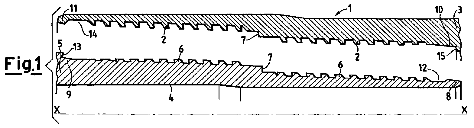
- Figures 1 and 2 represent a longitudinal half section of the pin and box elements of the joint shaped with three shoulders, along the X-X axis, in the non-coupled/coupled position;
- Figures 5 and 6 represent a longitudinal half-section of the pin and box elements of the joint shaped with two shoulders, along the X-X axis, in the non-coupled/coupled position;
- Figures 4 and 7 represent a complete section of the joint with the coupled pin and box elements. In particular, the drawings represent the longitudinal section of the joint with three details, 4 A, 4 B, 4 C and 7 A, 7 B, 7 C of the shoulders/metal seal. Figure 4 refers to the joint with three shoulders design (one external, one intermediate and one internal); figure 7 refers to the joint with only two shoulders (one external and one intermediate). Figure 3 represents a partial view, along the X-X axis, of the thread profile from which it can be seen that the preferred design includes both a negative loading angle and a positive inlet angle.
-
- With reference to the figures, (1) indicates the hollow terminal part of a box pipe (3) equipped with an internal thread (2), while (4) indicates the corresponding hollow terminal part of a pin pipe (5) equipped with an external thread (6).
- The pin and box elements of the pipe have a tapered-conical longitudinal section in which the conic zone varies from 8 to 16% depending on the diameter and thickness of the pipe.
- In correspondence with the half of the two threads (2) and (6), there is a shoulder (7), which is orthogonal to the axis of the pipes, as detailed in figures B. The ends of the present integral joint are shown in figures 4A/ 7 A and 4 C/7 C respectively.
- The pin element of the joint object of the present invention is shaped at the end with the external flares (8) and (9) which, by interfering with the internal insets (10) and (11) machined at the end of the box element, form two metal-to-metal seals, internal and external, which guarantee the complete sealing of the joint under any operating condition. Between the initial flare (8) of the pin element and the beginning of the thread (6), there is a slot (12) whose thickness is recovered at the end of the thread by the shoulder (13) orthogonal to the flare (9) . Between the initial inset (11) of the box element and the beginning of the thread (2), there is a slot (14) whose thickness is recovered at the end of the thread by the shoulder (15) substantially orthogonal to the inset (10) (see figure 4 C). In the alternative solution this shoulder is not present (see figure 7 C) but is absorbed by the inset (10).
- For purely illustrative purposes, the mechanical characteristics of the joint according to the present invention, as previously described in Fig.1, 2 and Fig.4, are provided hereunder, relating to pipes of 195.58 mm in diameter and 15.11 mm in thickness. The hight of the shoulders are about 2 mm, for the internal and external shoulders, and about 1.5 mm for the intermediate shoulder.
- The sum of the areas of the three shoulders is about 3500 mm2 with a cross-sectional area of the pipe body of about 8600 mm2 and a cross-sectional area of the joint of 6900 mm2. This gives a resulting joint tensile efficiency equal to about 80% of the pipe body yield strength (tensile efficiency % = 6900/8600 x 100 = 80%).
- Considering the area of the three shoulders, the compression efficiency is 50% of the tensile efficiency (compression efficiency % = 3500/6900 x 100 = 50%) . Also taking into account the contribution of the thread (which can be estimated at about 30%) the compression efficiency can be said to be equal to the tensile efficiency of the joint (about 80%).
Claims (1)
- An integral joint for the connection of two pipes comprising:a) a first box element with a tapered-conical longitudinal section, equipped with an internal two-step thread machined at an end of a first pipe;b) a second pin element, equipped with an external two-step thread, machined at an end of a second pipe, having a tapered-conical longitudinal section, suitable for making-up inside the box element;c) a shoulder, orthogonal to the axis of the pipe, positioned on the pin element, half-way along the thread;d) a shoulder, orthogonal to the axis of the pipe, positioned half-way along the thread of the box element and suitable for mating with the shoulder of the pin element when the connection is made-up;e) two insets machined at the beginning and at the end of the box element respectively, suitable for interfering with corresponding flares machined at the beginning and at the end of the pin element;
characterized in that:f) between the flare and beginning of the thread of the pin element there is an annular slot, the depth of which (allowing the thread to be machined) is recovered with a corresponding shoulder, having a thickness substantially equal to the depth of said slot, at the end of the thread;g) between the initial inset of the box element and beginning of the corresponding thread, there is another annular slot, similar to the first, the depth of which (allowing the thread to be machined) is recovered with a possible corresponding shoulder or is absorbed in the inset at the end of the thread.
Applications Claiming Priority (2)
| Application Number | Priority Date | Filing Date | Title |
|---|---|---|---|
| ITMI990336 | 1999-02-19 | ||
| IT1999MI000336A IT1309704B1 (en) | 1999-02-19 | 1999-02-19 | INTEGRAL JUNCTION OF TWO PIPES |
Publications (2)
| Publication Number | Publication Date |
|---|---|
| EP1030029A1 true EP1030029A1 (en) | 2000-08-23 |
| EP1030029B1 EP1030029B1 (en) | 2003-10-22 |
Family
ID=11381957
Family Applications (1)
| Application Number | Title | Priority Date | Filing Date |
|---|---|---|---|
| EP00200437A Expired - Lifetime EP1030029B1 (en) | 1999-02-19 | 2000-02-10 | Integral joint for the connection of two pipes |
Country Status (11)
| Country | Link |
|---|---|
| US (1) | US6347814B1 (en) |
| EP (1) | EP1030029B1 (en) |
| JP (1) | JP4498519B2 (en) |
| CN (1) | CN1201062C (en) |
| AR (1) | AR022617A1 (en) |
| AT (1) | ATE252680T1 (en) |
| BR (1) | BR0000555A (en) |
| CA (1) | CA2298901C (en) |
| DE (1) | DE60006013D1 (en) |
| IT (1) | IT1309704B1 (en) |
| RU (1) | RU2187735C2 (en) |
Cited By (9)
| Publication number | Priority date | Publication date | Assignee | Title |
|---|---|---|---|---|
| WO2006061577A1 (en) * | 2004-12-06 | 2006-06-15 | Hgds Inc | Improved pipe connection |
| WO2008110494A1 (en) * | 2007-03-14 | 2008-09-18 | Vallourec Mannesmann Oil & Gas France | Threaded tubular connection which is leak-proof under internal and external successive pressure loads |
| US7614667B2 (en) | 2004-12-06 | 2009-11-10 | Hgds Inc. | Pipe connection |
| CN1786542B (en) * | 2004-12-06 | 2010-08-11 | Hgds有限公司 | Improved pipe connection |
| US9200732B2 (en) | 2012-12-31 | 2015-12-01 | North American Specialty Products Llc | Flush joint pipe |
| EP3205918A4 (en) * | 2014-10-06 | 2018-05-30 | Nippon Steel & Sumitomo Metal Corporation | Threaded joint for steel pipe |
| GB2586308A (en) * | 2019-05-03 | 2021-02-17 | Oil States Ind Uk Ltd | Pipe coupling |
| EP3798409A1 (en) * | 2019-09-24 | 2021-03-31 | Vallourec Oil And Gas France | Threaded connection including an intermediate shoulder |
| EP3904745A4 (en) * | 2018-12-25 | 2022-02-16 | Nippon Steel Corporation | Steel-pipe threaded joint |
Families Citing this family (49)
| Publication number | Priority date | Publication date | Assignee | Title |
|---|---|---|---|---|
| FR2800150B1 (en) * | 1999-10-21 | 2001-12-07 | Vallourec Mannesmann Oil & Gas | EXTERNAL PRESSURE THREADED TUBULAR JOINT |
| IT1318179B1 (en) * | 2000-07-17 | 2003-07-23 | Dalmine Spa | INTEGRAL THREADED JOINT FOR PIPES. |
| US6749020B1 (en) * | 2000-11-07 | 2004-06-15 | Benoit Machine Inc. | Well screen two step coupled connector structure |
| US20070228729A1 (en) * | 2003-03-06 | 2007-10-04 | Grimmett Harold M | Tubular goods with threaded integral joint connections |
| FR2863031B1 (en) * | 2003-11-28 | 2006-10-06 | Vallourec Mannesmann Oil & Gas | REALIZATION, BY PLASTIC EXPANSION, OF AN ASSEMBLY OF TWO TUBULAR JOINTS THREADED SEALED WITH A SUB-THICKENER OF LOCAL AND INITIAL MATERIAL |
| FR2874988B1 (en) * | 2004-09-09 | 2008-05-02 | Vallourec Mannesmann Oil & Gas | MALE ELEMENT FOR A TUBULAR THREADED SEAL AFTER DIAMETER EXPANSION |
| EP2006589B1 (en) * | 2007-06-22 | 2011-08-31 | Tenaris Connections Aktiengesellschaft | Threaded joint with energizable seal |
| EP2017507B1 (en) * | 2007-07-16 | 2016-06-01 | Tenaris Connections Limited | Threaded joint with resilient seal ring |
| DE602007008890D1 (en) * | 2007-08-24 | 2010-10-14 | Tenaris Connections Ag | Method for increasing the fatigue resistance of a screw connection |
| FR2925946B1 (en) * | 2007-12-28 | 2009-12-11 | Vallourec Mannesmann Oil & Gas | TUBULAR THREADED SEAL AND RESISTANT TO SUCCESSIVE PRESSURE SOLICITATIONS |
| US8246086B2 (en) * | 2008-09-10 | 2012-08-21 | Beverly Watts Ramos | Low cost, high performance pipe connection |
| FR2940677B1 (en) * | 2008-12-29 | 2016-07-22 | Vallourec Mannesmann Oil & Gas France | SEALED TUBULAR JOINT USED IN THE PETROLEUM INDUSTRY |
| EP2243920A1 (en) | 2009-04-22 | 2010-10-27 | Tenaris Connections Aktiengesellschaft | Threaded joint for tubes, pipes and the like |
| EP2325435B2 (en) * | 2009-11-24 | 2020-09-30 | Tenaris Connections B.V. | Threaded joint sealed to [ultra high] internal and external pressures |
| US9222607B2 (en) * | 2009-12-04 | 2015-12-29 | Baker Hughes Incorporated | Threaded connection with metal to metal seal capable of expansion |
| EP2372208B1 (en) * | 2010-03-25 | 2013-05-29 | Tenaris Connections Limited | Threaded joint with elastomeric seal flange |
| EP2372211B1 (en) | 2010-03-26 | 2015-06-03 | Tenaris Connections Ltd. | Thin-walled pipe joint and method to couple a first pipe to a second pipe |
| US10215314B2 (en) * | 2010-08-23 | 2019-02-26 | Vallourec Oil And Gas France | Tubular threaded connection |
| US8882157B2 (en) * | 2010-09-27 | 2014-11-11 | United States Steel Corporation | Connecting oil country tubular goods |
| US9163296B2 (en) | 2011-01-25 | 2015-10-20 | Tenaris Coiled Tubes, Llc | Coiled tube with varying mechanical properties for superior performance and methods to produce the same by a continuous heat treatment |
| US9677346B2 (en) * | 2012-11-28 | 2017-06-13 | Ultra Premium Oilfield Services, Ltd. | Tubular connection with helically extending torque shoulder |
| US9970242B2 (en) | 2013-01-11 | 2018-05-15 | Tenaris Connections B.V. | Galling resistant drill pipe tool joint and corresponding drill pipe |
| US9803256B2 (en) | 2013-03-14 | 2017-10-31 | Tenaris Coiled Tubes, Llc | High performance material for coiled tubing applications and the method of producing the same |
| CN104060946A (en) * | 2013-03-21 | 2014-09-24 | 宝山钢铁股份有限公司 | Ultrahigh torsion-resistance metal airtight drill rod joint |
| EP2789700A1 (en) | 2013-04-08 | 2014-10-15 | DALMINE S.p.A. | Heavy wall quenched and tempered seamless steel pipes and related method for manufacturing said steel pipes |
| EP2789701A1 (en) | 2013-04-08 | 2014-10-15 | DALMINE S.p.A. | High strength medium wall quenched and tempered seamless steel pipes and related method for manufacturing said steel pipes |
| KR102197204B1 (en) | 2013-06-25 | 2021-01-04 | 테나리스 커넥션즈 비.브이. | High-chromium heat-resistant steel |
| FR3008763B1 (en) * | 2013-07-18 | 2015-07-31 | Vallourec Mannesmann Oil & Gas | ASSEMBLY FOR THE PRODUCTION OF A THREADED JOINT FOR DRILLING AND OPERATING HYDROCARBON WELLS AND RESULTING THREAD |
| US10428594B2 (en) * | 2013-11-22 | 2019-10-01 | Vetco Gray, LLC | Alignment guide feature for metal to metal seal protection on mechanical connections and couplings |
| US10293426B2 (en) * | 2014-01-07 | 2019-05-21 | Lincoln Global, Inc. | Increased durability welding torch assembly and components |
| CN104481422B (en) * | 2014-11-12 | 2016-10-26 | 中国石油天然气集团公司 | A kind of aluminium alloy drill pipe body and the attachment structure of steel joint |
| CN104533310B (en) * | 2014-12-05 | 2017-02-01 | 中国石油天然气集团公司 | Aluminum alloy drill rod pipe body and joint connecting structure |
| EP3128119A1 (en) * | 2015-08-05 | 2017-02-08 | Hydril Company | Threaded tubular connection |
| CN108700230B (en) * | 2016-02-23 | 2019-11-22 | 日本制铁株式会社 | Screw joint for steel pipe |
| US11124852B2 (en) | 2016-08-12 | 2021-09-21 | Tenaris Coiled Tubes, Llc | Method and system for manufacturing coiled tubing |
| FR3060701A1 (en) * | 2016-12-16 | 2018-06-22 | Vallourec Oil And Gas France | THREADED SEAL FOR TUBULAR COMPONENT |
| US10434554B2 (en) | 2017-01-17 | 2019-10-08 | Forum Us, Inc. | Method of manufacturing a coiled tubing string |
| UA123817C2 (en) | 2017-05-15 | 2021-06-02 | Ніппон Стіл Корпорейшн | Threaded coupling for steel piping |
| CN107558934A (en) * | 2017-10-09 | 2018-01-09 | 天津钢管集团股份有限公司 | Extreme line casing thread joint |
| CA2984826A1 (en) | 2017-11-07 | 2019-05-07 | Complete Group Technologies Ltd. | Multiple tapered threaded connection |
| MX2020002923A (en) * | 2017-11-09 | 2020-07-22 | Nippon Steel Corp | Threaded joint for steel pipes. |
| MX2020011162A (en) | 2018-04-25 | 2021-01-29 | Hydril Co | Wedge thread connection for tubular goods. |
| EP3572612B1 (en) * | 2018-05-25 | 2020-10-07 | Vallourec Oil And Gas France | Tubular threaded connection |
| EP3572613B1 (en) | 2018-05-25 | 2020-10-21 | Vallourec Oil And Gas France | Threaded tubular connection for casing |
| PL3572611T3 (en) | 2018-05-25 | 2021-07-05 | Vallourec Oil And Gas France | Tubular threaded connection |
| RU2762926C1 (en) * | 2018-08-24 | 2021-12-23 | Ниппон Стил Корпорейшн | Threaded connection for steel pipes |
| US20200208760A1 (en) * | 2018-12-27 | 2020-07-02 | Ultra Premium Services, L.L.C. | Connection having balanced pin and box face thickness |
| US10774959B1 (en) * | 2019-11-18 | 2020-09-15 | LFS Technologies, Inc. | Flush joint high torque thread |
| AU2020423748B2 (en) * | 2020-01-17 | 2023-09-07 | Nippon Steel Corporation | Threaded connection for pipe |
Citations (4)
| Publication number | Priority date | Publication date | Assignee | Title |
|---|---|---|---|---|
| EP0108980A2 (en) * | 1982-11-15 | 1984-05-23 | Quanex Corporation | Tubular connection |
| WO1993018329A1 (en) | 1992-03-09 | 1993-09-16 | Marubeni Tubulars, Inc. | Stabilized center-shoulder-sealed tubular connection |
| EP0767335A1 (en) * | 1995-10-03 | 1997-04-09 | Vallourec Oil & Gas | Threaded joint for tubes |
| EP0803637A2 (en) * | 1996-04-26 | 1997-10-29 | Oil States Industries (UK) Ltd. | Pipe connector device with pin and box members having corresponding frusto-conical surfaces |
Family Cites Families (4)
| Publication number | Priority date | Publication date | Assignee | Title |
|---|---|---|---|---|
| US4610467A (en) * | 1981-07-06 | 1986-09-09 | Dril-Quip, Inc. | Connector |
| US5066052A (en) * | 1989-03-08 | 1991-11-19 | Baroid Technology, Inc. | Threaded pipe joint having improved seal ring entrapment |
| US5505502A (en) * | 1993-06-09 | 1996-04-09 | Shell Oil Company | Multiple-seal underwater pipe-riser connector |
| FR2761450B1 (en) * | 1997-03-27 | 1999-05-07 | Vallourec Mannesmann Oil & Gas | THREADED JOINT FOR TUBES |
-
1999
- 1999-02-19 IT IT1999MI000336A patent/IT1309704B1/en active
-
2000
- 2000-02-09 RU RU2000103498/06A patent/RU2187735C2/en active
- 2000-02-10 AT AT00200437T patent/ATE252680T1/en not_active IP Right Cessation
- 2000-02-10 EP EP00200437A patent/EP1030029B1/en not_active Expired - Lifetime
- 2000-02-10 DE DE60006013T patent/DE60006013D1/en not_active Expired - Lifetime
- 2000-02-15 CA CA002298901A patent/CA2298901C/en not_active Expired - Fee Related
- 2000-02-16 BR BR0000555-0A patent/BR0000555A/en not_active IP Right Cessation
- 2000-02-17 US US09/505,684 patent/US6347814B1/en not_active Expired - Lifetime
- 2000-02-17 AR ARP000100669A patent/AR022617A1/en active IP Right Grant
- 2000-02-18 JP JP2000041154A patent/JP4498519B2/en not_active Expired - Fee Related
- 2000-02-18 CN CNB00102261XA patent/CN1201062C/en not_active Expired - Fee Related
Patent Citations (4)
| Publication number | Priority date | Publication date | Assignee | Title |
|---|---|---|---|---|
| EP0108980A2 (en) * | 1982-11-15 | 1984-05-23 | Quanex Corporation | Tubular connection |
| WO1993018329A1 (en) | 1992-03-09 | 1993-09-16 | Marubeni Tubulars, Inc. | Stabilized center-shoulder-sealed tubular connection |
| EP0767335A1 (en) * | 1995-10-03 | 1997-04-09 | Vallourec Oil & Gas | Threaded joint for tubes |
| EP0803637A2 (en) * | 1996-04-26 | 1997-10-29 | Oil States Industries (UK) Ltd. | Pipe connector device with pin and box members having corresponding frusto-conical surfaces |
Cited By (14)
| Publication number | Priority date | Publication date | Assignee | Title |
|---|---|---|---|---|
| US7614667B2 (en) | 2004-12-06 | 2009-11-10 | Hgds Inc. | Pipe connection |
| WO2006061577A1 (en) * | 2004-12-06 | 2006-06-15 | Hgds Inc | Improved pipe connection |
| CN1786542B (en) * | 2004-12-06 | 2010-08-11 | Hgds有限公司 | Improved pipe connection |
| US8641100B2 (en) | 2007-03-14 | 2014-02-04 | Vallourec Mannesmann Oil & Gas France | Threaded tubular connection which is leak-proof under internal and external successive pressure loads |
| FR2913746A1 (en) * | 2007-03-14 | 2008-09-19 | Vallourec Mannesmann Oil Gas F | SEALED TUBULAR THREAD SEAL FOR INTERNAL AND EXTERNAL PRESSURE SOLUTIONS |
| CN101631981B (en) * | 2007-03-14 | 2011-06-22 | 法国瓦罗里克·曼尼斯曼油汽公司 | Threaded tubular connection which is leak-proof under internal and external successive pressure loads |
| WO2008110494A1 (en) * | 2007-03-14 | 2008-09-18 | Vallourec Mannesmann Oil & Gas France | Threaded tubular connection which is leak-proof under internal and external successive pressure loads |
| US9200732B2 (en) | 2012-12-31 | 2015-12-01 | North American Specialty Products Llc | Flush joint pipe |
| US9568120B2 (en) | 2012-12-31 | 2017-02-14 | North American Specialty Products Llc | Flush joint pipe |
| EP3205918A4 (en) * | 2014-10-06 | 2018-05-30 | Nippon Steel & Sumitomo Metal Corporation | Threaded joint for steel pipe |
| US10400922B2 (en) | 2014-10-06 | 2019-09-03 | Nippon Steel Corporation | Threaded joint for steel pipes |
| EP3904745A4 (en) * | 2018-12-25 | 2022-02-16 | Nippon Steel Corporation | Steel-pipe threaded joint |
| GB2586308A (en) * | 2019-05-03 | 2021-02-17 | Oil States Ind Uk Ltd | Pipe coupling |
| EP3798409A1 (en) * | 2019-09-24 | 2021-03-31 | Vallourec Oil And Gas France | Threaded connection including an intermediate shoulder |
Also Published As
| Publication number | Publication date |
|---|---|
| DE60006013D1 (en) | 2003-11-27 |
| BR0000555A (en) | 2000-10-17 |
| US6347814B1 (en) | 2002-02-19 |
| JP2000240862A (en) | 2000-09-08 |
| CA2298901C (en) | 2008-04-22 |
| CN1265445A (en) | 2000-09-06 |
| JP4498519B2 (en) | 2010-07-07 |
| RU2187735C2 (en) | 2002-08-20 |
| EP1030029B1 (en) | 2003-10-22 |
| CA2298901A1 (en) | 2000-08-19 |
| ITMI990336A1 (en) | 2000-08-19 |
| AR022617A1 (en) | 2002-09-04 |
| ATE252680T1 (en) | 2003-11-15 |
| IT1309704B1 (en) | 2002-01-30 |
| CN1201062C (en) | 2005-05-11 |
Similar Documents
| Publication | Publication Date | Title |
|---|---|---|
| EP1030029B1 (en) | Integral joint for the connection of two pipes | |
| CA2185251C (en) | Threaded joint for tubes | |
| EP0897504B1 (en) | Threaded tool joint with dual mating shoulders | |
| EP1570200B1 (en) | Method for producing a threaded tubular connection sealed to the outside | |
| CN112567107B (en) | Tubular threaded connection | |
| BR112015006015B1 (en) | THREADED TUBULAR CONNECTION | |
| EP3803028B1 (en) | Tubular threaded connection | |
| US9470344B2 (en) | Component for drilling and operating hydrocarbon wells | |
| CN114402116A (en) | Threaded connection for an oil well casing string | |
| WO2002035128A2 (en) | Threaded pipe joint | |
| US11905766B2 (en) | Threaded tubular connection for casing | |
| GB2472861A (en) | A threaded pipe connector of reduced bending stiffness | |
| MXPA00001674A (en) | Integral joint for the connection of two pipes | |
| OA19854A (en) | Tubular threaded connection. | |
| OA19855A (en) | Threaded tubular connection for casing. |
Legal Events
| Date | Code | Title | Description |
|---|---|---|---|
| PUAI | Public reference made under article 153(3) epc to a published international application that has entered the european phase |
Free format text: ORIGINAL CODE: 0009012 |
|
| AK | Designated contracting states |
Kind code of ref document: A1 Designated state(s): AT BE CH CY DE DK ES FI FR GB GR IE IT LI LU MC NL PT SE |
|
| AX | Request for extension of the european patent |
Free format text: AL;LT;LV;MK;RO;SI |
|
| 17P | Request for examination filed |
Effective date: 20010116 |
|
| AKX | Designation fees paid |
Free format text: AT BE CH CY DE DK ES FI FR GB GR IE IT LI LU MC NL PT SE |
|
| GRAH | Despatch of communication of intention to grant a patent |
Free format text: ORIGINAL CODE: EPIDOS IGRA |
|
| GRAH | Despatch of communication of intention to grant a patent |
Free format text: ORIGINAL CODE: EPIDOS IGRA |
|
| GRAS | Grant fee paid |
Free format text: ORIGINAL CODE: EPIDOSNIGR3 |
|
| GRAA | (expected) grant |
Free format text: ORIGINAL CODE: 0009210 |
|
| AK | Designated contracting states |
Kind code of ref document: B1 Designated state(s): AT BE CH CY DE DK ES FI FR GB GR IE IT LI LU MC NL PT SE |
|
| PG25 | Lapsed in a contracting state [announced via postgrant information from national office to epo] |
Ref country code: CH Free format text: LAPSE BECAUSE OF FAILURE TO SUBMIT A TRANSLATION OF THE DESCRIPTION OR TO PAY THE FEE WITHIN THE PRESCRIBED TIME-LIMIT Effective date: 20031022 Ref country code: IT Free format text: LAPSE BECAUSE OF FAILURE TO SUBMIT A TRANSLATION OF THE DESCRIPTION OR TO PAY THE FEE WITHIN THE PRESCRIBED TIME-LIMIT;WARNING: LAPSES OF ITALIAN PATENTS WITH EFFECTIVE DATE BEFORE 2007 MAY HAVE OCCURRED AT ANY TIME BEFORE 2007. THE CORRECT EFFECTIVE DATE MAY BE DIFFERENT FROM THE ONE RECORDED. Effective date: 20031022 Ref country code: CY Free format text: LAPSE BECAUSE OF FAILURE TO SUBMIT A TRANSLATION OF THE DESCRIPTION OR TO PAY THE FEE WITHIN THE PRESCRIBED TIME-LIMIT Effective date: 20031022 Ref country code: FR Free format text: LAPSE BECAUSE OF FAILURE TO SUBMIT A TRANSLATION OF THE DESCRIPTION OR TO PAY THE FEE WITHIN THE PRESCRIBED TIME-LIMIT Effective date: 20031022 Ref country code: NL Free format text: LAPSE BECAUSE OF FAILURE TO SUBMIT A TRANSLATION OF THE DESCRIPTION OR TO PAY THE FEE WITHIN THE PRESCRIBED TIME-LIMIT Effective date: 20031022 Ref country code: BE Free format text: LAPSE BECAUSE OF FAILURE TO SUBMIT A TRANSLATION OF THE DESCRIPTION OR TO PAY THE FEE WITHIN THE PRESCRIBED TIME-LIMIT Effective date: 20031022 Ref country code: LI Free format text: LAPSE BECAUSE OF FAILURE TO SUBMIT A TRANSLATION OF THE DESCRIPTION OR TO PAY THE FEE WITHIN THE PRESCRIBED TIME-LIMIT Effective date: 20031022 Ref country code: AT Free format text: LAPSE BECAUSE OF FAILURE TO SUBMIT A TRANSLATION OF THE DESCRIPTION OR TO PAY THE FEE WITHIN THE PRESCRIBED TIME-LIMIT Effective date: 20031022 Ref country code: FI Free format text: LAPSE BECAUSE OF FAILURE TO SUBMIT A TRANSLATION OF THE DESCRIPTION OR TO PAY THE FEE WITHIN THE PRESCRIBED TIME-LIMIT Effective date: 20031022 |
|
| REG | Reference to a national code |
Ref country code: GB Ref legal event code: FG4D |
|
| REG | Reference to a national code |
Ref country code: CH Ref legal event code: EP |
|
| REG | Reference to a national code |
Ref country code: IE Ref legal event code: FG4D |
|
| REF | Corresponds to: |
Ref document number: 60006013 Country of ref document: DE Date of ref document: 20031127 Kind code of ref document: P |
|
| PG25 | Lapsed in a contracting state [announced via postgrant information from national office to epo] |
Ref country code: GR Free format text: LAPSE BECAUSE OF FAILURE TO SUBMIT A TRANSLATION OF THE DESCRIPTION OR TO PAY THE FEE WITHIN THE PRESCRIBED TIME-LIMIT Effective date: 20040122 Ref country code: SE Free format text: LAPSE BECAUSE OF FAILURE TO SUBMIT A TRANSLATION OF THE DESCRIPTION OR TO PAY THE FEE WITHIN THE PRESCRIBED TIME-LIMIT Effective date: 20040122 Ref country code: DK Free format text: LAPSE BECAUSE OF FAILURE TO SUBMIT A TRANSLATION OF THE DESCRIPTION OR TO PAY THE FEE WITHIN THE PRESCRIBED TIME-LIMIT Effective date: 20040122 |
|
| PG25 | Lapsed in a contracting state [announced via postgrant information from national office to epo] |
Ref country code: DE Free format text: LAPSE BECAUSE OF FAILURE TO SUBMIT A TRANSLATION OF THE DESCRIPTION OR TO PAY THE FEE WITHIN THE PRESCRIBED TIME-LIMIT Effective date: 20040123 |
|
| PG25 | Lapsed in a contracting state [announced via postgrant information from national office to epo] |
Ref country code: ES Free format text: LAPSE BECAUSE OF FAILURE TO SUBMIT A TRANSLATION OF THE DESCRIPTION OR TO PAY THE FEE WITHIN THE PRESCRIBED TIME-LIMIT Effective date: 20040202 |
|
| PG25 | Lapsed in a contracting state [announced via postgrant information from national office to epo] |
Ref country code: LU Free format text: LAPSE BECAUSE OF NON-PAYMENT OF DUE FEES Effective date: 20040210 Ref country code: IE Free format text: LAPSE BECAUSE OF NON-PAYMENT OF DUE FEES Effective date: 20040210 |
|
| PG25 | Lapsed in a contracting state [announced via postgrant information from national office to epo] |
Ref country code: MC Free format text: LAPSE BECAUSE OF NON-PAYMENT OF DUE FEES Effective date: 20040228 |
|
| NLV1 | Nl: lapsed or annulled due to failure to fulfill the requirements of art. 29p and 29m of the patents act | ||
| REG | Reference to a national code |
Ref country code: CH Ref legal event code: PL |
|
| PLBE | No opposition filed within time limit |
Free format text: ORIGINAL CODE: 0009261 |
|
| STAA | Information on the status of an ep patent application or granted ep patent |
Free format text: STATUS: NO OPPOSITION FILED WITHIN TIME LIMIT |
|
| 26N | No opposition filed |
Effective date: 20040723 |
|
| EN | Fr: translation not filed | ||
| REG | Reference to a national code |
Ref country code: IE Ref legal event code: MM4A |
|
| PG25 | Lapsed in a contracting state [announced via postgrant information from national office to epo] |
Ref country code: PT Free format text: LAPSE BECAUSE OF NON-PAYMENT OF DUE FEES Effective date: 20040322 |
|
| PGFP | Annual fee paid to national office [announced via postgrant information from national office to epo] |
Ref country code: GB Payment date: 20140227 Year of fee payment: 15 |
|
| GBPC | Gb: european patent ceased through non-payment of renewal fee |
Effective date: 20150210 |
|
| PG25 | Lapsed in a contracting state [announced via postgrant information from national office to epo] |
Ref country code: GB Free format text: LAPSE BECAUSE OF NON-PAYMENT OF DUE FEES Effective date: 20150210 |