EP1029840B1 - Process for separating HFC-32 and HFC-125 - Google Patents
Process for separating HFC-32 and HFC-125 Download PDFInfo
- Publication number
- EP1029840B1 EP1029840B1 EP00112323A EP00112323A EP1029840B1 EP 1029840 B1 EP1029840 B1 EP 1029840B1 EP 00112323 A EP00112323 A EP 00112323A EP 00112323 A EP00112323 A EP 00112323A EP 1029840 B1 EP1029840 B1 EP 1029840B1
- Authority
- EP
- European Patent Office
- Prior art keywords
- hfc
- column
- azeotrope
- mixture
- composition
- Prior art date
- Legal status (The legal status is an assumption and is not a legal conclusion. Google has not performed a legal analysis and makes no representation as to the accuracy of the status listed.)
- Expired - Lifetime
Links
Images
Classifications
-
- C—CHEMISTRY; METALLURGY
- C07—ORGANIC CHEMISTRY
- C07C—ACYCLIC OR CARBOCYCLIC COMPOUNDS
- C07C17/00—Preparation of halogenated hydrocarbons
- C07C17/38—Separation; Purification; Stabilisation; Use of additives
- C07C17/383—Separation; Purification; Stabilisation; Use of additives by distillation
- C07C17/386—Separation; Purification; Stabilisation; Use of additives by distillation with auxiliary compounds
Definitions
- the instant invention relates to a process for separating HFC-32 and HFC-125 from a first mixture by using an extractant comprising methylene chloride, the process comprising the steps of: adding the extractant to the first mixture in order to form a second mixture, separating HFC-32 and HFC-125 in the second mixture by extractively distilling the second mixture in an extractive distillation zone of a distillation column and thereby recovering HFC-125 as an overhead product of the column and HFC-32 as a bottom product from the column.
- Pentafluoroethane (CHF2-CF3 or HFC-125) is a useful non-chlorine containing fluorocarbon that is especially desirable for use as a refrigerant, blowing agent, propellant, fire extinguishing agent, sterilant carrier gas, among other uses.
- Difluoromethane (CH2F2 or HFC-32) is another desirable non-chlorine containing fluorocarbon that is also valuable as a refrigerant among other uses.
- HFC-32 can be formed, for example, by the catalytic fluorination of dichloromethane (HCC-30 or methylene chloride) with HF.
- HFC-32 is known to form an azeotropic or azeotrope-like composition with HFC-125.
- the instant invention solves problems associated with conventional processes by providing a process wherein methylene chloride is used as an extractant in an extractive distillation process for separating HFC-32 and HFC-125, with HFC-32 exiting the extractive distillation column bottoms with the methylene chloride and HFC-125 exiting the extractive distillation column overhead.
- the present invention relates to a process for separating HFC-32 and HFC-125 from a first mixture by using an extractant comprising methylene chloride.
- the process comprises the steps of adding the extractant to the first mixture in order to form a second mixture, separating HFC-32 and HFC-125 in the second mixture by extractively distilling the second mixture in an extractive distillation zone of a distillation column and thereby recovering HFC-125 as an overhead product of the column while recovering HFC-32 from the column bottom.
- HFC-32 and HFC-125 can be co-produced by contacting a mixture comprising a HFC-32 precursor such as methylene chloride (HCC-30 or CH2Cl2) and a HFC-125 precursor such as HCFC-123 (dichlorotrifluoroethane) and/or HCFC-124 (chlorotetrafluoroethane) with HF in the presence of a catalyst, e.g., CrCl3 on a carbon support or Cr2O3.
- a catalyst e.g., CrCl3 on a carbon support or Cr2O3.
- the reaction product contains predominant quantities of HFC-32 and HFC-125 along with one or more of the following.
- HCFC-31 chlorofluoromethane
- HCC-30 diichloromethane or methylene chloride
- CFC-114a diichlorotetrafluoroethane
- CFC-115 chloropentafluoroethane
- HCFC-124 chlorotetrafluoroethane
- HCFC-133a chlorotrifluoroethane
- HF hydrogen fluoride
- HCl hydrochloride
- Impurities other than CFC-115 and hydrogen fluoride can be efficiently removed from the resulting HFC-125 containing products by conventional distillation or other processes known by one skilled in the art.
- the CFC-115 and/or the hydrogen fluoride can be removed from the HFC-125 containing products by employing the process of the parent application EP 0 840 719 A1.
- methylene chloride is employed as an extractant in an extractive distillation for separating HFC-32 and HFC-125. This process permits HFC-125 to exit overhead from the distillation column, while allowing methylene chloride and HFC-32 to exit the column bottoms.
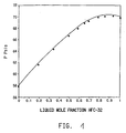
- FIGURE 1 is a graphical representation at about -153 C of an azeotropic and azeotrope-like composition formed between HFC-32 and HFC-125.
- HFC-125 and HFC-32 which are the primary constituents of a first mixture, in their separated and pure state have boiling points, respectively, of about -48.5 and -51,7° degrees C.
- the relative volatility at atmospheric pressure of HFC-125/HFC-32 was found to be 1.0 as 90% purity of HFC-32 was approached (US 4 978 467; Table 1, col. 5).
- PTx Method To determine the relative volatility of HFC-125 and HFC-32 the so-called PTx Method was used. In this procedure, the total absolute pressure in a cell of known volume is measured at a constant temperature for various known binary compositions. Use of the PTx Method is described in greater detail in "Phase Equilibrium in Process Design", Wiley-Interscience Publisher, 1970, written by Harold R. Null, on pages 124 to 126; the entire disclosure of which is hereby incorporated by reference.
- NRTL Non-Random, Two-Liquid
- azeotrope or "azeotropic” composition is meant a constant-boiling liquid admixture of two or more substances that behaves as a single substance.
- azeotrope or azeotropic composition or mixture One way to characterize an azeotrope or azeotropic composition or mixture is that the vapor produced by partial evaporation or distillation of the liquid has the same composition as the liquid from which it was evaporated or distilled, e.g., the admixture distills/refluxes without compositional change.
- Constant boiling compositions are characterized as azeotropic because they exhibit either a maximum or minimum boiling point, as compared with that of the non-azeotropic mixture of the same components.
- An azeotropic composition can also be characterized as the maximum or minimum vapor pressure for a mixture at a given temperature when plotted as a function of mole fraction.
- azeotrope-like composition is meant a constant boiling, or substantially constant boiling admixture of two or more substances that behaves as a single substance.
- One way to characterize an azeotrope-like composition is that the vapor produced by partial evaporation or distillation of the liquid has substantially the same composition as the liquid from which it was evaporated or distilled, e.g., the admixture distills/refluxes without substantial compositional change.
- An azeotrope-like composition can also be characterized by the area, which is shown by plotting vapor pressure at a given temperature as a function of mole fraction, that is adjacent to the maximum or minimum vapor pressure.
- a composition is azeotrope-like, if, after 50 weight percent of the composition is removed such as by evaporation or boiling off, the change between the original composition and the composition remaining is less than about 6 %, and normally less than about 3 % relative to the original composition.
- effective amount is intended to refer to the amount of each component of the inventive compositions which, when combined, results in the formation of an azeotropic or azeotrope-like composition.
- This definition includes the amount of each component, which amounts may vary depending on the pressure applied to the composition so long as the azeotropic or azeotropic-like compositions continue to exist at the different pressures, but with possible different boiling points.
- Effective amount also includes the amounts, such as may be expressed in weight percentages, of each component of the compositions of the instant invention which form azeotropic or azeotrope-like compositions at temperatures or pressures other than as described herein.
- Azeotropic or azeotrope-like compositions consist essentially of effective amounts of HFC-32 and HFC-125 such that after about 50 weight percent of an original composition is evaporated or boiled off to produce a remaining composition, the change between the original composition and the remaining composition is typically no more than about 6% and normally no more than about 3% or less relative to the original composition.
- the azeotrope or azeotrope-like compositions of the present invention may be formed by operating a conventional distillation apparatus, when practicing the inventive extractive distillation apparatus, and by combining effective amounts of the components by any convenient method including mixing, combining, among others. For best results, a preferred method is to weigh the desired component amounts, and thereafter combine them in an appropriate container.
- the HFC-125/HFC-32 azeotrope can also be formed under a variety of temperatures and pressures. At a temperature of about -15.3 °C, an azeotrope can form consisting essentially of about 9.1 mole % HFC-125 and about 90.9 mole % HFC-32 having a pressure of about 484,7 kPa (70.3 psia).
- Figure 1 illustrates graphically the results of measurements made at -15.3 °C showing formation of an azeotropic or azeotrope-like composition consisting essentially of HFC-32 and HFC-125, as indicated by mixture of about 90.9 moles % HFC-32 and about 9.1 mole % HFC-125 having a higher vapor pressure than either pure component or other HFC-32/HFC-125 mixtures at this temperature, with the composition of the vapor space in the maximum pressure region being that of the azeotrope at the specific temperature and pressure.
- an azeotrope forms consisting essentially of about 96.0 mole % HFC-32 and 4.0 mole % HFC-125 having a pressure of about 2799.3 kPa (406 psia). Based upon these results and the previously described NRTL references, we determined that an azeotrope can form at a temperature of about -50 °C consisting essentially of about 84.9 mole % HFC-32 and about 15.1 mole % HFC-125 having a pressure of about 111.7 kPa (16.2 psia).
- HFC-125 and HFC-32 are co-produced in accordance with the instant invention or obtained from any other suitable source are difficult to separate due to the formation of an HFC-125/HFC-32 azeotrope.
- methylene chloride can be employed as an extractant in an extractive distillation-process that allows for efficient separation of the HFC-125 from the HFC-32.
- the HFC-32 may subsequently be separated from the methylene chloride by any number of known techniques, including simple distillation.
- the specific conditions which can be used for practicing the invention also depend upon a number of parameters such as the diameter of the column, feed points, number of separation stages in the column, among others.
- the operating pressure of the extractive distillation system may range from about 103.4 to 2413.2 kPa (15 to 350 psia), normally about 344.8 to 2068.4 kPa (50 to 300 psia).
- an increase in the methylene chloride feed rate relative to the HFC-125/HFC-32 feed rate causes an increase in the purity of the separated HFC-125 relative to the HFC-32.
- increasing the reflux results in an decreased methylene chloride in the overhead distillate.
- the temperature of the condenser which is located adjacent to the top of the column, is normally sufficient to substantially condense the HFC-125.
- ppm and ppmw are the parts-per-million-by-weight concentration of a compound in the identified stream.
- kilograms-per-hour flowrate of the designated compound or stream In the following examples and comparative examples, “kph” and “kg/hr” are the kilograms-per-hour flowrate of the designated compound or stream. In parentheses following the kilograms-per-hour values are the equivalent values in the units of "pph” or "lbs/hour", the pounds-per-hour flowrate of the designated compound or stream.
- a fresh feed stream consisting of HFC-32 and HFC-125 is fed to a first distillation column operated to separate the HFC-32 from the HFC-125.
- the column has 92 stages assumed to operate at 100% efficiency, with the condenser designated as stage 1.
- the column is 152,4 cm (60 inches) in diameter.
- the fresh feed stream contains equal weights of HFC-32 and HFC-125 and is fed onto stage 40 at -10 °C.
- the distillate from a second column that is fed back to this first column as a recycle feed stream also contains HFC-32 and HFC-125, and is also fed onto stage 40 of the first column.
- the condenser is operating at 24.1 °C.
- the reboiler is operating at 32.5 °C
- the column is operating at 1551,3 kPa (225 psig) pressure.
- the distillate from the first column is then fed as the feed to a second column.
- This second column has 92 stages assumed to operate at 100% efficiency, with the condenser designated at stage 1.
- This second column is 221 cm (87 inches) in diameter.
- the feed stream is fed onto stage 40.
- the condenser is operating at -46.0 °C
- the reboiler is operating at -43.7 °C
- the column is operating at 34,5 kPa (5 psig).
- This Comparative Example shows that even with extremely large columns with many stages and an extremely high rate of reflux, a high efficiency of separation of the HFC-32 and HFC-125 cannot be obtained in a single column.
- the separation efficiency in a single column is limited by the existence of the HFC-125/HFC-32 azeotrope.
- a feed stream consisting of approximately equal weights of HFC-32 and HFC-125 are fed to a first distillation column having 62 stages assumed to operate at 100 % efficiency, with the condenser designated as stage 1.
- the column is 48.26 cm (19 inches) in diameter.
- the column is operated at 413.7 kPa (60 psig), with the condenser operating at -8.1 degrees C, and the reboiler operating at 50.1 degrees C.
- the feed enters the column at -10 degrees C and is fed into the column onto stage 38.
- Methylene chloride from the bottoms ofa second column is fed into the first column as an extractant onto stage 12 at -5 degrees C.
- the bottoms stream from the first column is then fed to the second distillation column, which has 24 stages assumed to operate at 100 % efficiency, with the condenser designated as stage 1.
- stage 1 The second column is 23 inches in diameter.
- the column is operated at 482.7 kPa (70 psig), with the condenser operating at -9.9 °C, and the reboiler operating at 100 °C.
- the feed is fed into the column onto stage 12.
- the reflux flow in this example is 906 Kg/h (2000 pph).
- Temp is the temperature the reaction is being run, in degrees C.
- HF/Tot.Org is the HF / Total Organic molar feed ratio to the reactor.
- HF/HCC-30 is the HF / HCC-30 molar feed ratio to the reactor.
- HF/HCFC-124" is the HF / HCFC-124 molar feed ratio to the reactor.
- %32 is the organic mole % HFC-32 in the reactor off-gas.
- %125 is the organic mole % HFC-125 in the reactor off-gas.
- %115 is the organic mole % CFC-115 in the reactor off-gas.
- This Example shows how a variety of HFC-32 and HFC-125 molar ratios and productivities may be obtained by adjusting feed ratios and operating conditions.
- %HCC-30 %HFC-32 %HFC-125 26 327 5.2 58 40 27 12 304 3.4 64 38 20 12 302 3.4 42 24 24 12 302 7.2 66 47 18 12 302 7.2 44 31 32 26 302 5.2 58 32 18 27 329 5.2 58 40 27 26 327 5.3 69 49 24 26 327 4.9 51 36 35
- Contact Time is the contact time in the reactor, in seconds.
- Tempo is the temperature the reaction is being run, in degrees C.
- HF/Tot.Org.” is the HF / Total Organic molar feed ratio to the reactor.
- % HCC-30 is the organic mole % HCC-30 in the feed stream to the reactor.
- % HFC-32 is the organic mole % HFC-32 in the reactor off-gas.
- % HFC-125" is the organic mole % HFC-125 in the reactor off-gas.
- This Example shows how a variety of HFC-32 and HFC-125 molar ratios and productivities may be obtained by adjusting feed ratios and operating conditions.
- this chemistry as shown in Example 2 and Example 3 may be operated at temperatures that range from about 175 to 400 °C; normally from about 250 to 350 °C.
- This chemistry may also be operated by employing an HF/total organic molar feed ratio of from about 2/1 to 10/1; normally from about 4/1 to 8/1, and may be operated from atmospheric pressure up to 1379.1 kPa (200 psig).
- the chemistry may be used to obtain off-gas compositions containing from about 5 to 70 organic mole % HFC-125 and from 5 to 70 organic mole % HFC-32.
- the catalyst of Example 3 is desirable for this chemistry because the catalyst of Example 3 is particularly resistant to deactivation in this chemistry, and the catalyst of Example 3 can subsequently be regenerated after any activity loss.
- the catalyst of Example 3 may bereactivated, regaining its initial, or, in some cases, obtaining greater than its initial activity, by, for example, using the procedure described in US Patent No. 4,155,881.
Description
- The composition can be defined as an azeotrope of HFC-125 ("C") and HFC-32 ("D"), because the term "azeotrope" is at once both definitive and limitative, and requires effective amounts of C,D for this unique composition of matter which can be a constant boiling composition.
- It is well known by those skilled in the art, that, at different pressures, the composition of a given azeotrope will vary at least to some degree, and changes in pressure will also change, at least to some degree, the boiling point temperature. Thus, an azeotrope of HFC-125 ("C") and HFC-32 ("D") represents a unique type of relationship but with a variable composition which depends on temperature and/or pressure. Therefore, compositional ranges, rather than fixed compositions, are often used to define azeotropes.
- The composition can be defined as a particular weight percent relationship or mole percent relationship of HFC-125 ("C") and HFC-32 ("D"), which recognizing that such specific values point out only one particular relationship and that, in actuality, a series of such relationships, represented by C,D actually exist for a given azeotrope, varied by the influence of pressure.
- An azeotrope of HFC-125 ("C") and HFC-32 ("D"), can be characterized by defining the compositions as an azeotrope characterized by a boiling point at a given pressure, thus given identifying characteristics without unduly limiting the scope of the invention by a specific numerical composition, which is limited by and is only as accurate as the analytical equipment available.
| First Column Flow in Kgs Per Hour (Lbs per Hour) | |||||
| Column Fresh Feed | Recycle Feed | Column Reflux | Column Distillate | Column Bottoms | |
| HFC-125 | 938.94 (2070.00) | 732.34 (1614.53) | 8443.62 (18615.00) | 733.28 (1616.61) | 937.99 (2067.92) |
| HFC-32 | 938.94 (2070.00) | 1873.42 (4130.18) | (71380.00) | 2811.95 (6199.28) | 0.41 (0.90) |
| Second Column Flow in Kgs Per Hour (Lbs per Hour) | |||||
| Column Feed | Column Recycle | Column Distillate | Column Bottoms | ||
| HFC-125 | 733.28 (1616.61) | 11474.07 (25296.00) | 732.34 (1614.53) | 0.94 (2.08) | |
| HFC-32 | 2811.95 (6199.28) | 29349.24 (64704.00) | 1873.42 (4130.18) | 938.53 (2069.10) |
| First Column Flow in Kgs Per Hour (Lbs per Hour) | |||||
| Column Feeds | Column Reflux | Column Distillate | Column Bottoms | ||
| Stage 38 | Stage 12 | ||||
| HFC-125 | 938.94 (2070.00) | 0 | 1813.33 (3997.70) | 938.48 (2069) | 0.45 (1.00) |
| HFC-32 | 938.94 (2070.00) | 0 | 0.17 (0.37) | 0.086 (0.19) | 938.85 (2069.81) |
| CH2Cl2 | 0 | 18143.69 (400000.00) | <0.004 (<0.01) | <0.004 (<0.01) | 18143.69 (40000.00) |
| Second Column Flow in Kgs Per Hour (Lbs per Hour) | |||||
| Column Feed | Column Recycle | Column Distillate | Column Bottoms | ||
| HFC-125 | 0.45 (1.00) | 0.45 (1.00) | 0.45 (1.00) | <0.004 (<0.01) | |
| HFC-32 | 938.85 (2069.81) | 906.65 (1998.83) | 938.85 (2069.81) | <0.004 (<0.01) | |
| CH2Cl2 | 18143.69 (400000.00) | <0.004 (<0.01) | <0.004 (<0.01) | 18143.69 (400000.00) |
| Organic Mole % HFC-32, HFC-125, CFC-115 vs. Operating Condition | |||||||
| Contact Time (Sec) | HF/Tot.Org. in Feed (Mole Ratio) | HF/HCC-30 in Feed (Mole Ratio) | HF/HCFC-124 in Feed (Mole Ratio) | Temp (deg.C) | Mole %32 | Mole %125 | Mole %115 |
| 10 | 3.1 | 4.8 | 8.5 | 301 | 32.1 | 12.4 | <0.05 |
| 10 | 3.1 | 7.2 | 5.4 | 301 | 25.1 | 21.2 | 0.1 |
| 31 | 3.4 | 4.9 | 11.0 | 301 | 32.1 | 15.8 | 0.2 |
| 31 | 3.4 | 7.3 | 6.4 | 301 | 29.8 | 13.4 | 0.1 |
| 10 | 6.5 | 9.9 | 18.6 | 301 | 43.8 | 13.9 | <0.05 |
| 10 | 6.4 | 14.3 | 11.5 | 301 | 31.7 | 21.6 | <0.05 |
| 30 | 6.5 | 8.3 | 30.3 | 301 | 48.9 | 17.6 | 0.1 |
| 31 | 8.0 | 16.6 | 15.5 | 301 | 39.3 | 27.5 | 0.2 |
| 20 | 4.7 | 7.9 | 11.8 | 301 | 36.0 | 21.5 | 0.1 |
| 20 | 5.0 | 8.6 | 11.8 | 327 | 42.8 | 17.4 | 0.2 |
| 20 | 4.7 | 7.9 | 11.8 | 327 | 30.0 | 37.4 | 0.3 |
| 20 | 4.8 | 6.8 | 15.7 | 327 | 34.8 | 33.4 | 0.3 |
| 20 | 5.3 | 11.9 | 9.4 | 327 | 25.6 | 50.0 | 0.4 |
| 10 | 4.7 | 8.6 | 10.3 | 327 | 32.8 | 31.4 | 0.2 |
| 30 | 5.0 | 8.0 | 13.6 | 327 | 51.0 | 20.9 | 0.5 |
| 20 | 3.1 | 5.5 | 7.3 | 327 | 24.0 | 32.5 | 0.4 |
| 20 | 7.2 | 12.4 | 17.0 | 327 | 34.2 | 29.0 | 0.3 |
| 20 | 4.7 | 7.9 | 11.8 | 327 | 33.7 | 27.5 | 0.3 |
| 10 | 3.1 | 4.8 | 8.5 | 351 | 26.8 | 27.9 | 0.6 |
| 10 | 3.1 | 7.2 | 5.4 | 351 | 18.8 | 44.3 | 0.7 |
| 31 | 3.4 | 4.9 | 11.0 | 351 | 26.0 | 14.8 | 0.9 |
| 31 | 3.4 | 7.3 | 6.4 | 351 | 20.5 | 44.0 | 1.5 |
| 10 | 6.5 | 9.9 | 18.6 | 351 | 38.8 | 31.8 | 0.3 |
| 10 | 6.4 | 14.3 | 11.5 | 351 | 25.8 | 50.6 | 0.4 |
| Where: "Contact Time" is the contact time in the reactor, in seconds. "Temp" is the temperature the reaction is being run, in degrees C. "HF/Tot.Org." is the HF / Total Organic molar feed ratio to the reactor. "HF/HCC-30" is the HF / HCC-30 molar feed ratio to the reactor. "HF/HCFC-124" is the HF / HCFC-124 molar feed ratio to the reactor. "%32" is the organic mole % HFC-32 in the reactor off-gas. "%125" is the organic mole % HFC-125 in the reactor off-gas. "%115" is the organic mole % CFC-115 in the reactor off-gas. |
| Organic Mole % HFC-32, HFC-125 vs. Operating Conditions | |||||
| Contact Time (s) | Temp (°C) | HF/Tot.Org. | %HCC-30 | %HFC-32 | %HFC-125 |
| 26 | 327 | 5.2 | 58 | 40 | 27 |
| 12 | 304 | 3.4 | 64 | 38 | 20 |
| 12 | 302 | 3.4 | 42 | 24 | 24 |
| 12 | 302 | 7.2 | 66 | 47 | 18 |
| 12 | 302 | 7.2 | 44 | 31 | 32 |
| 26 | 302 | 5.2 | 58 | 32 | 18 |
| 27 | 329 | 5.2 | 58 | 40 | 27 |
| 26 | 327 | 5.3 | 69 | 49 | 24 |
| 26 | 327 | 4.9 | 51 | 36 | 35 |
| Where: "Contact Time" is the contact time in the reactor, in seconds. "Temp" is the temperature the reaction is being run, in degrees C. "HF/Tot.Org." is the HF / Total Organic molar feed ratio to the reactor. "% HCC-30" is the organic mole % HCC-30 in the feed stream to the reactor. "% HFC-32" is the organic mole % HFC-32 in the reactor off-gas. "% HFC-125" is the organic mole % HFC-125 in the reactor off-gas. |
Claims (1)
- A process for separating HFC-32 and HFC-125 from a first mixture by using an extractant comprising methylene chloride, the process comprising the steps of: adding the extractant to the first mixture in order to form a second mixture, separating HFC-32 and HFC-125 in the second mixture by extractively distilling the second mixture in an extractive distillation zone of a distillation column and thereby recovering HFC-125 as an overhead product of the column and HFC-32 from the column bottom.
Applications Claiming Priority (3)
| Application Number | Priority Date | Filing Date | Title |
|---|---|---|---|
| US115695P | 1995-07-14 | 1995-07-14 | |
| US1156P | 1995-07-14 | ||
| EP96923764A EP0840719B1 (en) | 1995-07-14 | 1996-07-12 | Distillation processes for recovering HFC-125 and HFC-32 |
Related Parent Applications (1)
| Application Number | Title | Priority Date | Filing Date |
|---|---|---|---|
| EP96923764.3 Division | 1997-02-06 |
Publications (2)
| Publication Number | Publication Date |
|---|---|
| EP1029840A1 EP1029840A1 (en) | 2000-08-23 |
| EP1029840B1 true EP1029840B1 (en) | 2004-05-06 |
Family
ID=26144823
Family Applications (1)
| Application Number | Title | Priority Date | Filing Date |
|---|---|---|---|
| EP00112323A Expired - Lifetime EP1029840B1 (en) | 1995-07-14 | 1996-07-12 | Process for separating HFC-32 and HFC-125 |
Country Status (1)
| Country | Link |
|---|---|
| EP (1) | EP1029840B1 (en) |
Families Citing this family (2)
| Publication number | Priority date | Publication date | Assignee | Title |
|---|---|---|---|---|
| AR058054A1 (en) * | 2005-09-22 | 2008-01-23 | Du Pont | USE OF IONIC LIQUIDS FOR THE SEPARATION OF HYDROFLUOROCARBURES |
| MA41688A (en) * | 2014-10-16 | 2017-08-22 | Honeywell Int Inc | PROCESS FOR SEPARATING HYDROGEN FLUORIDE FROM HYDROGEN FLUORIDE / HALOGENATED HYDROCARBONS MIXTURES BY MEANS OF IONIC LIQUIDS |
Family Cites Families (1)
| Publication number | Priority date | Publication date | Assignee | Title |
|---|---|---|---|---|
| NL264123A (en) * | 1960-04-28 |
-
1996
- 1996-07-12 EP EP00112323A patent/EP1029840B1/en not_active Expired - Lifetime
Also Published As
| Publication number | Publication date |
|---|---|
| EP1029840A1 (en) | 2000-08-23 |
Similar Documents
| Publication | Publication Date | Title |
|---|---|---|
| JP2007091762A (en) | Method for separating hfc-32 and hfc-125 | |
| EP0734366B1 (en) | Production of pentafluoroethane | |
| US5421964A (en) | Process for separating HCl and halocarbons | |
| MXPA98000409A (en) | Distillation processes to eliminate cfc-115 and fluorhydric acid from hfc- | |
| EP0743933B1 (en) | Process for separating pentafluoroethane from a mixture comprising halogenated hydrocarbons and chloropentafluoroethane | |
| EP1370624B1 (en) | Azeotrope-like composition of 1,1,1,3,3-pentafluoropropane and 1-chloro-1,1,3,3,3-pentafluoropropane | |
| EP0743934B1 (en) | Process for separating pentafluoroethane from a mixture comprising halogenated hydrocarbons and chloropentafluoroethane | |
| US7396485B2 (en) | Azeotrope-like compositions of difluoromethane | |
| US5772852A (en) | Separating HCI and halocarbons | |
| EP1029840B1 (en) | Process for separating HFC-32 and HFC-125 | |
| WO1997007052A1 (en) | Azeotropes of chlorofluoroethanes with hydrogen fluoride | |
| US5789633A (en) | Azeotropic or azeotrope-like compositions of hydrofluoric acid with dihaloethanes | |
| US6303838B1 (en) | Separating 1,1,1,3,3-pentafluoropropane from hydrogen fluoride | |
| US5948213A (en) | Processes for the manufacture and purification of 1,1,2,2,3,3,4,4-octafluorobutane and by-products, and azeotropes with HF | |
| US6291727B1 (en) | Azeotropic or azeotrop-like compositions of hydrofluoric acid with dihaloethanes | |
| US6077819A (en) | Azeotropes of chlorofluoroethanes of the formula CF3 CC12+x ub. F.s1-x with HF and manufacturing processes therewith |
Legal Events
| Date | Code | Title | Description |
|---|---|---|---|
| PUAI | Public reference made under article 153(3) epc to a published international application that has entered the european phase |
Free format text: ORIGINAL CODE: 0009012 |
|
| 17P | Request for examination filed |
Effective date: 20000608 |
|
| AC | Divisional application: reference to earlier application |
Ref document number: 840719 Country of ref document: EP |
|
| AK | Designated contracting states |
Kind code of ref document: A1 Designated state(s): DE ES FR GB IT NL |
|
| AKX | Designation fees paid |
Free format text: DE ES FR GB IT NL |
|
| 17Q | First examination report despatched |
Effective date: 20011015 |
|
| GRAP | Despatch of communication of intention to grant a patent |
Free format text: ORIGINAL CODE: EPIDOSNIGR1 |
|
| GRAS | Grant fee paid |
Free format text: ORIGINAL CODE: EPIDOSNIGR3 |
|
| GRAA | (expected) grant |
Free format text: ORIGINAL CODE: 0009210 |
|
| AC | Divisional application: reference to earlier application |
Ref document number: 0840719 Country of ref document: EP Kind code of ref document: P |
|
| AK | Designated contracting states |
Kind code of ref document: B1 Designated state(s): DE ES FR GB IT NL |
|
| PG25 | Lapsed in a contracting state [announced via postgrant information from national office to epo] |
Ref country code: NL Free format text: LAPSE BECAUSE OF FAILURE TO SUBMIT A TRANSLATION OF THE DESCRIPTION OR TO PAY THE FEE WITHIN THE PRESCRIBED TIME-LIMIT Effective date: 20040506 |
|
| REG | Reference to a national code |
Ref country code: GB Ref legal event code: FG4D |
|
| REF | Corresponds to: |
Ref document number: 69632418 Country of ref document: DE Date of ref document: 20040609 Kind code of ref document: P |
|
| NLV1 | Nl: lapsed or annulled due to failure to fulfill the requirements of art. 29p and 29m of the patents act | ||
| ET | Fr: translation filed | ||
| REG | Reference to a national code |
Ref country code: ES Ref legal event code: FG2A Ref document number: 2219225 Country of ref document: ES Kind code of ref document: T3 |
|
| PLBE | No opposition filed within time limit |
Free format text: ORIGINAL CODE: 0009261 |
|
| STAA | Information on the status of an ep patent application or granted ep patent |
Free format text: STATUS: NO OPPOSITION FILED WITHIN TIME LIMIT |
|
| 26N | No opposition filed |
Effective date: 20050208 |
|
| PGFP | Annual fee paid to national office [announced via postgrant information from national office to epo] |
Ref country code: DE Payment date: 20080717 Year of fee payment: 13 Ref country code: ES Payment date: 20080821 Year of fee payment: 13 |
|
| PGFP | Annual fee paid to national office [announced via postgrant information from national office to epo] |
Ref country code: FR Payment date: 20080718 Year of fee payment: 13 Ref country code: IT Payment date: 20080728 Year of fee payment: 13 |
|
| PGFP | Annual fee paid to national office [announced via postgrant information from national office to epo] |
Ref country code: GB Payment date: 20080716 Year of fee payment: 13 |
|
| GBPC | Gb: european patent ceased through non-payment of renewal fee |
Effective date: 20090712 |
|
| REG | Reference to a national code |
Ref country code: FR Ref legal event code: ST Effective date: 20100331 |
|
| PG25 | Lapsed in a contracting state [announced via postgrant information from national office to epo] |
Ref country code: FR Free format text: LAPSE BECAUSE OF NON-PAYMENT OF DUE FEES Effective date: 20090731 |
|
| PG25 | Lapsed in a contracting state [announced via postgrant information from national office to epo] |
Ref country code: GB Free format text: LAPSE BECAUSE OF NON-PAYMENT OF DUE FEES Effective date: 20090712 |
|
| PG25 | Lapsed in a contracting state [announced via postgrant information from national office to epo] |
Ref country code: DE Free format text: LAPSE BECAUSE OF NON-PAYMENT OF DUE FEES Effective date: 20100202 |
|
| REG | Reference to a national code |
Ref country code: ES Ref legal event code: FD2A Effective date: 20090713 |
|
| PG25 | Lapsed in a contracting state [announced via postgrant information from national office to epo] |
Ref country code: ES Free format text: LAPSE BECAUSE OF NON-PAYMENT OF DUE FEES Effective date: 20090713 |
|
| PG25 | Lapsed in a contracting state [announced via postgrant information from national office to epo] |
Ref country code: IT Free format text: LAPSE BECAUSE OF NON-PAYMENT OF DUE FEES Effective date: 20090712 |