EP1029803A2 - Packaging materials - Google Patents
Packaging materials Download PDFInfo
- Publication number
- EP1029803A2 EP1029803A2 EP00103555A EP00103555A EP1029803A2 EP 1029803 A2 EP1029803 A2 EP 1029803A2 EP 00103555 A EP00103555 A EP 00103555A EP 00103555 A EP00103555 A EP 00103555A EP 1029803 A2 EP1029803 A2 EP 1029803A2
- Authority
- EP
- European Patent Office
- Prior art keywords
- cover
- cover according
- side members
- brake assembly
- disc brake
- Prior art date
- Legal status (The legal status is an assumption and is not a legal conclusion. Google has not performed a legal analysis and makes no representation as to the accuracy of the status listed.)
- Withdrawn
Links
Images
Classifications
-
- F—MECHANICAL ENGINEERING; LIGHTING; HEATING; WEAPONS; BLASTING
- F16—ENGINEERING ELEMENTS AND UNITS; GENERAL MEASURES FOR PRODUCING AND MAINTAINING EFFECTIVE FUNCTIONING OF MACHINES OR INSTALLATIONS; THERMAL INSULATION IN GENERAL
- F16D—COUPLINGS FOR TRANSMITTING ROTATION; CLUTCHES; BRAKES
- F16D65/00—Parts or details
- F16D65/0025—Rust- or corrosion-preventing means
-
- B—PERFORMING OPERATIONS; TRANSPORTING
- B65—CONVEYING; PACKING; STORING; HANDLING THIN OR FILAMENTARY MATERIAL
- B65D—CONTAINERS FOR STORAGE OR TRANSPORT OF ARTICLES OR MATERIALS, e.g. BAGS, BARRELS, BOTTLES, BOXES, CANS, CARTONS, CRATES, DRUMS, JARS, TANKS, HOPPERS, FORWARDING CONTAINERS; ACCESSORIES, CLOSURES, OR FITTINGS THEREFOR; PACKAGING ELEMENTS; PACKAGES
- B65D81/00—Containers, packaging elements, or packages, for contents presenting particular transport or storage problems, or adapted to be used for non-packaging purposes after removal of contents
- B65D81/02—Containers, packaging elements, or packages, for contents presenting particular transport or storage problems, or adapted to be used for non-packaging purposes after removal of contents specially adapted to protect contents from mechanical damage
- B65D81/05—Containers, packaging elements, or packages, for contents presenting particular transport or storage problems, or adapted to be used for non-packaging purposes after removal of contents specially adapted to protect contents from mechanical damage maintaining contents at spaced relation from package walls, or from other contents
-
- B—PERFORMING OPERATIONS; TRANSPORTING
- B65—CONVEYING; PACKING; STORING; HANDLING THIN OR FILAMENTARY MATERIAL
- B65D—CONTAINERS FOR STORAGE OR TRANSPORT OF ARTICLES OR MATERIALS, e.g. BAGS, BARRELS, BOTTLES, BOXES, CANS, CARTONS, CRATES, DRUMS, JARS, TANKS, HOPPERS, FORWARDING CONTAINERS; ACCESSORIES, CLOSURES, OR FITTINGS THEREFOR; PACKAGING ELEMENTS; PACKAGES
- B65D2585/00—Containers, packaging elements or packages specially adapted for particular articles or materials
- B65D2585/68—Containers, packaging elements or packages specially adapted for particular articles or materials for machines, engines, or vehicles in assembled or dismantled form
- B65D2585/6802—Containers, packaging elements or packages specially adapted for particular articles or materials for machines, engines, or vehicles in assembled or dismantled form specific machines, engines or vehicles
- B65D2585/6875—Containers, packaging elements or packages specially adapted for particular articles or materials for machines, engines, or vehicles in assembled or dismantled form specific machines, engines or vehicles engines, motors, machines and vehicle parts
- B65D2585/6882—Containers, packaging elements or packages specially adapted for particular articles or materials for machines, engines, or vehicles in assembled or dismantled form specific machines, engines or vehicles engines, motors, machines and vehicle parts vehicle parts
Definitions
- This invention relates to packaging materials, and more particularly such materials intended for the protection of components of motor vehicles in the period between the completion of manufacture and delivery to the user.
- the brake rotor in a disc brake assembly is one such component that is liable to corrosion during the period in which the completed vehicle is stored, usually out-of-doors, prior to delivery, and during delivery especially where the vehicle requires to be driven or transported for perhaps hundreds of kilometers.
- a disc brake assembly comprises a brake rotor, a brake pad and an operating mechanism (usually referred to as the "calliper") for the brake pad.
- the brake rotor is exposed to the elements over most of its area, only a relatively small sector being partially covered in the region of the brake pad and the calliper, and the exposed area is particularly vulnerable to corrosion during long-term storage. Such corrosion may cause excessive juddering when the brakes are used, but does not normally arise once the vehicle is in regular use because the surface of the rotor is constantly cleaned by the brake pad as the brakes are used.
- a pre-formed cover which includes two side members, each of which has an outer edge, and an inner edge of generally C-shape, the side members being joined together along their outer edges to form a cover of channel shape in transverse section throughout its length, such that said inner edges define a recess which is formed in the cover and which is open at one end and, in use, accepts the calliper of a disc brake assembly so that the cover extends wound the otherwise exposed portion of the periphery of the brake rotor of said brake disc assembly.
- the cover in accordance with the invention can slide easily into place on the brake disc assembly because of the provision of the open ended recess, and can be allowed to remain in place even when the vehicle is driven to the point of delivery over an extended distance.
- the cover is of relatively rigid construction to facilitate fitting to the brake assembly.
- the side members may be formed from plastics material and may be somewhat flexible, but preferably generally substantially shape-holding, for example by being pre-formed to the required shape, to facilitate fitting to the brake assembly.
- the side members may be formed from a generally rigid material, such as a moulded plastic material or a corrugated cardboard material.
- the cover may be formed as a single element in which said side members are joined together integrally by an intermediate web which extends transversely between the outer edges of the side members.
- the cover may comprise two separate elements which are physically secured together at a joint formed at the outer edges thereof in any convenient manner, such as adhesively or by heat sealing in the case of plastics materials.
- one or both of the side members are provided with a coating of a corrosion inhibiting material, such as a material impregnated with a vapour corrosion inhibitor which releases a protective vapour, on a face thereof which is disposed internally of the cover.
- a corrosion inhibiting material such as a material impregnated with a vapour corrosion inhibitor which releases a protective vapour
- the cover is made from corrugated cardboard, the corrugated layer would be arranged innermost, and the vapour corrosion inhibitor may be impregnated into it.
- Each side member would normally include two generally parallel limbs interconnected by a transverse portion, preferably of generally semi-circular shape, in order to be able to enclose most of the periphery of the brake rotor where it is exposed.
- a retaining strap may be provided to extend between free ends of the limbs of one of the side members.
- Such retaining strap may comprise, for example, a strip of elasticated material attached at its opposite ends to the ends of the respective limbs of the side member.
- the retaining strap may be formed integrally with the side member.
- other fixing means could be employed, such as pads of adhesive material.
- the cover is generally shape-holding to enable it to be slipped easily in place
- the side members could alternatively be formed from flexible sheet material and supplied and stored in a flat condition, although this would render assembly with the brake assembly somewhat less easy.
- the invention further resides in a disc brake assembly enclosed by such a cover.
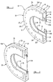
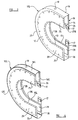
- the covers 10, 10a, 10b, 10c each comprise two spaced parallel side walls 12, 14, an outer wall 16, an open side 18 and respective aligned recesses 13, 15, which extend within each side wall from the open side 18.
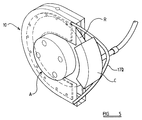
- the arrangement is such that, as shown in Figure 5, the cover may be fitted to a disc brake assembly A with the calliper C thereof received within the recesses 13, 15 and the brake rotor R enclosed within the cover.
- Drainage holes 19 (only one of which is illustrated) may be provided in the outer wall 16 to allow for the drainage of any water that may ingress while the cover is in place.
- the cover 10 comprises two pre-formed side members 20, 22, each formed from a substantially shape-holding plastics material, or possibly from a material such as cardboard, particularly corrugated cardboard.
- the side members 20, 22 in this embodiment each comprise the respective side wall 12, 14 and at their outer edges 12a, 14a a respective integrally formed lateral flange 21, 23. These flanges 21, 23 are joined together in any suitable manner along joint line 24 which is disposed on a medial plane relative to the cover as a whole to form the outer wall 16.
- joint line 24 which is disposed on a medial plane relative to the cover as a whole to form the outer wall 16.
- only one of the side members may have such a flange of correspondingly greater width to achieve the same spacing between the side walls 12, 14 with the joint then being formed at the edge of the other of said side walls.
- each side member 20, 22 is of generally C-shape with generally straight, parallel end portions 25, 26 interconnected by a respective intermediate curved portion 27, 28.
- intermediate portions 27, 28 as shown are of semi-circular shape, they could be of other shapes, and in particular the outer edges may be straight instead of semi-circular shape so that the cover as a whole is then generally of square shape apart from the recesses 13, 15.
- each side wall 12, 14 there is secured an appropriately shaped piece of kraft paper 29 impregnated with a vapour corrosion inhibitor. In some instances, however, there may be only a single piece of such paper on one of the side wall, and in other cases the impregnated paper may be provided alternatively or additionally on the inner face of the outer wall 16.
- the cover 10 can simply be slipped in place over either the brake rotor or a combination of the rotor and a dust shield of disc brake assembly, with the calliper thereof located at the outer side of the side member 20.
- self adhesive tabs 17 are secured to inward extensions 26a formed at or adjacent to the free ends of the end portions 26 of the side member 22, such that the tabs 17 can be adhered to the brake calliper.
- the cover 10a is substantially the same as that of Figure 1, but instead of the self-adhesive tabs 17, an elasticised strap 17a is secured to the side member 22 to extend between the straight end portions 26 thereof, such that the strap 17a can be stretched over the body of the brake calliper.
- a longer strap 17b is provided in the further modification shown in Figure 5 in operative position on a brake disc assembly.
- such a strap integrally with the side member, where this is made of an appropriate material.
- the covers are made from two side members 20, 22 secured together along the joint line 24, it is alternatively possible for a similar cover to be formed in one piece, for example as a moulding of a suitable light plastics material, formed possibly by blow moulding, and Figure 3 shows such an embodiment in which the side walls 12, 14 are integrally connected by the outer wall 16.
- the cover Whilst it is preferred for the cover to be made of a substantially shape-holding material, it is possible to form a similar cover from two layers of flat, flexible plastics material or the like, joined together at the outer edge to form a generally flat sleeve, which can be expanded laterally as it is applied to the disc brake rotor, and Figure 4 shows such an embodiment.
- the side walls 12c, 14c are also integrally interconnected by the outer wall 16c, but the cover is made of a suitable flexible sheet material, and instead of there being self-adhesive tabs only at the open side as in the previously described embodiments, there may be similar tabs at spaced intervals along the edges of both recesses 13c, 15c or the recesses may be made narrower by inward extensions of the side walls with adhesive material around the edges of both recesses so that the side walls overlap the calliper and adhere thereto.
Landscapes
- Engineering & Computer Science (AREA)
- General Engineering & Computer Science (AREA)
- Mechanical Engineering (AREA)
- Braking Arrangements (AREA)
Abstract
Description
Claims (15)
Applications Claiming Priority (2)
| Application Number | Priority Date | Filing Date | Title |
|---|---|---|---|
| GB9903837 | 1999-02-20 | ||
| GBGB9903837.4A GB9903837D0 (en) | 1999-02-20 | 1999-02-20 | Packaging materials |
Publications (2)
| Publication Number | Publication Date |
|---|---|
| EP1029803A2 true EP1029803A2 (en) | 2000-08-23 |
| EP1029803A3 EP1029803A3 (en) | 2000-12-20 |
Family
ID=10848112
Family Applications (1)
| Application Number | Title | Priority Date | Filing Date |
|---|---|---|---|
| EP00103555A Withdrawn EP1029803A3 (en) | 1999-02-20 | 2000-02-18 | Packaging materials |
Country Status (2)
| Country | Link |
|---|---|
| EP (1) | EP1029803A3 (en) |
| GB (2) | GB9903837D0 (en) |
Cited By (6)
| Publication number | Priority date | Publication date | Assignee | Title |
|---|---|---|---|---|
| EP1249630A3 (en) * | 2001-04-10 | 2003-03-26 | Carrs Paper Limited | Corrostion inhibition of motor vehicle components |
| WO2007060442A1 (en) * | 2005-11-25 | 2007-05-31 | Aquasol Limited | Cushion packs |
| CN104554195A (en) * | 2014-09-30 | 2015-04-29 | 太仓市上阳机械有限公司 | Simple brake device |
| ITUB20154919A1 (en) * | 2015-10-26 | 2017-04-26 | Angelo Morelli | PROTECTION DEVICE FOR DISC BRAKES |
| WO2017191338A1 (en) * | 2016-05-03 | 2017-11-09 | Javier Ortiz De Urbina Angoso | Protective element for disc brakes |
| GB2557965A (en) * | 2016-12-20 | 2018-07-04 | Trimnell Alex | Disc brake protector |
Families Citing this family (3)
| Publication number | Priority date | Publication date | Assignee | Title |
|---|---|---|---|---|
| GB0108960D0 (en) * | 2001-04-10 | 2001-05-30 | Carrs Paper Ltd | Corrosion protection of motor vehicle components |
| CN101875389B (en) * | 2010-04-02 | 2013-04-17 | 许志明 | Disk brake shield |
| WO2021160279A1 (en) * | 2020-02-14 | 2021-08-19 | Mann+Hummel Gmbh | Brake dust particle filter with water/sludge drain |
Family Cites Families (7)
| Publication number | Priority date | Publication date | Assignee | Title |
|---|---|---|---|---|
| US2746577A (en) * | 1950-06-07 | 1956-05-22 | Dunlop Rubber Co | Brake with dust shield |
| GB693919A (en) * | 1950-06-07 | 1953-07-08 | Dunlop Rubber Co | Improvements in brakes for vehicles |
| GB709305A (en) * | 1960-07-27 | 1954-05-19 | Dunlop Rubber Co | Disc brakes for vehicles |
| GB1506876A (en) * | 1975-06-20 | 1978-04-12 | Ford Motor Co | Method of protecting disc brakes from rust |
| JPS6111543Y2 (en) * | 1976-09-02 | 1986-04-11 | ||
| GB2031081A (en) * | 1978-09-01 | 1980-04-16 | British Petroleum Co | Cover for motor-vehicle disc brake |
| DE9405158U1 (en) * | 1994-03-25 | 1994-05-26 | Brender, Wolfgang, 86551 Aichach | Outer dirt protection disk cover for motor vehicle brake systems, in particular brake disk for motor vehicles provided with an integrated dirt protection disk cover |
-
1999
- 1999-02-20 GB GBGB9903837.4A patent/GB9903837D0/en not_active Ceased
-
2000
- 2000-02-17 GB GB0003565A patent/GB2346941A/en not_active Withdrawn
- 2000-02-18 EP EP00103555A patent/EP1029803A3/en not_active Withdrawn
Cited By (10)
| Publication number | Priority date | Publication date | Assignee | Title |
|---|---|---|---|---|
| EP1249630A3 (en) * | 2001-04-10 | 2003-03-26 | Carrs Paper Limited | Corrostion inhibition of motor vehicle components |
| WO2007060442A1 (en) * | 2005-11-25 | 2007-05-31 | Aquasol Limited | Cushion packs |
| CN104554195A (en) * | 2014-09-30 | 2015-04-29 | 太仓市上阳机械有限公司 | Simple brake device |
| ITUB20154919A1 (en) * | 2015-10-26 | 2017-04-26 | Angelo Morelli | PROTECTION DEVICE FOR DISC BRAKES |
| WO2017072572A1 (en) * | 2015-10-26 | 2017-05-04 | Angelo Morelli | Protection device for disc brakes |
| US10766564B2 (en) | 2015-10-26 | 2020-09-08 | Angelo Morelli | Protection device for disc brakes |
| WO2017191338A1 (en) * | 2016-05-03 | 2017-11-09 | Javier Ortiz De Urbina Angoso | Protective element for disc brakes |
| GB2557965A (en) * | 2016-12-20 | 2018-07-04 | Trimnell Alex | Disc brake protector |
| GB2557965B (en) * | 2016-12-20 | 2019-04-17 | Trimnell Alex | Disc brake protector |
| US10960948B2 (en) | 2016-12-20 | 2021-03-30 | Alex TRIMNELL | Disc brake protector |
Also Published As
| Publication number | Publication date |
|---|---|
| EP1029803A3 (en) | 2000-12-20 |
| GB2346941A (en) | 2000-08-23 |
| GB0003565D0 (en) | 2000-04-05 |
| GB9903837D0 (en) | 1999-04-14 |
Similar Documents
| Publication | Publication Date | Title |
|---|---|---|
| US4022248A (en) | Pipe having insulating material and cover and having two strips of self-sealing adhesive material | |
| US5272285A (en) | Sound attenuating machinery cover | |
| CN102057207B (en) | Non-woven, self-wrapping thermal sleeve | |
| US4994185A (en) | Combined heat shielding and bonding device for adsorbent packet in refrigerant receiver | |
| BR0008957A (en) | Injury closure system | |
| GB2336475A (en) | Flexible protective sleeve | |
| US6814105B1 (en) | Duct insulation having condensate wicking | |
| GB2346941A (en) | Cover for a disc brake assembly | |
| HK1000658B (en) | Pipe shut-off device with a sheet metal casing that may be bent around a pipe | |
| US5736211A (en) | Butt strip tape for insulation application | |
| US4207971A (en) | Rust preventing device for a rotor of a disc brake | |
| US6495228B1 (en) | Self adhesive wrapping material | |
| KR20120091334A (en) | Low profile, wrappable elongate members spacer and method of maintaining elongate members in fixed, spaced relative relation | |
| CA2097331A1 (en) | Package for individual objets | |
| JP2001503501A (en) | Auxiliary protective boots for connectable components to prevent accidents involving the driveline connecting the shaft to the universal joint or equivalent | |
| GB2254738A (en) | Cable shield strip. | |
| EP0810023A4 (en) | Blower | |
| JP3939997B2 (en) | Corrugated tube connection structure | |
| WO1997004358A1 (en) | Composite disc for the lightproff sealing of a roll of light-sensitive material | |
| DE69726814D1 (en) | Shell formed from a film with overlapping edges | |
| JP3396624B2 (en) | Pipe insulation | |
| CA2308096A1 (en) | Adhesive suture strip | |
| JPS6142826Y2 (en) | ||
| JPH02289725A (en) | Corrosion protecting device for pile | |
| JPS6125140Y2 (en) |
Legal Events
| Date | Code | Title | Description |
|---|---|---|---|
| PUAI | Public reference made under article 153(3) epc to a published international application that has entered the european phase |
Free format text: ORIGINAL CODE: 0009012 |
|
| AK | Designated contracting states |
Kind code of ref document: A2 Designated state(s): AT BE CH CY DE DK ES FI FR GB GR IE IT LI LU MC NL PT SE |
|
| AX | Request for extension of the european patent |
Free format text: AL;LT;LV;MK;RO;SI |
|
| PUAL | Search report despatched |
Free format text: ORIGINAL CODE: 0009013 |
|
| AK | Designated contracting states |
Kind code of ref document: A3 Designated state(s): AT BE CH CY DE DK ES FI FR GB GR IE IT LI LU MC NL PT SE |
|
| AX | Request for extension of the european patent |
Free format text: AL;LT;LV;MK;RO;SI |
|
| RIC1 | Information provided on ipc code assigned before grant |
Free format text: 7B 65D 85/68 A, 7F 16D 65/00 B |
|
| AKX | Designation fees paid |
Free format text: AT BE CH CY DE DK ES FI FR GB GR IE IT LI LU MC NL PT SE |
|
| STAA | Information on the status of an ep patent application or granted ep patent |
Free format text: STATUS: THE APPLICATION IS DEEMED TO BE WITHDRAWN |
|
| 18D | Application deemed to be withdrawn |
Effective date: 20010621 |