EP1029721A1 - Preassembled heat exchange unit and vehicle including such unit - Google Patents
Preassembled heat exchange unit and vehicle including such unit Download PDFInfo
- Publication number
- EP1029721A1 EP1029721A1 EP00102334A EP00102334A EP1029721A1 EP 1029721 A1 EP1029721 A1 EP 1029721A1 EP 00102334 A EP00102334 A EP 00102334A EP 00102334 A EP00102334 A EP 00102334A EP 1029721 A1 EP1029721 A1 EP 1029721A1
- Authority
- EP
- European Patent Office
- Prior art keywords
- heat exchange
- vehicle
- exchange unit
- engine
- passenger compartment
- Prior art date
- Legal status (The legal status is an assumption and is not a legal conclusion. Google has not performed a legal analysis and makes no representation as to the accuracy of the status listed.)
- Granted
Links
Images

Classifications
-
- B—PERFORMING OPERATIONS; TRANSPORTING
- B60—VEHICLES IN GENERAL
- B60H—ARRANGEMENTS OF HEATING, COOLING, VENTILATING OR OTHER AIR-TREATING DEVICES SPECIALLY ADAPTED FOR PASSENGER OR GOODS SPACES OF VEHICLES
- B60H1/00—Heating, cooling or ventilating devices
- B60H1/00007—Combined heating, ventilating, or cooling devices
- B60H1/00021—Air flow details of HVAC devices
- B60H1/00028—Constructional lay-out of the devices in the vehicle
-
- B—PERFORMING OPERATIONS; TRANSPORTING
- B60—VEHICLES IN GENERAL
- B60H—ARRANGEMENTS OF HEATING, COOLING, VENTILATING OR OTHER AIR-TREATING DEVICES SPECIALLY ADAPTED FOR PASSENGER OR GOODS SPACES OF VEHICLES
- B60H1/00—Heating, cooling or ventilating devices
- B60H1/00507—Details, e.g. mounting arrangements, desaeration devices
- B60H1/00514—Details of air conditioning housings
- B60H1/00535—Mounting or fastening of the housing to the vehicle
-
- B—PERFORMING OPERATIONS; TRANSPORTING
- B62—LAND VEHICLES FOR TRAVELLING OTHERWISE THAN ON RAILS
- B62D—MOTOR VEHICLES; TRAILERS
- B62D25/00—Superstructure or monocoque structure sub-units; Parts or details thereof not otherwise provided for
- B62D25/08—Front or rear portions
- B62D25/081—Cowls
-
- B—PERFORMING OPERATIONS; TRANSPORTING
- B60—VEHICLES IN GENERAL
- B60H—ARRANGEMENTS OF HEATING, COOLING, VENTILATING OR OTHER AIR-TREATING DEVICES SPECIALLY ADAPTED FOR PASSENGER OR GOODS SPACES OF VEHICLES
- B60H1/00—Heating, cooling or ventilating devices
- B60H1/00007—Combined heating, ventilating, or cooling devices
- B60H1/00207—Combined heating, ventilating, or cooling devices characterised by the position of the HVAC devices with respect to the passenger compartment
- B60H2001/00214—Devices in front of the passenger compartment
-
- B—PERFORMING OPERATIONS; TRANSPORTING
- B60—VEHICLES IN GENERAL
- B60S—SERVICING, CLEANING, REPAIRING, SUPPORTING, LIFTING, OR MANOEUVRING OF VEHICLES, NOT OTHERWISE PROVIDED FOR
- B60S1/00—Cleaning of vehicles
- B60S1/02—Cleaning windscreens, windows or optical devices
- B60S1/04—Wipers or the like, e.g. scrapers
- B60S1/0413—Modular wiper assembly
- B60S1/0416—Modular wiper assembly including other vehicle fittings
-
- B—PERFORMING OPERATIONS; TRANSPORTING
- B60—VEHICLES IN GENERAL
- B60S—SERVICING, CLEANING, REPAIRING, SUPPORTING, LIFTING, OR MANOEUVRING OF VEHICLES, NOT OTHERWISE PROVIDED FOR
- B60S1/00—Cleaning of vehicles
- B60S1/02—Cleaning windscreens, windows or optical devices
- B60S1/04—Wipers or the like, e.g. scrapers
- B60S1/043—Attachment of the wiper assembly to the vehicle
Definitions
- the present invention relates to a heat exchange unit for vehicles and to a motor-vehicle including such heat exchange unit.
- the invention has been developed in view of the application on motor-vehicles of the type comprising a passenger compartment, an engine compartment placed forwardly of the passenger compartment and an internal combustion engine housed in the engine compartment.
- Vehicles of this type are normally provided with a first heat exchange unit placed forwardly of the engine, in the frontal portion of the vehicle, and with a second heat exchange unit placed between the engine and the passenger compartment.
- the first heat exchange unit comprises a radiator for cooling the engine, an electric fan associated with the radiator and, for vehicles with air conditioning, a condenser included in the vehicle air conditioning system.
- the second heat exchange unit comprises a heat exchanger for heating the air flow intended to be sent to the vehicle passenger compartment, a fan unit for producing the air flow directed in the passenger compartment and a cooler in the case of vehicles with air conditioning system.
- Vehicles with a disposition of this type have various drawbacks, a first of which consists in that the components of the heat exchange system placed in the frontal part of the vehicle are subjected to breakage even in case of light front shocks.
- the radiators since in the most recent stylistic solutions the frontal part of the vehicle is constantly lower, the radiators must be lower and wider. Consequently, for creating the space necessary for the headlights it is necessary to increase both the length and the width of the frontal part of the vehicle which projects forwardly of the front axle.
- the greater dimensions of the frontal part of the vehicle increase the risk of contact with fixed obstacles during manoeuvres.
- a greater frontal width of the vehicle does not permit the adoption of an aerodynamic shape, which reduces the aerodynamic drag coefficient (CX).
- the exhaust manifold of the engine heats the motor of the fan associated with the radiator and it is necessary to leave an empty space between these elements and to introduce a thermal shield.
- the object of the present invention is to provide a heat exchange unit for vehicles which overcomes the above drawbacks.
- the numeral reference 10 schematically indicates a vehicle comprising a passenger compartment 12 and an engine compartment 14 placed forwardly of the passenger compartment.
- An internal combustion engine 16 with the respective gearbox 18 is housed in the engine compartment 14.
- a heat exchange unit 20 in accordance with the present invention is placed between the engine-gearbox assembly 16, 18 and the passenger compartment 12.
- the heat exchange unit 20 comprises an outer housing 22 of plastics material in which there are housed the components of the engine cooling system, the passenger compartment heating system and possibly of the air conditioning system.
- the heat exchange unit 20 has a front section 24 containing a radiator, a condenser, a dehydrating filter and an electric fan assembly 26.
- a radiator for heating the air flow directed in the passenger compartment
- a cooler an expansion valve and a centrifugal fan for producing the air flow directed in the passenger compartment.
- the heat exchange unit comprises also an air intake 28, a filter 30 for the air flow directed to the passenger compartment and a filter 32 for the air flow fed to the engine.
- a windscreen wiper device including a motor, a transmission mechanism and a pair of arms 32 mounted on respective oscillating pins 34 can also be mounted on the housing 22.
- a reservoir for the windshield and possibly headlights washing liquid and the engine air filter can also be mounted on the unit 20 and turn indicators and rear-view mirrors can be mounted on the outer part of the unit 20.
- the vehicle body comprises a metal wall 36 which divides the passenger compartment 12 from the engine compartment 14.
- the wall 36 is continuous and projects towards the passenger compartment.
- the heat exchange unit 20 is placed between the wall 36 and the engine-gearbox assembly 16, 18.
- An aesthetical coating 38 of the dashboard is mounted on a sheet metal structure 40.
- the coating 38 carries the traditional openings for distributing the air flow, the instruments and control and adjustment push-buttons and knobs.
- the sheet metal structure 40 on which there is mounted the aesthetical coating 38 forms a piping for distributing into the passenger compartment 12 the air flow coming from the heat exchange unit 20.
- a cross-member 42 can be provided for supporting the front portion of the heat exchange unit 20 and, at the same time, for stiffening the vehicle body.
- An element for dividing the air flow 44 can be arranged in front of the heat exchange unit 20 for conveying towards the radiator part of the air flow coming from the front portion of the vehicle.
- the element 44 may have a longitudinal wall 46 for dividing in two parts the air flow which enters into the engine compartment. The left side of the air flow (with reference to the direction of movement of the vehicle) is sent to the heat exchange unit 20, whereas the right side of the air flow is directed to the engine, the exhaust manifold and the catalytic exhaust pipe.
- a transversal wall 48 of the element 44 prevents that the flow of hot air investing the engine 16 reaches the heat exchange unit 20.
- the longitudinal wall 46 of the element 44 is preferably arranged so as to rest on the gearbox 18.
- the heat exchange unit 20 forms a completely autonomous preassembled unit comprising electric connections and connecting pipes between various components of the thermic systems and forms an integrated thermic system which carries out the functions of engine cooling system, air conditioning system and passenger compartment heating system. Since the heat exchange unit 20 is placed behind the engine 16, its component are protected by shocks on the frontal part of the vehicle and are not damaged as long as the shock does not produce the movement of the engine.
- the heat exchange unit permits to obtain a reduction of costs for repairing damages caused by frontal shocks. It permits also a reduction of weight, costs and total dimensions of thermic systems of the vehicle.
- the heat exchange unit also forms a shield which reduces the transmission of noise from the engine towards the passenger compartment of the vehicle.
- the heat exchange unit according to the invention can be designed so that the various components (radiator, condenser, electric fan, etc.) can be removed without having to remove either the engine or the aesthetic coating of the dashboard.
- the removal of components of thermic systems from the front portion of the vehicle allows the design of vehicles with a lower width of the frontal portion, with a better drag coefficient and gives the designers more freedom for creating new shapes.
Landscapes
- Engineering & Computer Science (AREA)
- Mechanical Engineering (AREA)
- Physics & Mathematics (AREA)
- Thermal Sciences (AREA)
- Chemical & Material Sciences (AREA)
- Combustion & Propulsion (AREA)
- Transportation (AREA)
- Cooling, Air Intake And Gas Exhaust, And Fuel Tank Arrangements In Propulsion Units (AREA)
- Air-Conditioning For Vehicles (AREA)
- Processing And Handling Of Plastics And Other Materials For Molding In General (AREA)
Abstract
Description
- The present invention relates to a heat exchange unit for vehicles and to a motor-vehicle including such heat exchange unit.
- The invention has been developed in view of the application on motor-vehicles of the type comprising a passenger compartment, an engine compartment placed forwardly of the passenger compartment and an internal combustion engine housed in the engine compartment. Vehicles of this type are normally provided with a first heat exchange unit placed forwardly of the engine, in the frontal portion of the vehicle, and with a second heat exchange unit placed between the engine and the passenger compartment. The first heat exchange unit comprises a radiator for cooling the engine, an electric fan associated with the radiator and, for vehicles with air conditioning, a condenser included in the vehicle air conditioning system. The second heat exchange unit comprises a heat exchanger for heating the air flow intended to be sent to the vehicle passenger compartment, a fan unit for producing the air flow directed in the passenger compartment and a cooler in the case of vehicles with air conditioning system.
- Vehicles with a disposition of this type have various drawbacks, a first of which consists in that the components of the heat exchange system placed in the frontal part of the vehicle are subjected to breakage even in case of light front shocks. Furthermore, since in the most recent stylistic solutions the frontal part of the vehicle is constantly lower, the radiators must be lower and wider. Consequently, for creating the space necessary for the headlights it is necessary to increase both the length and the width of the frontal part of the vehicle which projects forwardly of the front axle. The greater dimensions of the frontal part of the vehicle increase the risk of contact with fixed obstacles during manoeuvres. In addition, a greater frontal width of the vehicle does not permit the adoption of an aerodynamic shape, which reduces the aerodynamic drag coefficient (CX). Furthermore, the exhaust manifold of the engine heats the motor of the fan associated with the radiator and it is necessary to leave an empty space between these elements and to introduce a thermal shield. Finally, it is necessary to mount separately two distinct units.
- The object of the present invention is to provide a heat exchange unit for vehicles which overcomes the above drawbacks.
- In accordance with the present invention, this object is achieved by a heat exchange unit having the features forming the subject of the claims.
- The present invention will now be disclosed in detail with reference to the attached drawings, given purely by way of non-limiting example, in which:
- figure 1 is a plan schematic view of a vehicle provided with a heat exchange system according to the invention,
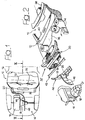
- figure 2 is an exploded perspective view of the vehicle of figure 1,
- figure 3 is a schematic cross-section taken along the line III-III of figure 1, and
- figure 4 is a schematic perspective view of the heat exchange unit indicated by the arrow IV-IV in figure 2.
- With reference to the drawings, the
numeral reference 10 schematically indicates a vehicle comprising apassenger compartment 12 and anengine compartment 14 placed forwardly of the passenger compartment. Aninternal combustion engine 16 with therespective gearbox 18 is housed in theengine compartment 14. - A
heat exchange unit 20 in accordance with the present invention is placed between the engine-gearbox assembly passenger compartment 12. Theheat exchange unit 20 comprises anouter housing 22 of plastics material in which there are housed the components of the engine cooling system, the passenger compartment heating system and possibly of the air conditioning system. In the embodiment shown in the figures, theheat exchange unit 20 has afront section 24 containing a radiator, a condenser, a dehydrating filter and anelectric fan assembly 26. In arear section 28 of theheat exchange unit 20 there are housed a radiator for heating the air flow directed in the passenger compartment, a cooler, an expansion valve and a centrifugal fan for producing the air flow directed in the passenger compartment. The heat exchange unit according to the preferred embodiment of the invention comprises also anair intake 28, a filter 30 for the air flow directed to the passenger compartment and afilter 32 for the air flow fed to the engine. A windscreen wiper device including a motor, a transmission mechanism and a pair ofarms 32 mounted on respective oscillatingpins 34 can also be mounted on thehousing 22. A reservoir for the windshield and possibly headlights washing liquid and the engine air filter can also be mounted on theunit 20 and turn indicators and rear-view mirrors can be mounted on the outer part of theunit 20. - With reference to figure 2, the vehicle body comprises a
metal wall 36 which divides thepassenger compartment 12 from theengine compartment 14. Thewall 36 is continuous and projects towards the passenger compartment. Theheat exchange unit 20 is placed between thewall 36 and the engine-gearbox assembly aesthetical coating 38 of the dashboard is mounted on asheet metal structure 40. Thecoating 38 carries the traditional openings for distributing the air flow, the instruments and control and adjustment push-buttons and knobs. Thesheet metal structure 40 on which there is mounted theaesthetical coating 38 forms a piping for distributing into thepassenger compartment 12 the air flow coming from theheat exchange unit 20. - Referring always to figure 2, a
cross-member 42 can be provided for supporting the front portion of theheat exchange unit 20 and, at the same time, for stiffening the vehicle body. An element for dividing theair flow 44 can be arranged in front of theheat exchange unit 20 for conveying towards the radiator part of the air flow coming from the front portion of the vehicle. Theelement 44 may have alongitudinal wall 46 for dividing in two parts the air flow which enters into the engine compartment. The left side of the air flow (with reference to the direction of movement of the vehicle) is sent to theheat exchange unit 20, whereas the right side of the air flow is directed to the engine, the exhaust manifold and the catalytic exhaust pipe. A transversal wall 48 of theelement 44 prevents that the flow of hot air investing theengine 16 reaches theheat exchange unit 20. As shown in figures 2 and 3, thelongitudinal wall 46 of theelement 44 is preferably arranged so as to rest on thegearbox 18. - The
heat exchange unit 20 forms a completely autonomous preassembled unit comprising electric connections and connecting pipes between various components of the thermic systems and forms an integrated thermic system which carries out the functions of engine cooling system, air conditioning system and passenger compartment heating system. Since theheat exchange unit 20 is placed behind theengine 16, its component are protected by shocks on the frontal part of the vehicle and are not damaged as long as the shock does not produce the movement of the engine. - Thus, the heat exchange unit according to the invention permits to obtain a reduction of costs for repairing damages caused by frontal shocks. It permits also a reduction of weight, costs and total dimensions of thermic systems of the vehicle. The heat exchange unit also forms a shield which reduces the transmission of noise from the engine towards the passenger compartment of the vehicle.
- The heat exchange unit according to the invention can be designed so that the various components (radiator, condenser, electric fan, etc.) can be removed without having to remove either the engine or the aesthetic coating of the dashboard. The removal of components of thermic systems from the front portion of the vehicle allows the design of vehicles with a lower width of the frontal portion, with a better drag coefficient and gives the designers more freedom for creating new shapes.
- Naturally, while the principle of the invention remains the same, the details of construction and the embodiments may be widely varied with respect to what has been disclosed and illustrated without thereby departing from the scope of the present invention.
Claims (9)
- Heat exchange unit for vehicles, characterized in that it comprises the components of the cooling system of the vehicle internal combustion engine and the components of a system for treating an air flow directed to the passenger compartment of the vehicle, said unit (20) forming a preassembled unit intended to be mounted between the engine (16) and the passenger compartment (12) of a vehicle.
- Heat exchange unit according to claim 1, characterized in that it comprises the components of a heating system and the components of an air conditioning system of the vehicle.
- Heat exchange unit according to claim 1 or 2, characterized in that it comprises also the components of a windscreen wiper assembly of the vehicle.
- Heat exchange unit according to claim 1 or 2, characterized in that it comprises also an air filter of the internal combustion engine.
- Heat exchange unit according to claim 1 or 2, characterized in that it comprises also a support for the vehicle headlights.
- Heat exchange unit according to claim 1 or 2, characterized in that it comprises also a support for the outer rear-view mirrors.
- Heat exchange unit according to claim 1 or 2, characterized in that it comprises also a support for lateral turn indicators.
- Heat exchange unit according to claim 1, characterized in that it comprises an element (44) for dividing the air flow coming from the frontal part of the vehicle, said element (44) including a longitudinal wall (46) which divides in two parallel parts the air flow entering in the engine compartment (12) of the vehicle.
- A vehicle comprising:The whole substantially as disclosed and illustrated and for the specified objects.a passenger compartment (12),an engine compartment (14) placed forwardly of the passenger compartment (12), andan internal combustion engine (16) housed in the engine compartment (12),
characterized in that it comprises a heat exchange unit (20) including the components of an engine cooling system (16) and those of a system for treating an air flow directed to the passenger compartment of the vehicle, said heat exchange unit (20) being placed between the engine (16) and the passenger compartment (12).
Applications Claiming Priority (2)
| Application Number | Priority Date | Filing Date | Title |
|---|---|---|---|
| IT1999TO000124A IT1308375B1 (en) | 1999-02-19 | 1999-02-19 | PRE-ASSEMBLED HEAT EXCHANGE GROUP AND VEHICLE EQUIPPED WITH THIS GROUP. |
| ITTO990124 | 1999-02-19 |
Publications (2)
| Publication Number | Publication Date |
|---|---|
| EP1029721A1 true EP1029721A1 (en) | 2000-08-23 |
| EP1029721B1 EP1029721B1 (en) | 2003-01-15 |
Family
ID=11417488
Family Applications (1)
| Application Number | Title | Priority Date | Filing Date |
|---|---|---|---|
| EP00102334A Expired - Lifetime EP1029721B1 (en) | 1999-02-19 | 2000-02-03 | Preassembled heat exchange unit and vehicle including such unit |
Country Status (6)
| Country | Link |
|---|---|
| US (1) | US6557772B1 (en) |
| EP (1) | EP1029721B1 (en) |
| BR (1) | BR0000649A (en) |
| DE (1) | DE60001184T2 (en) |
| ES (1) | ES2187400T3 (en) |
| IT (1) | IT1308375B1 (en) |
Cited By (4)
| Publication number | Priority date | Publication date | Assignee | Title |
|---|---|---|---|---|
| EP1308373A1 (en) * | 2001-11-06 | 2003-05-07 | Dario Di Camillo | Multi-functional container for the engine compartment of motor vehicles |
| FR2851980A1 (en) * | 2003-03-04 | 2004-09-10 | Mollertech Sas | Windshield and bonnet connecting device for motor vehicle, has transversal strut presenting sectile zone which breaks on back part of bonnet in case of impact having higher energy than predetermined value |
| EP2722257A1 (en) * | 2012-10-19 | 2014-04-23 | Mecaplast Group | Cowl module |
| JP2014156820A (en) * | 2013-02-15 | 2014-08-28 | Mitsubishi Motors Corp | Protection structure of fuel filter |
Families Citing this family (5)
| Publication number | Priority date | Publication date | Assignee | Title |
|---|---|---|---|---|
| GB2439055B (en) * | 2006-06-17 | 2009-10-14 | Agco Gmbh | Air guide in vehicle engine bay |
| TWI373672B (en) * | 2007-12-27 | 2012-10-01 | Ind Tech Res Inst | An attachment process of flexible substrate and a pattern of sealant thereof |
| DE102008021259A1 (en) * | 2008-04-29 | 2009-11-05 | Bayerische Motoren Werke Aktiengesellschaft | Motor vehicle, has bonnet limiting engine compartment on top side, where ambient air entering through inlet port is guided to lateral discharge opening formed within area of A-column of body of motor vehicle during driving |
| KR20230053393A (en) * | 2021-10-14 | 2023-04-21 | 현대자동차주식회사 | Integrated thermal management module for vehicle |
| KR102976053B1 (en) | 2021-10-15 | 2026-06-10 | 현대자동차주식회사 | Integrated thermal management module for vehicle |
Citations (5)
| Publication number | Priority date | Publication date | Assignee | Title |
|---|---|---|---|---|
| DE3110447A1 (en) * | 1981-03-18 | 1982-11-04 | Günter 8543 Hilpoltstein Elsbett | Motor vehicle, especially for conveying persons, goods, tools etc. |
| JPS61115720A (en) * | 1984-11-12 | 1986-06-03 | Yanmar Diesel Engine Co Ltd | Radiator setting structure for farm tractor |
| US4726326A (en) * | 1983-09-26 | 1988-02-23 | Charles Herbert N | Drag reducing cooling system for a vehicle |
| EP0679564A1 (en) * | 1994-04-27 | 1995-11-02 | FIAT AUTO S.p.A. | A motor vehicle structure and a method for assembling a vehicle having this structure |
| US5580122A (en) * | 1994-03-17 | 1996-12-03 | Mercedes-Benz Ag | Passenger vehicle scuttle and cockpit region construction |
Family Cites Families (11)
| Publication number | Priority date | Publication date | Assignee | Title |
|---|---|---|---|---|
| FR1388717A (en) * | 1963-10-03 | 1965-02-12 | Renault | Air conditioning system for motor vehicles |
| FR1387157A (en) * | 1963-12-04 | 1965-01-29 | Renault | Air conditioning system for motor vehicles |
| FR2615148B1 (en) * | 1987-05-12 | 1992-03-27 | Valeo | RIGID DEVICE BODY FOR A MOTOR VEHICLE HEATING SYSTEM |
| JP2566044B2 (en) * | 1990-05-25 | 1996-12-25 | 日産自動車株式会社 | Heater unit structure of vehicle air conditioner |
| US5265668A (en) * | 1991-12-02 | 1993-11-30 | Four Winds International Corporation | Heating and cooling system for vehicles |
| FR2735426B1 (en) * | 1995-06-14 | 1997-07-18 | Valeo Climatisation | DEVICE FOR HEATING-VENTILATION AND / OR AIR CONDITIONING OF THE INTERIOR OF A MOTOR VEHICLE |
| US5673964A (en) * | 1995-08-04 | 1997-10-07 | Ford Motor Company | Integral center-mounted airhandling system with integral instrument panel air-conditioning duct and structural beam |
| DE19540286A1 (en) * | 1995-10-28 | 1997-04-30 | Behr Gmbh & Co | Air conditioning for a motor vehicle |
| US5632673A (en) * | 1995-10-30 | 1997-05-27 | Chrysler Corporation | Ventilation system for lightweight automobile |
| US6059061A (en) * | 1998-07-22 | 2000-05-09 | Economoff; Peter P. | Air cooling of vehicle radiators |
| US6036594A (en) * | 1998-09-08 | 2000-03-14 | Ford Motor Company | Air handling system for automotive vehicles |
-
1999
- 1999-02-19 IT IT1999TO000124A patent/IT1308375B1/en active
-
2000
- 2000-02-03 ES ES00102334T patent/ES2187400T3/en not_active Expired - Lifetime
- 2000-02-03 EP EP00102334A patent/EP1029721B1/en not_active Expired - Lifetime
- 2000-02-03 DE DE60001184T patent/DE60001184T2/en not_active Expired - Lifetime
- 2000-02-14 US US09/504,321 patent/US6557772B1/en not_active Expired - Fee Related
- 2000-02-18 BR BR0000649-1A patent/BR0000649A/en not_active IP Right Cessation
Patent Citations (5)
| Publication number | Priority date | Publication date | Assignee | Title |
|---|---|---|---|---|
| DE3110447A1 (en) * | 1981-03-18 | 1982-11-04 | Günter 8543 Hilpoltstein Elsbett | Motor vehicle, especially for conveying persons, goods, tools etc. |
| US4726326A (en) * | 1983-09-26 | 1988-02-23 | Charles Herbert N | Drag reducing cooling system for a vehicle |
| JPS61115720A (en) * | 1984-11-12 | 1986-06-03 | Yanmar Diesel Engine Co Ltd | Radiator setting structure for farm tractor |
| US5580122A (en) * | 1994-03-17 | 1996-12-03 | Mercedes-Benz Ag | Passenger vehicle scuttle and cockpit region construction |
| EP0679564A1 (en) * | 1994-04-27 | 1995-11-02 | FIAT AUTO S.p.A. | A motor vehicle structure and a method for assembling a vehicle having this structure |
Non-Patent Citations (1)
| Title |
|---|
| PATENT ABSTRACTS OF JAPAN vol. 010, no. 301 (M - 525) 14 October 1986 (1986-10-14) * |
Cited By (6)
| Publication number | Priority date | Publication date | Assignee | Title |
|---|---|---|---|---|
| EP1308373A1 (en) * | 2001-11-06 | 2003-05-07 | Dario Di Camillo | Multi-functional container for the engine compartment of motor vehicles |
| FR2851980A1 (en) * | 2003-03-04 | 2004-09-10 | Mollertech Sas | Windshield and bonnet connecting device for motor vehicle, has transversal strut presenting sectile zone which breaks on back part of bonnet in case of impact having higher energy than predetermined value |
| EP1457395A3 (en) * | 2003-03-04 | 2006-08-02 | Mollertech | Connecting and sealing element between the windshield and the bonnet with predetermined breaking point |
| EP2722257A1 (en) * | 2012-10-19 | 2014-04-23 | Mecaplast Group | Cowl module |
| FR2997057A1 (en) * | 2012-10-19 | 2014-04-25 | Mecaplast Sa | AWNING MODULE |
| JP2014156820A (en) * | 2013-02-15 | 2014-08-28 | Mitsubishi Motors Corp | Protection structure of fuel filter |
Also Published As
| Publication number | Publication date |
|---|---|
| US6557772B1 (en) | 2003-05-06 |
| IT1308375B1 (en) | 2001-12-17 |
| ES2187400T3 (en) | 2003-06-16 |
| DE60001184D1 (en) | 2003-02-20 |
| BR0000649A (en) | 2000-10-17 |
| EP1029721B1 (en) | 2003-01-15 |
| ITTO990124A1 (en) | 2000-08-19 |
| DE60001184T2 (en) | 2003-10-09 |
Similar Documents
| Publication | Publication Date | Title |
|---|---|---|
| US5934744A (en) | Cross car structural beam | |
| US6322440B1 (en) | Outside air intake structure | |
| US5078223A (en) | Radiator device for a vehicle | |
| EP0178266B1 (en) | Motor vehicle including a preassembled subassembly formed by the power unit and a series of components of the systems of the vehicle | |
| EP1029721B1 (en) | Preassembled heat exchange unit and vehicle including such unit | |
| EP0473630A1 (en) | Automotive vehicle engine bay ventilation. | |
| US12084145B2 (en) | Off-road vehicle | |
| US3188132A (en) | Motor vehicle front end structure | |
| GB2117721A (en) | Engine cooling arrangement for motor cars | |
| GB2053822A (en) | Vehicle front end structure | |
| JPH08108741A (en) | Air conditioner for tractor with cabin | |
| JPH06328952A (en) | Vehicle engine cooling system | |
| JP2000351331A (en) | Cooling device for internal combustion engine | |
| GB2230430A (en) | Wiper drive arrangement | |
| JP3983898B2 (en) | Condenser for automotive air conditioner | |
| US6776444B2 (en) | Dashboard designed to be mounted in an interior of a vehicle, as well as to a vehicle body equipped with such a dashboard | |
| JP2006264680A (en) | Air conditioner for cabin of automobile | |
| JPH0316776Y2 (en) | ||
| JPH07172345A (en) | Vehicle front structure | |
| JPH08282305A (en) | Internal structure of an automobile engine room | |
| FR2799413A1 (en) | Air conditioning and heating system for automotive vehicle has a hollow transverse beam with air pipes running through it and radiator housed in it, which reinforces the body structure | |
| KR200307444Y1 (en) | Automotive Air Conditioning Unit | |
| JP2001063384A (en) | Automotive radiator mounting structure | |
| JPH068931Y2 (en) | Bumper structure | |
| GB2107854A (en) | Vehicle windscreen demister |
Legal Events
| Date | Code | Title | Description |
|---|---|---|---|
| PUAI | Public reference made under article 153(3) epc to a published international application that has entered the european phase |
Free format text: ORIGINAL CODE: 0009012 |
|
| AK | Designated contracting states |
Kind code of ref document: A1 Designated state(s): DE ES FR GB SE |
|
| AX | Request for extension of the european patent |
Free format text: AL;LT;LV;MK;RO;SI |
|
| 17P | Request for examination filed |
Effective date: 20000727 |
|
| AKX | Designation fees paid |
Free format text: DE ES FR GB SE |
|
| 17Q | First examination report despatched |
Effective date: 20020320 |
|
| GRAH | Despatch of communication of intention to grant a patent |
Free format text: ORIGINAL CODE: EPIDOS IGRA |
|
| RAP1 | Party data changed (applicant data changed or rights of an application transferred) |
Owner name: DENSO THERMAL SYSTEMS S.P.A. |
|
| GRAH | Despatch of communication of intention to grant a patent |
Free format text: ORIGINAL CODE: EPIDOS IGRA |
|
| GRAA | (expected) grant |
Free format text: ORIGINAL CODE: 0009210 |
|
| AK | Designated contracting states |
Kind code of ref document: B1 Designated state(s): DE ES FR GB SE |
|
| REG | Reference to a national code |
Ref country code: GB Ref legal event code: FG4D |
|
| REF | Corresponds to: |
Ref document number: 60001184 Country of ref document: DE Date of ref document: 20030220 Kind code of ref document: P |
|
| REG | Reference to a national code |
Ref country code: SE Ref legal event code: TRGR |
|
| REG | Reference to a national code |
Ref country code: ES Ref legal event code: FG2A Ref document number: 2187400 Country of ref document: ES Kind code of ref document: T3 |
|
| ET | Fr: translation filed | ||
| PLBE | No opposition filed within time limit |
Free format text: ORIGINAL CODE: 0009261 |
|
| STAA | Information on the status of an ep patent application or granted ep patent |
Free format text: STATUS: NO OPPOSITION FILED WITHIN TIME LIMIT |
|
| 26N | No opposition filed |
Effective date: 20031016 |
|
| PGFP | Annual fee paid to national office [announced via postgrant information from national office to epo] |
Ref country code: ES Payment date: 20080324 Year of fee payment: 9 |
|
| PGFP | Annual fee paid to national office [announced via postgrant information from national office to epo] |
Ref country code: DE Payment date: 20080131 Year of fee payment: 9 Ref country code: GB Payment date: 20080130 Year of fee payment: 9 Ref country code: SE Payment date: 20080219 Year of fee payment: 9 |
|
| PGFP | Annual fee paid to national office [announced via postgrant information from national office to epo] |
Ref country code: FR Payment date: 20080208 Year of fee payment: 9 |
|
| PG25 | Lapsed in a contracting state [announced via postgrant information from national office to epo] |
Ref country code: DE Free format text: LAPSE BECAUSE OF THE APPLICANT RENOUNCES Effective date: 20090216 |
|
| EUG | Se: european patent has lapsed | ||
| GBPC | Gb: european patent ceased through non-payment of renewal fee |
Effective date: 20090203 |
|
| REG | Reference to a national code |
Ref country code: FR Ref legal event code: ST Effective date: 20091030 |
|
| REG | Reference to a national code |
Ref country code: ES Ref legal event code: FD2A Effective date: 20090204 |
|
| PG25 | Lapsed in a contracting state [announced via postgrant information from national office to epo] |
Ref country code: GB Free format text: LAPSE BECAUSE OF NON-PAYMENT OF DUE FEES Effective date: 20090203 Ref country code: FR Free format text: LAPSE BECAUSE OF NON-PAYMENT OF DUE FEES Effective date: 20090302 |
|
| PG25 | Lapsed in a contracting state [announced via postgrant information from national office to epo] |
Ref country code: ES Free format text: LAPSE BECAUSE OF NON-PAYMENT OF DUE FEES Effective date: 20090204 |
|
| PG25 | Lapsed in a contracting state [announced via postgrant information from national office to epo] |
Ref country code: SE Free format text: LAPSE BECAUSE OF NON-PAYMENT OF DUE FEES Effective date: 20090204 |