EP1029491A1 - Dispositif de sécurité et/ou de commande pour appareil électrique de cuisson - Google Patents
Dispositif de sécurité et/ou de commande pour appareil électrique de cuisson Download PDFInfo
- Publication number
- EP1029491A1 EP1029491A1 EP00420036A EP00420036A EP1029491A1 EP 1029491 A1 EP1029491 A1 EP 1029491A1 EP 00420036 A EP00420036 A EP 00420036A EP 00420036 A EP00420036 A EP 00420036A EP 1029491 A1 EP1029491 A1 EP 1029491A1
- Authority
- EP
- European Patent Office
- Prior art keywords
- switch
- housing
- control means
- detection member
- called
- Prior art date
- Legal status (The legal status is an assumption and is not a legal conclusion. Google has not performed a legal analysis and makes no representation as to the accuracy of the status listed.)
- Granted
Links
- 238000010411 cooking Methods 0.000 title claims description 15
- 238000001514 detection method Methods 0.000 claims description 92
- 230000005540 biological transmission Effects 0.000 claims description 21
- 238000010438 heat treatment Methods 0.000 claims description 18
- 238000000465 moulding Methods 0.000 claims description 3
- 210000000056 organ Anatomy 0.000 claims description 3
- 230000000994 depressogenic effect Effects 0.000 description 4
- 238000010276 construction Methods 0.000 description 3
- 241001080024 Telles Species 0.000 description 1
- 238000004519 manufacturing process Methods 0.000 description 1
- 230000001846 repelling effect Effects 0.000 description 1
- 230000000284 resting effect Effects 0.000 description 1
Images


Classifications
-
- A—HUMAN NECESSITIES
- A47—FURNITURE; DOMESTIC ARTICLES OR APPLIANCES; COFFEE MILLS; SPICE MILLS; SUCTION CLEANERS IN GENERAL
- A47J—KITCHEN EQUIPMENT; COFFEE MILLS; SPICE MILLS; APPARATUS FOR MAKING BEVERAGES
- A47J37/00—Baking; Roasting; Grilling; Frying
- A47J37/12—Deep fat fryers, e.g. for frying fish or chips
- A47J37/1266—Control devices, e.g. to control temperature, level or quality of the frying liquid
Definitions
- the present invention relates to the general technical field of devices electric cooking including a cooking chamber and a mobile or removable element, such as for example a removable tank, a cover or even a door.
- the present invention relates in particular to but not exclusively electric fryers.
- the present invention relates more particularly to devices for security and / or control and these devices.
- Document GB 2 222 025 discloses a safety device and / or control of an electrical appliance comprising an enclosure associated with heating means, removably mounted on a power base.
- the device comprises at least one switch capable of closing the circuit supplying the heating means, this switch comprising a housing and an engagement button, a movable detection member between a first heating position and a second stop position, and a means of control accessible from outside the housing, movable between a first so-called “on” position and a second position called “off”.
- the device further includes a bistable actuator cooperating with the switch.
- the actuator is controlled by the detection member, the control means and a base cam surface.
- Such a construction is by design expensive when it is desired to control a switch by two members detection or control unit.
- the object of the invention is to simplify the construction of such devices electric cooking and reduce manufacturing costs.
- the switch housing is mounted free in rotation on an axis, the detection member in the "safe” position being susceptible act on the housing, respectively the button, the switch, the means of control in “on” position or the other detection member in position "safe” then being likely to act on the button, respectively the housing.
- the housing of the device is made of plastic and the axis is obtained during the molding of said housing.
- control means is mobile in rotation and includes a cam capable of actuating the "on” position button, respectively the housing, of the switch, when the detection is in the "safe” position.
- the switch housing is mounted on the control means, respectively the or one of the detection member (s), the switch button then being capable of being actuated by the detection, respectively the control means or the other member of detection.
- the actuation zone comprises a cam surface arranged perpendicular to the direction of movement of said area actuation between the position occupied by said actuation zone when on the one hand the detection member is in the "unsafe” position and on the other hand the control means is in the “off” position or that the other detection member is in the "unsafe” position, and the position occupied by said actuation zone when, on the one hand, the detection member is in position called “safe” and that on the other hand the control means is in the "on” position or that the other detection member is in the "safe” position.
- This arrangement facilitates actuation of the switch whatever either the order of actuation of the detection member and of the control means or the second detection device.
- the switch housing is fixedly mounted in the device housing and the actuation area cooperates with the button the switch when the transmission element occupies the "active" position.
- the switch housing is mounted mobile in the housing of the device and the actuation zone cooperates with the housing of the switch to push the switch button against a stop of the housing when the transmission element occupies the "active" position.
- the switch housing is mounted movable in rotation around an axis disposed in the housing of the device.
- control means is likely to occupy several "on" positions.
- the control means is advantageously formed by the button control of a thermostat with adjustable set temperature, this construction avoiding specialized control means for the switch On Off.
- Figure 1 shows a control and safety device in an appliance electric cooking comprising a housing 1 forming a housing provided for receive a removable tank 2.
- the housing has an inner wall 10 delimiting the housing for receiving the tank 2 and an outer wall 11 for housing between said wall and the inner wall 10 of the bodies such than a thermostat or a thermal fuse.
- the control and safety device comprises a detection member 4 presence of the tank 2.
- the detection member 4 is disposed in the housing 1 between the walls 10 and 11.
- the detection member 4 comprises a rod 12 mounted sliding in the housing 1.
- the rod 12 carries a lug 13 provided to cooperate with the inverted edge 3 of the tank 2 and a tab 9 provided to cooperate with a switch 6.
- the lug 13 thus forms a detection zone for the tank 2 and the tab 9 forms an actuation zone of the switch 6.
- FIG. 2 shows the detection member 4 mounted mobile against a return means 5.
- the detection member 4 occupies a first pressed position in which the switch 6 is capable of close the supply circuit for the appliance's heating means (no shown in the figures).
- the detection member 4 occupies a second position raised, in which the switch 6 cuts off the supply of the means of heated. This position corresponds to the recall position.
- the switch 6 is associated with a control means 15 accessible from the exterior of the housing 1, said control means being capable of occupying an "on” position in which the switch 6 is capable of cooperate with the actuation area of the presence detection member 4 of the tank 2 to close the supply circuit of the device, and a position "stop” in which the switch 6 opens said supply circuit.
- control means 15 is formed by a wheel carrying a cam 16 rotatably mounted in the housing 1 on an axis 14 carrying an operating button 7 accessible to the user.
- Switch 6 is advantageously mounted free to rotate on an axis 8 from the housing 1.
- the tab 9 switches the switch 6 between the first and the second position.
- the housing 1 is made of plastic and the axis 8 is obtained during the molding of the housing 1.
- the switch 6 has a housing switch 20 and a switch button 17 capable of cooperating with the cam 16.
- the switch button 17 could cooperate with the leg 9 of the detection member 4, the switch housing 20 then cooperating with the cam 16.
- the means of command 15 could be movable in translation and command for example axis 14 via a rack.
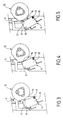
- the detection member 4 occupies the position in which the tank 2 (not shown in the figure) is present and the control means 15 occupies the "off" position.
- the switch housing 20 comes to bear against the tab 9 and the switch button 17 occupies a raised position in which the circuit power is open.
- the detection member 4 also occupies the position in which tank 2 (not shown in the figure) is present, but the control means 15 occupies the "on” position.
- the switch housing 20 comes to bear against tab 9 and switch button 17 pushed back by cam 16 occupies a depressed position in which the supply circuit is closed.
- the cam 16 extends over the periphery of the wheel which allows to consider several "on” positions for the control means 15, this control means which can for example be associated with the adjustment button the setpoint of a thermostat with variable setpoint temperature.
- the detection member 4 occupies the position in which the tank 2 (not shown in the figure) is missing or improperly positioned and the means of control 15 occupies the "on" position.
- the switch box 20 comes resting against a beveled end 19 of the tab 9 and the button switch 17 occupies a raised position in which the circuit power is open.
- the tab 9 blocks the switch 6 and the switch button 17 is pressed, thereby closing the electrical circuit.
- the detection member 4 is moved against the return means 5 and the tab 9 pushes the switch 6 against the cam 16.
- the switch button 17 is then pressed and the circuit electric is closed.
- the device can work.
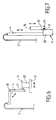
- the detection member 4 'of presence of the tank 2 is mounted mobile in rotation on an axis 18 from the housing (not shown in the figure) against a return means (not shown in the figure) and the control means 15 ′ is movable laterally between a "on" position and "off” position.
- the 20 'box of the 6' switch is mounted on the control means 15 '. The electrical circuit is closed when the switch button 17 'is in the depressed position and is open when the switch button 17 'is in the raised position.
- the 4 "detection member of presence of tank 2 is movable vertically against a return spring (not shown in the figure) and the 15 "control means is movable vertically.
- the housing 20 “of the switch 6" is mounted on the 4 “detection. The electrical circuit is closed when the 17" switch button is in the raised position and is open when the 17 "switch button is in position pressed.
- the control means 15 is likely to occupy a "off” position 22 in which the switch button 17 “is in position pressed and an "on” position 21, for which the switch button 17 "occupies a raised position in the presence of the tank 2 in the housing, such that shown in Figure 7, the housing receiving the tank is not shown, and a position pressed in the absence of a tank.
- the housing 101 belongs to an electric cooking appliance comprising a tank 102 removable.
- a detection member 104 is mounted movable in translation in the housing 101.
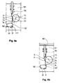
- the detection member 104 comprises a rod 112 slidingly mounted in the housing 101 against a return means 105 between a raised position, corresponding to the return position, shown in Figures 8a and 8c, and a lowered position when the tank 102 is in place in the housing, corresponding to Figures 8b and 8d.
- the tank 102 in place in the housing 101 pushes the detection member 104 against the return means 105.
- the position raised by the detection device 104 corresponds to the "unsafe" position and the lowered position of the detection member 104 corresponds to the "safe" position.
- a control means 115 is mounted mobile in rotation in the housing 101 between a first position called “stop”, shown in FIGS. 8a and 8b, and a second position called “on”, shown in Figures 8c and 8d. Way to control 115 has a circular periphery portion 25 adjacent to a flat 26.
- the control means 115 can occupy other positions "step”, not shown in the figures. Note that the periphery of the means of command 115 is circular outside the flat 26 which allows to consider several "on" positions for the control means 115, this control means which can for example be associated with the adjustment button the setpoint of a thermostat with variable setpoint temperature.
- a transmission element 31 is associated with the detection member 104.
- the transmission element 31 is formed by a flexible piece comprising a fixed part 32 mounted on the rod 112 and a mobile part 33.
- the mobile part 33 includes a control area 34 capable of cooperating with the control means 115 and an actuation zone 35 capable of cooperate with a switch 106 mounted in the housing 101.
- the switch 106 comprises a switch box 120 fixedly mounted in the housing 101 and a switch button 117 capable of cooperating with the actuation area 35.
- the actuation area 35 has a surface of cam 36 arranged perpendicular to the direction of movement of said cam zone between on the one hand the position occupied when the detection member 104 is in the "unsafe” position and the control means 115 in the "off” position, represented in FIG. 8a, and on the other hand the position occupied when the member detection 104 is in the "safe” position and the control means 115 in “on” position shown in FIG. 8d, so as to facilitate actuation of the switch button 117.
- the operation of this exemplary embodiment is as follows.
- the organ of detection 104 moves the transmission element 31 according to a first substantially vertical direction and the control means 115 moves the transmission element 31 in a second direction substantially horizontal.
- the transmission element 31 is in the raised position when the detection 104 is in the raised position, as shown in FIGS. 8a and 8c, and in lowered position when the detection member 104 is in the lowered position in the presence of the tank 102, as shown in Figures 8b and 8d.
- the transmission element 31 is in the non-pushed back position when the flat 26 cooperates with the control area 34, as shown in FIGS. 8a and 8b, and in the pushed back position when the circular periphery portion 25 cooperates with the control area 34, as shown in Figures 8c and 8d.
- the transmission element 31 cooperates with the switch button 117 when the detection member 104 is in the "safe” position and the means of control 115 is in the “on” position, as shown in FIG. 8d. The transmission element 31 is then in the "active" position.
- the transmission element 31 does not cooperate with the switch button 117 when the detection member 104 is in the "unsafe” position or the means 115 is in the “off” position, as shown in FIGS. 8a to 8c.
- the embodiment shown in Figures 9a and 9b differs from the example previous in that the switch 106 'has a switch box 120' mobile mounted in the housing 101 and a switch button 117 'capable to cooperate with a stop 37 of the housing 101.
- the actuation area 35 is capable of cooperating with the switch housing 120 ′ mounted mobile in rotation on an axis 38.
- the actuation area 35 pushes the switch housing 120 ' towards the switch button 117 'coming to bear against the stop 37.
- the actuation area 35 releases the switch housing 120 'and the switch button 117 'can take its rest position.
- the actuation zone 35 has a cam surface 36 arranged perpendicular to the direction of movement of said area between one leaves the position occupied when the detection member 104 is in the "no" position safe “and the control means 115 in the” off “position, shown in FIG. 9a, and on the other hand the position occupied when the detection member 104 is in “safe” position and the control means 115 in “on” position shown in Figure 9b, so as to facilitate the pivoting of the housing switch 120 'around axis 38 to activate the switch button 117 against the stop 37.
- the control means and the detection member can be movable between two positions with a movement different from a rotational movement or of a translational movement.
- control means can be replaced by another detection device.
Landscapes
- Engineering & Computer Science (AREA)
- Food Science & Technology (AREA)
- Cookers (AREA)
- Electric Stoves And Ranges (AREA)
- Control Of Resistance Heating (AREA)
- Frying-Pans Or Fryers (AREA)
Abstract
Description
- au moins un interrupteur apte à fermer le circuit d'alimentation des moyens de chauffe, cet interrupteur comportant un boítier et un bouton d'enclenchement,
- un ou plusieurs organe(s) de détection, chacun étant mobile entre une première position dite "sûre" correspondant à une configuration prédéterminée de mise en oeuvre de l'appareil et une deuxième position dite "non sûre" correspondant à une autre configuration dans laquelle l'appareil ne doit pas être mis en oeuvre,
- si désiré un moyen de commande accessible de l'extérieur du boítier de l'appareil, mobile entre une première position dite "marche" et une deuxième position dite "arrêt",
- au moins un interrupteur apte à fermer le circuit d'alimentation des moyens de chauffe, cet interrupteur comportant un boítier et un bouton d'enclenchement,
- un ou plusieurs organe(s) de détection, chacun étant mobile entre une première position dite "sûre" correspondant à une configuration prédéterminée de mise en oeuvre de l'appareil et une deuxième position dite "non sûre" correspondant à une autre configuration dans laquelle l'appareil ne doit pas être mis en oeuvre,
- si désiré un moyen de commande accessible de l'extérieur du boítier, mobile entre une première position dite "marche" et une deuxième position dite "arrêt",
- la figure 1 montre une vue en éclaté d'un premier exemple de réalisation d'un dispositif selon l'invention,
- la figure 2 est une vue en coupe de la partie supérieure du dispositif montré à la figure 1,
- les figures 3 à 5 montrent trois positions de fonctionnement du dispositif montré aux figures 1 et 2,
- la figure 6 est une vue schématique d'un deuxième exemple de réalisation d'un dispositif selon l'invention,
- la figure 7 est une vue schématique d'un troisième exemple de réalisation d'un dispositif selon l'invention,
- les figures 8a à 8d sont des vues schématiques d'un quatrième exemple de réalisation d'un dispositif selon l'invention,
- les figures 9a et 9b sont des vues schématiques d'un cinquième exemple de réalisation d'un dispositif selon l'invention,
Claims (12)
- Dispositif de sécurité et /ou de commande d'un appareil électrique de cuisson comportant dans un boítier (1) une enceinte de cuisson (2) et des moyens de chauffe de l'enceinte, ledit dispositif comportantcaractérisé en ce queau moins un interrupteur (6) apte à fermer le circuit d'alimentation des moyens de chauffe, cet interrupteur comportant un boítier (20) et un bouton d'enclenchement (17),un ou plusieurs organe(s) de détection (4), chacun étant mobile entre une première position dite "sûre" correspondant à une configuration prédéterminée de mise en oeuvre de l'appareil et une deuxième position dite "non sûre" correspondant à une autre configuration dans laquelle l'appareil ne doit pas être mis en oeuvre,si désiré un moyen de commande (15) accessible de l'extérieur du boítier, mobile entre une première position dite "marche" et une deuxième position dite "arrêt",
le boítier (20) de l'interrupteur est monté mobile de telle sorte à être susceptible d'être déplacé par le moyen de commande (15) passant en sa position "marche", respectivement le ou l'un des organe(s) de détection (4), d'une première position de boítier dite "non active" dans laquelle l'interrupteur (6) est en un état ouvert ou fermé à une seconde position dite "active" dans laquelle l'interrupteur est basculé dans son autre état fermé ou ouvert par l'organe de détection (4) passant en sa position "sûre", respectivement le moyen de commande (15) passant en sa position "marche" ou l'autre organe de détection passant en sa position "sûre". - Dispositif selon la revendication 1, caractérisé en ce que le boítier (20) de l'interrupteur (6) est monté libre en rotation sur un axe (8), l'organe de détection (4) en position "sûre" étant susceptible d'agir sur le boítier (20), respectivement le bouton (17), de l'interrupteur (6), le moyen de commande (15) en position "marche" ou l'autre organe de détection en position "sûre" étant alors susceptible d'agir sur le bouton (17), respectivement le boítier (20).
- Dispositif selon la revendication 2, caractérisé en ce que le boítier (1) est réalisé en matière plastique et en ce que l'axe (8) est obtenu lors du moulage du boítier (1).
- Dispositif selon la revendication 3, caractérisé en ce que le moyen de commande (15) est mobile en rotation et comporte une came (16) susceptible en position "marche" d'actionner le bouton (17), respectivement le boítier (20), de l'interrupteur (6), lorsque l'organe de détection (4) est en position "sûre".
- Dispositif selon l'une des revendications 1 à 4, caractérisé en ce que le boítier (20) de l'interrupteur (6) est monté sur le moyen de commande (15), respectivement le ou sur l'un des organe(s) de détection (4), le bouton (17) de l'interrupteur (6) étant alors susceptible d'être actionné par l'organe de détection (4), respectivement le moyen de commande (15) ou l'autre organe de détection.
- Dispositif de sécurité et/ou de commande d'un appareil électrique de cuisson comportant dans un boítier (101) une enceinte de cuisson (102) et des moyens de chauffe de l'enceinte, ledit dispositif comportantcaractérisé en ce qu'un élément de transmission (31) monté sur l'organe de détection (104), respectivement le moyen de commande, présente une partie mobile (33) comprenant une zone de commande (34), déplaçable par le moyen de commande (115) ou un autre organe de détection, respectivement l'organe de détection, et une zone d'actionnement (35) susceptible de coopérer avec l'interrupteur (106 ; 106') lorsque d'une part l'organe de détection (104) est en position dite "sûre" et que d'autre part le moyen de commande (115) est en position "marche" ou que l'autre organe de détection est en position dite "sûre", l'élément de transmission (31) occupant alors une position dite "active" dans laquelle l'interrupteur (106 ; 106') est dans un état ouvert ou fermé, l'interrupteur (106 ; 106') étant dans son autre état fermé ou ouvert lorsque l'organe de détection (104) est en position dite "non sûre" ou que le moyen de commande (115) est en position "arrêt" ou que l'autre organe de détection est en position dite "non sûre", la zone d'actionnement (35) n'étant alors pas susceptible de coopérer avec l'interrupteur (106 ; 106').au moins un interrupteur (106 ; 106') apte à fermer le circuit d'alimentation des moyens de chauffe, cet interrupteur comportant un boítier (120 ; 120') et un bouton d'enclenchement (117 ; 117'),un ou plusieurs organe(s) de détection (104), chacun étant mobile entre une première position dite "sûre" correspondant à une configuration prédéterminée de mise en oeuvre de l'appareil et une deuxième position dite "non sûre" correspondant à une autre configuration dans laquelle l'appareil ne doit pas être mis en oeuvre,si désiré un moyen de commande (115) accessible de l'extérieur du boítier, mobile entre une première position dite "marche" et une deuxième position dite "arrêt",
- Dispositif selon la revendication 6, caractérisé en ce que la zone d'actionnement (35) comporte une surface de came (36) disposée perpendiculairement à la direction du déplacement de ladite zone d'actionnement entre la position occupée par ladite zone d'actionnement lorsque d'une part l'organe de détection (104) est en position "non sûre" et que d'autre part le moyen de commande (115) est en position "arrêt" ou que l'autre organe de détection est en position "non sûre", et la position occupée par ladite zone d'actionnement lorsque d'une part l'organe de détection (104) est en position "sûre" et que d'autre part le moyen de commande (115) est en position "marche" ou que l'autre organe de détection est en position "sûre".
- Dispositif selon l'une des revendications 6 ou 7, caractérisé en ce que le boítier (120) de l'interrupteur (106) est monté fixe dans le boítier (101) de l'appareil et que la zone d'actionnement (35) coopère avec le bouton (117) de l'interrupteur (106) lorsque l'élément de transmission (31) occupe la position "active".
- Dispositif selon l'une des revendications 6 ou 7, caractérisé en ce que le boítier (120') de l'interrupteur (106') est monté mobile dans le boítier (101) de l'appareil et que la zone d'actionnement (35) coopère avec le boítier (120') de l'interrupteur (106') pour repousser le bouton (117') de l'interrupteur (106') contre une butée (37) du boítier (101) lorsque l'élément de transmission (31) occupe la position "active".
- Dispositif selon la revendication 9, caractérisé en ce que le boítier (120') de l'interrupteur (106') est monté mobile en rotation autour d'un axe (38) disposé dans le boítier (101) de l'appareil.
- Dispositif selon l'une des revendications 1 à 10, caractérisé en ce que le moyen de commande (15 ; 115) est susceptible d'occuper plusieurs positions " marche" .
- Dispositif selon l'une des revendications 1 à 11, caractérisé en ce que le moyen de commande (15 ; 115) est formé par le bouton de commande d'un thermostat à température de consigne réglable.
Applications Claiming Priority (2)
| Application Number | Priority Date | Filing Date | Title |
|---|---|---|---|
| FR9902260A FR2789871B1 (fr) | 1999-02-19 | 1999-02-19 | Dispositif de securite et/ou de commande pour appareil electrique de cuisson |
| FR9902260 | 1999-02-19 |
Publications (2)
| Publication Number | Publication Date |
|---|---|
| EP1029491A1 true EP1029491A1 (fr) | 2000-08-23 |
| EP1029491B1 EP1029491B1 (fr) | 2004-01-21 |
Family
ID=9542444
Family Applications (1)
| Application Number | Title | Priority Date | Filing Date |
|---|---|---|---|
| EP00420036A Expired - Lifetime EP1029491B1 (fr) | 1999-02-19 | 2000-02-17 | Dispositif de sécurité et/ou de commande pour appareil électrique de cuisson |
Country Status (8)
| Country | Link |
|---|---|
| US (1) | US6268591B1 (fr) |
| EP (1) | EP1029491B1 (fr) |
| CN (1) | CN1158040C (fr) |
| AT (1) | ATE258023T1 (fr) |
| DE (1) | DE60007785T2 (fr) |
| DK (1) | DK1029491T3 (fr) |
| ES (1) | ES2211482T3 (fr) |
| FR (1) | FR2789871B1 (fr) |
Families Citing this family (3)
| Publication number | Priority date | Publication date | Assignee | Title |
|---|---|---|---|---|
| US7128275B2 (en) * | 2004-08-24 | 2006-10-31 | C Change Surgical Llc | Liquid warming device with basin |
| SG10201503914RA (en) * | 2015-05-19 | 2016-12-29 | Advanced Nutraceutical Pte Ltd | A baking machine |
| US12290332B2 (en) | 2018-11-16 | 2025-05-06 | WEG Surgical Solutions, LLC | Air gap detectors in heating system for draped basin |
Citations (4)
| Publication number | Priority date | Publication date | Assignee | Title |
|---|---|---|---|---|
| GB2055248A (en) * | 1979-05-01 | 1981-02-25 | Delta Materials Research Ltd | Electric liquid heating containers |
| GB2222025A (en) * | 1988-08-01 | 1990-02-21 | Strix Ltd | Liquid heating container |
| EP0528656A1 (fr) * | 1991-08-12 | 1993-02-24 | Strix Limited | Bouillaires |
| WO1996005761A1 (fr) * | 1994-08-22 | 1996-02-29 | Seb S.A. | Securite electrique pour appareil de chauffe pour aliments |
Family Cites Families (2)
| Publication number | Priority date | Publication date | Assignee | Title |
|---|---|---|---|---|
| US4164644A (en) * | 1978-08-07 | 1979-08-14 | Courtesy Interstate Corporation | Portable electrical heating unit with automatic cutoff |
| US5823095A (en) * | 1997-02-25 | 1998-10-20 | Walker; Shannon | Automatic shut-off device for coffee maker |
-
1999
- 1999-02-19 FR FR9902260A patent/FR2789871B1/fr not_active Expired - Fee Related
-
2000
- 2000-02-17 AT AT00420036T patent/ATE258023T1/de not_active IP Right Cessation
- 2000-02-17 DE DE60007785T patent/DE60007785T2/de not_active Expired - Fee Related
- 2000-02-17 DK DK00420036T patent/DK1029491T3/da active
- 2000-02-17 EP EP00420036A patent/EP1029491B1/fr not_active Expired - Lifetime
- 2000-02-17 ES ES00420036T patent/ES2211482T3/es not_active Expired - Lifetime
- 2000-02-18 CN CNB001046926A patent/CN1158040C/zh not_active Expired - Fee Related
- 2000-02-22 US US09/510,222 patent/US6268591B1/en not_active Expired - Fee Related
Patent Citations (4)
| Publication number | Priority date | Publication date | Assignee | Title |
|---|---|---|---|---|
| GB2055248A (en) * | 1979-05-01 | 1981-02-25 | Delta Materials Research Ltd | Electric liquid heating containers |
| GB2222025A (en) * | 1988-08-01 | 1990-02-21 | Strix Ltd | Liquid heating container |
| EP0528656A1 (fr) * | 1991-08-12 | 1993-02-24 | Strix Limited | Bouillaires |
| WO1996005761A1 (fr) * | 1994-08-22 | 1996-02-29 | Seb S.A. | Securite electrique pour appareil de chauffe pour aliments |
Also Published As
| Publication number | Publication date |
|---|---|
| EP1029491B1 (fr) | 2004-01-21 |
| CN1270789A (zh) | 2000-10-25 |
| DK1029491T3 (da) | 2004-06-01 |
| CN1158040C (zh) | 2004-07-21 |
| ATE258023T1 (de) | 2004-02-15 |
| DE60007785D1 (de) | 2004-02-26 |
| FR2789871B1 (fr) | 2001-05-18 |
| ES2211482T3 (es) | 2004-07-16 |
| FR2789871A1 (fr) | 2000-08-25 |
| US6268591B1 (en) | 2001-07-31 |
| DE60007785T2 (de) | 2004-12-02 |
Similar Documents
| Publication | Publication Date | Title |
|---|---|---|
| EP1551261B1 (fr) | La bouilloire electrique | |
| EP2687132B1 (fr) | Appareil de cuisson d'aliments sous pression à dispositif de commande amélioré | |
| EP3756514A1 (fr) | Appareil de cuisson électrique pourvu d'un dispositif de chauffage démontable | |
| EP0275785B1 (fr) | Appareil électro-ménager combinant grille-pain et four | |
| EP0993264A1 (fr) | Appareil electromenager pour le traitement des aliments comportant un dispositif de securite | |
| EP0777434B1 (fr) | Securite electrique pour appareil de chauffe pour aliments | |
| CA2210327A1 (fr) | Appareil menager a couteau rotatif, tel qu'un hachoir | |
| EP1011401B1 (fr) | Appareil electromenager pour la preparation d'aliments comportant un dispositif de securite | |
| EP2433533B1 (fr) | Appareil électroménager de préparation culinaire comportant un récipient renfermant un outil coupant entraîné en rotation par un moteur | |
| EP2433534B1 (fr) | Appareil électroménager de préparation culinaire comportant un récipient renfermant un outil coupant entraîné en rotation par un moteur | |
| EP1029491B1 (fr) | Dispositif de sécurité et/ou de commande pour appareil électrique de cuisson | |
| EP1734850B1 (fr) | Appareil electrique de chauffage de liquide | |
| EP4014808B1 (fr) | Appareil de cuisson électrique pour la cuisson de produits alimentaires | |
| EP2368469A1 (fr) | Appareil électroménager de préparation culinaire comportant un boitier moteur destiné à recevoir différents types d'accessoires amovibles | |
| EP0129222A2 (fr) | Dispositif de commande d'un appareil électroménager | |
| EP1370171B1 (fr) | Appareil electromenager de preparation culinaire comportant un outil rotatif et un double dispositif de securite | |
| EP2061060B1 (fr) | Appareil électrique de coupure tel un disjoncteur ou un interrupteur | |
| FR2889129A1 (fr) | Porte-recipient pour vehicule automobile | |
| WO2006077330A1 (fr) | Appareil electromenager comprenant un dispositif de securite triple action | |
| EP1151835B1 (fr) | Appareil électrique de traitement d'aliments comportant un organe presseur | |
| FR2623885A1 (fr) | Table de cuisson | |
| EP1169959A1 (fr) | Appareil electrique de cuisson comportant une cuve amovible |
Legal Events
| Date | Code | Title | Description |
|---|---|---|---|
| PUAI | Public reference made under article 153(3) epc to a published international application that has entered the european phase |
Free format text: ORIGINAL CODE: 0009012 |
|
| AK | Designated contracting states |
Kind code of ref document: A1 Designated state(s): AT BE CH CY DE DK ES FI FR GB GR IE IT LI LU MC NL PT SE |
|
| AX | Request for extension of the european patent |
Free format text: AL;LT;LV;MK;RO;SI |
|
| 17P | Request for examination filed |
Effective date: 20001222 |
|
| AKX | Designation fees paid |
Free format text: AT BE CH CY DE DK ES FI FR GB GR IE IT LI LU MC NL PT SE |
|
| 17Q | First examination report despatched |
Effective date: 20020916 |
|
| GRAH | Despatch of communication of intention to grant a patent |
Free format text: ORIGINAL CODE: EPIDOS IGRA |
|
| GRAS | Grant fee paid |
Free format text: ORIGINAL CODE: EPIDOSNIGR3 |
|
| GRAA | (expected) grant |
Free format text: ORIGINAL CODE: 0009210 |
|
| AK | Designated contracting states |
Kind code of ref document: B1 Designated state(s): AT BE CH CY DE DK ES FI FR GB GR IE IT LI LU MC NL PT SE |
|
| PG25 | Lapsed in a contracting state [announced via postgrant information from national office to epo] |
Ref country code: IE Free format text: LAPSE BECAUSE OF FAILURE TO SUBMIT A TRANSLATION OF THE DESCRIPTION OR TO PAY THE FEE WITHIN THE PRESCRIBED TIME-LIMIT Effective date: 20040121 Ref country code: FI Free format text: LAPSE BECAUSE OF FAILURE TO SUBMIT A TRANSLATION OF THE DESCRIPTION OR TO PAY THE FEE WITHIN THE PRESCRIBED TIME-LIMIT Effective date: 20040121 Ref country code: CY Free format text: LAPSE BECAUSE OF FAILURE TO SUBMIT A TRANSLATION OF THE DESCRIPTION OR TO PAY THE FEE WITHIN THE PRESCRIBED TIME-LIMIT Effective date: 20040121 |
|
| REG | Reference to a national code |
Ref country code: GB Ref legal event code: FG4D Free format text: NOT ENGLISH |
|
| REG | Reference to a national code |
Ref country code: CH Ref legal event code: EP |
|
| PG25 | Lapsed in a contracting state [announced via postgrant information from national office to epo] |
Ref country code: LU Free format text: LAPSE BECAUSE OF NON-PAYMENT OF DUE FEES Effective date: 20040217 |
|
| REG | Reference to a national code |
Ref country code: IE Ref legal event code: FG4D Free format text: FRENCH |
|
| REF | Corresponds to: |
Ref document number: 60007785 Country of ref document: DE Date of ref document: 20040226 Kind code of ref document: P |
|
| PG25 | Lapsed in a contracting state [announced via postgrant information from national office to epo] |
Ref country code: MC Free format text: LAPSE BECAUSE OF NON-PAYMENT OF DUE FEES Effective date: 20040228 |
|
| REG | Reference to a national code |
Ref country code: CH Ref legal event code: NV Representative=s name: MOINAS & SAVOYE SA |
|
| PG25 | Lapsed in a contracting state [announced via postgrant information from national office to epo] |
Ref country code: SE Free format text: LAPSE BECAUSE OF FAILURE TO SUBMIT A TRANSLATION OF THE DESCRIPTION OR TO PAY THE FEE WITHIN THE PRESCRIBED TIME-LIMIT Effective date: 20040421 |
|
| GBT | Gb: translation of ep patent filed (gb section 77(6)(a)/1977) |
Effective date: 20040421 |
|
| REG | Reference to a national code |
Ref country code: GR Ref legal event code: EP Ref document number: 20040401195 Country of ref document: GR |
|
| REG | Reference to a national code |
Ref country code: DK Ref legal event code: T3 |
|
| REG | Reference to a national code |
Ref country code: ES Ref legal event code: FG2A Ref document number: 2211482 Country of ref document: ES Kind code of ref document: T3 |
|
| REG | Reference to a national code |
Ref country code: IE Ref legal event code: FD4D |
|
| PLBE | No opposition filed within time limit |
Free format text: ORIGINAL CODE: 0009261 |
|
| STAA | Information on the status of an ep patent application or granted ep patent |
Free format text: STATUS: NO OPPOSITION FILED WITHIN TIME LIMIT |
|
| 26N | No opposition filed |
Effective date: 20041022 |
|
| PG25 | Lapsed in a contracting state [announced via postgrant information from national office to epo] |
Ref country code: IT Free format text: LAPSE BECAUSE OF NON-PAYMENT OF DUE FEES;WARNING: LAPSES OF ITALIAN PATENTS WITH EFFECTIVE DATE BEFORE 2007 MAY HAVE OCCURRED AT ANY TIME BEFORE 2007. THE CORRECT EFFECTIVE DATE MAY BE DIFFERENT FROM THE ONE RECORDED. Effective date: 20050217 |
|
| PG25 | Lapsed in a contracting state [announced via postgrant information from national office to epo] |
Ref country code: PT Free format text: LAPSE BECAUSE OF NON-PAYMENT OF DUE FEES Effective date: 20040621 |
|
| PGFP | Annual fee paid to national office [announced via postgrant information from national office to epo] |
Ref country code: CH Payment date: 20080228 Year of fee payment: 9 Ref country code: DK Payment date: 20080226 Year of fee payment: 9 |
|
| PGFP | Annual fee paid to national office [announced via postgrant information from national office to epo] |
Ref country code: GR Payment date: 20071219 Year of fee payment: 9 |
|
| PGFP | Annual fee paid to national office [announced via postgrant information from national office to epo] |
Ref country code: AT Payment date: 20080226 Year of fee payment: 9 |
|
| PGFP | Annual fee paid to national office [announced via postgrant information from national office to epo] |
Ref country code: ES Payment date: 20090127 Year of fee payment: 10 |
|
| PGFP | Annual fee paid to national office [announced via postgrant information from national office to epo] |
Ref country code: DE Payment date: 20090219 Year of fee payment: 10 Ref country code: NL Payment date: 20081125 Year of fee payment: 10 |
|
| PGFP | Annual fee paid to national office [announced via postgrant information from national office to epo] |
Ref country code: GB Payment date: 20081231 Year of fee payment: 10 |
|
| PGFP | Annual fee paid to national office [announced via postgrant information from national office to epo] |
Ref country code: BE Payment date: 20090205 Year of fee payment: 10 |
|
| REG | Reference to a national code |
Ref country code: CH Ref legal event code: PL |
|
| REG | Reference to a national code |
Ref country code: DK Ref legal event code: EBP |
|
| PG25 | Lapsed in a contracting state [announced via postgrant information from national office to epo] |
Ref country code: AT Free format text: LAPSE BECAUSE OF NON-PAYMENT OF DUE FEES Effective date: 20090217 Ref country code: CH Free format text: LAPSE BECAUSE OF NON-PAYMENT OF DUE FEES Effective date: 20090228 Ref country code: LI Free format text: LAPSE BECAUSE OF NON-PAYMENT OF DUE FEES Effective date: 20090228 |
|
| PG25 | Lapsed in a contracting state [announced via postgrant information from national office to epo] |
Ref country code: GR Free format text: LAPSE BECAUSE OF NON-PAYMENT OF DUE FEES Effective date: 20090902 |
|
| PGFP | Annual fee paid to national office [announced via postgrant information from national office to epo] |
Ref country code: IT Payment date: 20090227 Year of fee payment: 10 |
|
| PGRI | Patent reinstated in contracting state [announced from national office to epo] |
Ref country code: IT Effective date: 20091201 |
|
| PG25 | Lapsed in a contracting state [announced via postgrant information from national office to epo] |
Ref country code: DK Free format text: LAPSE BECAUSE OF NON-PAYMENT OF DUE FEES Effective date: 20090831 |
|
| BERE | Be: lapsed |
Owner name: S.A. *SEB Effective date: 20100228 |
|
| REG | Reference to a national code |
Ref country code: NL Ref legal event code: V1 Effective date: 20100901 |
|
| GBPC | Gb: european patent ceased through non-payment of renewal fee |
Effective date: 20100217 |
|
| PG25 | Lapsed in a contracting state [announced via postgrant information from national office to epo] |
Ref country code: NL Free format text: LAPSE BECAUSE OF NON-PAYMENT OF DUE FEES Effective date: 20100901 |
|
| PG25 | Lapsed in a contracting state [announced via postgrant information from national office to epo] |
Ref country code: BE Free format text: LAPSE BECAUSE OF NON-PAYMENT OF DUE FEES Effective date: 20100228 Ref country code: DE Free format text: LAPSE BECAUSE OF NON-PAYMENT OF DUE FEES Effective date: 20100901 |
|
| REG | Reference to a national code |
Ref country code: ES Ref legal event code: FD2A Effective date: 20110308 |
|
| PG25 | Lapsed in a contracting state [announced via postgrant information from national office to epo] |
Ref country code: IT Free format text: LAPSE BECAUSE OF NON-PAYMENT OF DUE FEES Effective date: 20100217 Ref country code: GB Free format text: LAPSE BECAUSE OF NON-PAYMENT OF DUE FEES Effective date: 20100217 |
|
| PG25 | Lapsed in a contracting state [announced via postgrant information from national office to epo] |
Ref country code: ES Free format text: LAPSE BECAUSE OF NON-PAYMENT OF DUE FEES Effective date: 20110307 |
|
| PG25 | Lapsed in a contracting state [announced via postgrant information from national office to epo] |
Ref country code: ES Free format text: LAPSE BECAUSE OF NON-PAYMENT OF DUE FEES Effective date: 20100218 |
|
| PGFP | Annual fee paid to national office [announced via postgrant information from national office to epo] |
Ref country code: FR Payment date: 20140228 Year of fee payment: 15 |
|
| REG | Reference to a national code |
Ref country code: FR Ref legal event code: ST Effective date: 20151030 |
|
| PG25 | Lapsed in a contracting state [announced via postgrant information from national office to epo] |
Ref country code: FR Free format text: LAPSE BECAUSE OF NON-PAYMENT OF DUE FEES Effective date: 20150302 |