EP1029232B1 - Processes and devices for the photothermal inspection of a test body - Google Patents
Processes and devices for the photothermal inspection of a test body Download PDFInfo
- Publication number
- EP1029232B1 EP1029232B1 EP98962181A EP98962181A EP1029232B1 EP 1029232 B1 EP1029232 B1 EP 1029232B1 EP 98962181 A EP98962181 A EP 98962181A EP 98962181 A EP98962181 A EP 98962181A EP 1029232 B1 EP1029232 B1 EP 1029232B1
- Authority
- EP
- European Patent Office
- Prior art keywords
- test body
- emission
- determined
- heating
- curve
- Prior art date
- Legal status (The legal status is an assumption and is not a legal conclusion. Google has not performed a legal analysis and makes no representation as to the accuracy of the status listed.)
- Expired - Lifetime
Links
Images


Classifications
-
- G—PHYSICS
- G01—MEASURING; TESTING
- G01N—INVESTIGATING OR ANALYSING MATERIALS BY DETERMINING THEIR CHEMICAL OR PHYSICAL PROPERTIES
- G01N25/00—Investigating or analyzing materials by the use of thermal means
- G01N25/72—Investigating presence of flaws
Definitions
- the invention relates to methods for photothermal examination a test specimen in which the test specimen is in an exposure area with exposure radiation during an exposure period acted upon and by the test specimen from a detection area emitted heat radiation recorded time-resolved is, from the time course of an emission curve with a heating part with increasing amplitude and a cooling part with decreasing amplitude representable Thermal radiation properties of the test specimen can be determined.
- the invention further relates to devices for photothermal Examination of a test specimen with a lighting device, with a test specimen in an exposure area Exposure radiation can be applied during an exposure period is, with a detection device with the test specimen thermal radiation emitted from a detection area is time-resolved, and with a control and evaluation device, with the from the time course of an emission curve with a heating part with increasing amplitude and a cooling part with decreasing amplitude representable Thermal radiation properties of the test specimen can be determined.
- a test specimen is by means of a lighting device with exposure radiation in an exposure area applied during an exposure period.
- a detection device For time-resolved Detection of the test specimen from a detection area emitted heat radiation is used by a detection device.
- the heat radiation detected is one when removed Temperature versus time through an emission curve with a Heating section with increasing amplitude and with a cooling section representable with decreasing amplitude, whereby from temporal Correlations between loading the test specimen with Exposure radiation and the course of the emission curve properties of the test specimen can be determined.
- the generic Methods and devices are used to detect Defects versus deviations from emission measurement curves based on default parameters such as thermal conductivity, absorption and / or emission coefficient calculated emission model curves certainly.
- US-A-4,679,946 discloses a method and an apparatus for determining both a layer thickness and material parameters of a layered test specimen known, where the test specimen is exposed to exposure radiation and heat radiation emitted by it is detected.
- two independent measuring methods used on the one hand associated with a surface temperature thermal signals and the other one mainly as a function of the temperature below the surface Signals are recorded and processed.
- these are two of a two-segment detector Signal types can be detected independently of one another at the same time. Indeed are two radiation sources designed as lasers in this device as well as the specially designed detector element needed.
- the invention has for its object methods and devices of the type mentioned at the beginning, with which in less expensive in terms of equipment material properties of the The test specimen is proportionate even if the exact layer thickness is not known can be determined exactly.
- This task is performed in the method mentioned in an embodiment of a first type in that a pulse-like exposure time is set, which is smaller than that Quotient from the square of an estimate of one by the Distance between interfaces and a layer thickness Is an estimate of the diffusivity between the interfaces, and that of at least one in the heating part or one itself directly adjacent to the heating section of the Cooling section with a high heating rate of the heating section according to the corresponding cooling rate, the effusivity of the Specimen is determined.
- This task is in the device mentioned in an embodiment of a first type solved in that with the Illumination device adjustable at least one exposure duration is less than the quotient of the square of one Estimated value of one formed by the distance between interfaces Layer thickness and an estimate for the diffusivity between the interfaces, and that a computing unit is provided with which at least one in the heating part or a section immediately adjacent to the heating part of the cooling section with a high heating rate of Heating part corresponding cooling rate located the measured value Efficiency of the test specimen can be determined.
- This task is in the device mentioned in an embodiment of a second type in that with the lighting device at least two exposure times are adjustable that are smaller than the quotient of the square an estimate of one by the distance from interfaces formed layer thickness and an estimate for the diffusivity between the interfaces is that the exposure area and the detection area with a diffusion distance from each other are spaced that with an emission maximum search unit occurring in the detection range for each exposure duration Maximum amplitudes of each emission curve with associated response times can be determined and that with a diffusivity computing unit from the ratio of two maximum amplitudes, the diffusion distance and the associated response times a diffusivity is determinable.
- the Layer thickness determined from the long-term course of the emission curve can be determined.
- the effusiveness is the root of the product of the thermal conductivity, density and specific heat capacity. Under Diffusivity is understood to be the quotient of thermal conductivity and the specific heat capacity multiplied by density.
- F 0 stands for the power density introduced in W / cm 2
- E denotes the effusiveness
- t P represents the exposure time
- t denotes the time after the start of exposure
- the equation (2) which is clear on the basis of the temperature measurement, the knowledge of the diffusion distance and the exposure times, can be fulfilled for a diffusivity ⁇ .
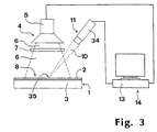
- FIG. 1 shows a schematic illustration of an exemplary embodiment of a device according to the invention for the photothermal examination of a test specimen 1, which is constructed from a substrate 3 provided with a thin coating 2.
- the coating 2 has a layer thickness which is formed by the distance between two interfaces of the coating 2.
- the device according to FIG. 1 has a lighting device 4, which has a flash lamp 5 as the lighting unit with an adjustable exposure time t P.
- the flash lamp 5 can be used to emit short, pulse-like light flashes with preferably intense spectral components in the visible spectral range, the exposure time t P being less than the propagation time of heat waves through the coating 2 to the interface adjacent to the test specimen 1.
- the light flashes act as exposure radiation 6 on the test specimen 1 after passing through an infrared filter 7 for absorbing infrared spectral components, essentially with their spectral components in the visible spectral range in an exposure area 8, which in this exemplary embodiment is extensive and strikes the coating 2.
- the energy of the exposure radiation 6 is dependent on the Absorption coefficients with a value preferably close to one absorbed in the exposure area 8, with some of the absorbed Energy again as heat radiation in the infrared spectral range is delivered.
- Part of the heat radiation 10 has the device according to FIG. 1 via a detection device 11 with a spatially resolving Infrared camera 12.
- the device according to FIG. 1 with a work station computer 13 designed control and evaluation device 14 equipped to which the flash lamp 5 and the infrared camera 12 are connected.
- FIG. 2 shows, in a block diagram, in particular the control and evaluation device 14 in the exemplary device according to FIG. 1.
- the control and evaluation device 14 has a control unit 15 to which the flash lamp 5 has a real-time image recording unit 16 connected to the infrared camera 12 a dynamic range of 12 bits and a time resolution of typically better a few milliseconds and a limit timer 17 are connected.
- the exposure time t P , an image recording time period as the end time t E and an efficiency evaluation time t A can be fed into the control unit 15 by means of the limit time value transmitter 17, the total duration of the recording of an emission curve being determined via the image recording time period and the point in time after the start of the exposure being determined with the efficiency evaluation time t A which defines the limit of the early cooling part of the emission curve immediately following a heating part for determining the effusiveness.
- the exposure time t P expediently corresponds to approximately half the time from the beginning of the exposure to the point in time of the effectiveness evaluation t A.
- the image recording time period For example, ten times the value that results from the quotient of the square of an estimated value for a layer thickness and an estimated value for a diffusivity of the coating 2 is provided as the image recording time period. It is advisable to choose half of this quotient as the time for evaluating the effectiveness t A.
- the output data of the real-time image acquisition unit 16 are one Image storage unit 18 can be fed, in which a number of images of the detection area 9 can be stored in a chronological sequence are, the number of storable images for one high temporal resolution is as high as possible. Appropriate number of pictures are between a few 10 to a few 1000 images a typical spatial resolution of, for example, 128 x 128 Pixels.
- An image processor unit is attached to the image storage unit 18 19 connected with which the of the detection area 9 emitted thermal radiation 10 associated data preferably for all pixels, but also for example for Image sections in the course of time as emission measurement curves are detectable.
- the emission measurement curves are an emission measurement curve memory 20 storable.
- control and evaluation device 14 has a model parameter memory 21, in which the thermal conductivity, the density, the specific heat capacity and the thickness of the substrate 3 of the test specimen 1 according to FIG. 1 as well as expediently an estimated value for parameters for calculating emission model curves the layer thickness of the coating 2 and an estimated value for the effusiveness of the coating 2 of the test specimen 1 can be stored.
- the model parameter memory 21 is connected to a short-term emission model curve computing unit 22.
- the short-term emission model curve computing unit 22 is connected to a heating energy measuring unit 23, with which a heating energy measurement parameter value associated with the exposure energy acting on the test specimen 1 can be generated.
- a number of emission model curves can be calculated when the model parameter for the effusivity is varied in the range of its estimated value in the time range up to the effusivity evaluation time t A stored in the limit time transmitter 17, including the heating energy measurement parameter value.
- the short-term emission model curves calculated with the short-term emission model curve computing unit 22 can be stored in a short-term emission model curve memory 24.
- the control and evaluation device 14 also has one Short-term emission curve comparison unit 25, which with the in the emission measurement memory 20 storable emission measurement curves and that in the short-term emission model curve memory 24 storable short-term emission model curves can be applied is.
- the short-term emission curve comparison unit 25 by means of a comparison procedure, for example using the method of the least squares in the time range up to the effusivity evaluation time those short-term emission model curves can be determined, those within the time range up to the time of the effectiveness evaluation with the emission measurement curves of the detected Pixels of the detection area 9 the best match in each case exhibit.
- the most adapted to the calculation of the Short-term emission model curves based on the effectiveness values are an effusivity image memory 26 as effusivity image of the detection area 9 can be stored.
- a derivation computing unit 27 is attached to the effusivity image memory 26 connected with the one from the value for the effusivity and one Value for diffusivity, for example according to the next
- the exemplary embodiment explained below with reference to FIG. 7 can be determined is, at one point of the coating 2, the thermal conductivity and the product of the density and the specific heat capacity at this point the coating 2 of the test specimen 1 can be determined are.
- the efficiency image memory 26 is attached to one Efficiency encoder 28 connected with which the minimum and the maximum of those stored in the efficiency image memory 26 Efficiency values can be determined and a number of preferably equally spaced intermediate effusivity values between the minimum efficiency value and can be calculated from the maximum efficiency value.
- the effusivity value generator 28 is connected to a long-term emission model curve computing unit 29, to which the model parameters of the model parameter storage unit 21 can also be fed.
- long-term emission model curve computing unit 29 long-term emission model curves can be calculated in the time range between the effectiveness evaluation time t A and the end time of the image recording time period with variation of the layer thickness in the range of their estimated values for each intermediate efficiency level, as well as the minimum and maximum efficiency values, which can be stored in one of the long-term emission model storage curve model long-term storage model 29.
- the memory content of the long-term emission model curve memory 30 can be output in a long-term emission curve comparison unit 31, which continue with the emission measurement curve memory 20 and an efficiency image converter 32 is connected.
- the Efficiency Imager 32 in turn is on the effusivity image memory 26 and the effusivity encoder 28 are connected. With the Efficiency imager 32 is the efficiency value on everyone Pixel of the detection area 9 that intermediate value or the minimum or maximum effectiveness value of the Efficiency generator 28 assignable to this efficiency value is closest to the pixel in question.
- the long-term emission curve comparison unit 31 is by means of a comparison procedure, for example according to the method of least squares for each pixel the layer thickness value determinable by means of which the best match can be found between the relevant emission measurement curve of this pixel and the corresponding long-term emission model curves on the Basis of the converted efficiency value from the efficiency image converter 32 results.
- the one with the long-term emission curve comparison unit 31 determined layer thickness values at the respective Pixels of the detection area 9 are in one Layer thickness image memory 33 can be stored.
- the memory contents of the effusivity image memory 26 and the Layer thickness image memories 33 are, for example, graphically in one Gray value or color coding via a not shown in Fig. 1 Output unit of the control and evaluation device 14, for example output in the form of a screen or printer.
- the exemplary device explained with reference to FIGS. 1 and 2 is particularly suitable for an essentially adjustment-free, spatially resolved, due to the comparison procedure of emission measurement curves with emission model curves in the short-term range up to the effusivity evaluation time t A, particularly precise determination of the effusiveness and by comparison of emission measurement curves and emission model curves in Long-term range between the time of the effectiveness evaluation and the end of the image acquisition period for a very exact, spatially resolved determination of the layer thickness of the coating 2 of the test specimen 1.
- FIG. 3 shows a further exemplary embodiment in a schematic illustration a device for photothermal examination of a test specimen 1 which, apart from the detection device 11 similar to the embodiment explained with reference to FIG. 1 is constructed. Accordingly, they are in the embodiments 1 and FIG. 3 corresponding components provided with the same reference numerals and in the rest not explained in more detail.
- the detection device 11 in the 3 is a single-cell infrared point detector 34 formed with the heat radiation 10 from a within the exposure area 8, very small, compared to the exposure area 8 quasi-point-shaped detection area 35 can be recorded in a time-resolved manner.
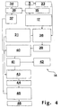
- FIG. 4 shows in a block diagram the device according to FIG. 3, 2 and 4, corresponding components are provided with the same reference numerals in the embodiments of the control and evaluation devices 14 and are not explained in more detail below.
- the infrared point detector 34 is connected to a measurement signal converter 36 connected, which in turn is controlled by the control unit 15 is.
- the point-shaped by means of the infrared point detector 34 Detection area 35 is detected thermal radiation 10 time-resolved as a single emission measurement curve in one to the measurement signal converter 36 connected single emission trace memories 37 can be saved.
- the model parameter memory 21 is connected to a short-term emission model value computing unit 38, which in turn is connected to the limit time transmitter 17 and the heating energy measuring unit 23.
- the temperatures prevailing at this determination time t B can be calculated as emission model values, depending on the effusiveness, at a determination time t B , taking into account the heating energy acting on the test specimen 1 and the model parameters from the model parameter memory 21 with variation of the effusivity in the range of the effusivity estimate the time of determination t B is less than the time of effectiveness evaluation t A.
- the point in time t B is approximately half the time which has elapsed from the beginning of the exposure of the test specimen 1 to the point in time of the effusivity evaluation t A.
- the short-term emission model value computing unit 38 is followed by a short-term emission model value memory 39, in which the emission model values calculated at the determination point in time t B can be stored.
- the control and evaluation device 14 according to FIG. 4 furthermore has a short-term emission value comparison unit 40 connected to the short-term emission model value memory 39 and the single emission measurement curve memory 37, with which, in accordance with the mode of operation of the short-term emission curve comparison unit 25 according to FIG. 2, the emission model value with the least deviation from the emission measurement value of the single emission measurement curve
- a single efficiency model value can be determined for the detection area 35 and can be stored in an individual efficiency value memory 41.
- the single efficiency value of the single efficiency value memory 41 is a single derivation computing unit 42 for calculating the thermal conductivity and the product of the density and the specific Heat capacity according to the functioning of the discharge computing unit 27 feedable.
- the Einzeleffus citizenshipswert official 41 and the model parameter memory 21 is followed by a long-term emission model curve computing unit 43, with the at variation of the layer thickness of the coating 2 in the region whose estimation value and the data stored in the Einzeleffus Kunststoffswert agenda 41 Effus beautiesswert long-term emission model curves in a time domain between the effusivity t A and the end time t E of the measurement period are predictable.
- the long-term emission model curves calculated by means of the long-term emission model curve computing unit 43 can be fed into a long-term emission model curve memory 44, which is followed by a long-term emission curve comparison unit 45.
- the layer thickness of the coating 2 at the relevant pixel is based on the best match in a comparison procedure, for example according to the least squares method within the time range between the effectiveness evaluation time t A and the end time t E of the measurement duration
- Long-term emission model curve can be determined with the emission measurement curve in the corresponding time range.
- the layer thickness value determined by means of the long-term emission curve comparison unit 45 can be stored in a downstream layer thickness value memory 46 and can be output, for example, via a screen (not shown in FIG. 4) or a printer of the control and evaluation device 14.
- the exemplary embodiment according to FIGS. 3 and 4 is in particular then usable if a particularly fast Determination of the effusivity and the layer thickness in a punctiform Detection area 35 should take place.
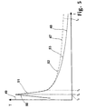
- FIG. 5 shows in a diagram an example of a first emission model curve 47 and a second emission model curve 48, as can be seen in a partial area of the detection area 9 or in a point-shaped detection area 35 after exposure to short light flashes 49 from the illumination unit designed as a flash lamp 5 according to numerical model calculations result.
- the time course of the amplitude of the emission model curves 47, 48 is plotted in this representation as temperature "T" along a time axis "t”.
- the exposure time t P of the flash of light 49 is equal to the heating-up time of the heating part 50 of both emission model curves 47, 48 rising up to a maximum temperature.
- the heating part is also 50 can be used to determine effusivity.
- the layer thickness of the coating is then compared with the course of the cooling parts 52, 53 of the emission model curves 47, 48 by comparison with the emission measurement curve 2 of the test specimen 1 can be precisely determined.
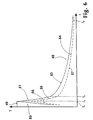
- FIG. 6 shows the second emission model curve in a graph 48 in accordance with FIG. 5 in comparison with a third emission model curve 54
- the emission model curves shown in FIG. 6 48, 54 each have a test specimen 1 with the same substrate 3 and the same layer thickness of a coating 2 from different ones Materials. Because of the different Materials of the coatings 2 and the rule different associated effusivities is a heating part 55, a section directly adjoining the heating part 55 56 and the rest of the course of a cooling part 57 of third emission model curve 54 from the course of the second Emission model curve 48 different. This allows different Materials of a coating 2 of a test specimen 1 determine their different effusivities.
- the device 7 shows a further exemplary embodiment in a schematic illustration a device for photothermal examination a test specimen 58 made of a with a coating 59 provided substrate 60 is constructed.
- the device 7 has a lighting device 61, the as a radiation source over a preferably in the visible spectral range has continuously emitting laser 62.
- the Laser 62 is a shutter unit 63 and a focusing lens 64 subordinate, with the closure unit 63 open from exposure radiation 65 emitted by laser 62 in a punctiform manner Exposure area 66 on the coating 59 of the Test body 58 is focusable.
- the device according to FIG. 7 has a detection device 67 with a single-cell infrared point detector 68.
- the infrared point detector 68 is with a point-like detection area 69 at a center distance indicated by an arrow r as the distance from the punctiform exposure area 66 for detection of those emitted from the detection region 69 Heat radiation 70 aligned.
- a Workstation computer 71 designed control and evaluation device 72 equipped to which the laser 62, the shutter unit 63 and the infrared point detector 68 for controlling the Exposure and detection of heat radiation 70 and for Evaluation are connected.
- FIG. 8 shows the device according to FIG. 7 in a block diagram especially with the construction of the control and evaluation device 72.
- the control and evaluation device 72 has one Control unit 73 to control an exposure time from an exposure timer 74 at least two exposure times assigned control data can be fed. For example a shorter first exposure time corresponds to a quarter of the Quotient from the square of an estimated value for a Layer thickness of the coating 59 and an estimate for a Diffusivity of the coating 59 and a longer second exposure time half of this quotient. With those from the exposure timer 74 shutter speeds is the shutter unit 63 can be actuated accordingly. Furthermore, the laser 62 connected to the control unit 73 for function monitoring.
- the infrared point detector 68 is for digitized data acquisition a measurement signal converter 75 downstream, the clocked Signal conversion is also connected to the control unit 73 is.
- the output data assigned to each exposure time of the measurement signal converter 75, the time course typically by an associated temperature value characterized intensity of the heat radiation 70 from the in a diffusion distance r from the exposure area 66 Detection area 69 correspond to are emission measurement curves can be stored in an emission measurement memory 76.
- Emission measurement curves are at an emission maximum search unit 77 transferable, by means of which the for each emission measurement curve Maximum of the maximum temperature associated with the emission Start of exposure and via direct evaluation of the emission measurement curve or alternatively by entering an exposure time the time of the maximum emission can be determined.
- the Control and evaluation device 72 also has a Diffusivity arithmetic unit 78, on the one hand with the emission maximum search unit 77 and on the other hand with a model parameter memory 79 is connected.
- the model parameter memory 79 are the center distance r between the punctiform Exposure area 66 and the point-shaped detection area 69 and an estimate for the diffusivity can be stored.
- the diffusivity computing unit 78 is with a numerical Methods, for example the Newton method Variation of the estimated value of the diffusivity in the above Equation (2) determines the diffusivity of the coating 59.
- the control and evaluation device 72 also has a derivation arithmetic unit 80 which is connected to the diffusion arithmetic unit 78 is connected.
- the derivation computing unit 80 By means of the derivation computing unit 80 the determined diffusivity and, for example, by means of one of the aforementioned devices according to Fig. 1 and Fig. 2 and FIGS. 3 and 4 ascertained effusivity the thermal conductivity as well as the product of the density and the specific heat capacity the coating 59 can be determined.
- the detection device 67 according to FIG. 7 also with an infrared line-scan camera or a surface detector Infrared camera can be equipped.
Description
Die Erfindung betrifft Verfahren zum photothermischen Untersuchen eines Prüfkörpers, bei dem der Prüfkörper in einem Belichtungsbereich mit Belichtungsstrahlung während einer Belichtungsdauer beaufschlagt und von dem Prüfkörper aus einem Erfassungsbereich abgegebene Wärmestrahlung zeitaufgelöst erfaßt wird, wobei aus dem zeitlichen Verlauf der durch eine Emissionskurve mit einem Aufheizteil mit zunehmender Amplitude und einem Abkühlteil mit abnehmender Amplitude repräsentierbaren Wärmestrahlung Eigenschaften des Prüfkörpers bestimmt werden.The invention relates to methods for photothermal examination a test specimen in which the test specimen is in an exposure area with exposure radiation during an exposure period acted upon and by the test specimen from a detection area emitted heat radiation recorded time-resolved is, from the time course of an emission curve with a heating part with increasing amplitude and a cooling part with decreasing amplitude representable Thermal radiation properties of the test specimen can be determined.
Die Erfindung betrifft weiterhin Vorrichtungen zum photothermischen Untersuchen eines Prüfkörpers, mit einer Beleuchtungseinrichtung, mit der ein Prüfkörper in einem Belichtungsbereich mit Belichtungsstrahlung während einer Belichtungsdauer beaufschlagbar ist, mit einer Detektionseinrichtung, mit der von dem Prüfkörper aus einem Erfassungsbereich abgegebene Wärmestrahlung zeitaufgelöst erfaßbar ist, und mit einer Steuer- und Auswerteeinrichtung, mit der aus dem zeitlichen Verlauf der durch eine Emissionskurve mit einem Aufheizteil mit zunehmender Amplitude und einem Abkühlteil mit abnehmender Amplitude repräsentierbaren Wärmestrahlung Eigenschaften des Prüfkörpers bestimmbar sind.The invention further relates to devices for photothermal Examination of a test specimen with a lighting device, with a test specimen in an exposure area Exposure radiation can be applied during an exposure period is, with a detection device with the test specimen thermal radiation emitted from a detection area is time-resolved, and with a control and evaluation device, with the from the time course of an emission curve with a heating part with increasing amplitude and a cooling part with decreasing amplitude representable Thermal radiation properties of the test specimen can be determined.
Derartige Verfahren und Vorrichtungen sind aus der DE 38 20 862 A1 bekannt. Ein Prüfkörper ist mittels einer Beleuchtungseinrichtung mit Belichtungsstrahlung in einem Belichtungsbereich während einer Belichtungsdauer beaufschlagt. Zum zeitaufgelösten Erfassen von von dem Prüfkörper aus einem Erfassungsbereich abgegebener Wärmestrahlung dient eine Detektionseinrichtung. Die erfaßte Wärmestrahlung ist bei Abtragung einer Temperatur gegen die Zeit durch eine Emissionskurve mit einem Aufheizteil mit zunehmender Amplitude und mit einem Abkühlteil mit abnehmender Amplitude repräsentierbar, wobei aus zeitlichen Korrelationen zwischen der Beaufschlagung des Prüfkörpers mit Belichtungsstrahlung und dem Verlauf der Emissionskurve Eigenschaften des Prüfkörpers bestimmt werden. Bei den gattungsgemäßen Verfahren und Vorrichtungen werden zum Erfassen von Fehlerstellen Abweichungen von Emissionsmeßkurven gegenüber anhand von Vorgabeparametern wie Wärmeleitfähigkeit, Absorptions- und/oder Emissionskoeffizient berechneten Emissionsmodellkurven bestimmt.Such methods and devices are from DE 38 20 862 A1 known. A test specimen is by means of a lighting device with exposure radiation in an exposure area applied during an exposure period. For time-resolved Detection of the test specimen from a detection area emitted heat radiation is used by a detection device. The heat radiation detected is one when removed Temperature versus time through an emission curve with a Heating section with increasing amplitude and with a cooling section representable with decreasing amplitude, whereby from temporal Correlations between loading the test specimen with Exposure radiation and the course of the emission curve properties of the test specimen can be determined. In the generic Methods and devices are used to detect Defects versus deviations from emission measurement curves based on default parameters such as thermal conductivity, absorption and / or emission coefficient calculated emission model curves certainly.
Aus der US-A-4,679,946 sind ein Verfahren und eine Vorrichtung zum Bestimmen sowohl einer Schichtdicke als auch von Materialparametern eines schichtartig aufgebauten Prüfkörpers bekannt, bei denen der Prüfkörper mit Belichtungsstrahlung beaufschlagt und von ihm abgegebene Wärmestrahlung erfaßt wird. Hierzu werden zwei voneinander unabhängig arbeitende Meßverfahren verwendet, wobei zum einen einer Oberflächentemperatur zugeordnete thermische Signale und zum anderen einer hauptsächlich als Funktion der Temperatur unterhalb der Oberfläche vorliegende Signale erfaßt und verarbeitet werden. Durch die Verwendung eines zweisegmentigen Detektors sind diese beiden Signaltypen zugleich unabhängig voneinander erfaßbar. Allerdings werden bei dieser Vorrichtung zwei als Laser ausgebildete Strahlungsquellen sowie das speziell ausgeführte Detektorelement benötigt.US-A-4,679,946 discloses a method and an apparatus for determining both a layer thickness and material parameters of a layered test specimen known, where the test specimen is exposed to exposure radiation and heat radiation emitted by it is detected. For this become two independent measuring methods used, on the one hand associated with a surface temperature thermal signals and the other one mainly as a function of the temperature below the surface Signals are recorded and processed. By using it these are two of a two-segment detector Signal types can be detected independently of one another at the same time. Indeed are two radiation sources designed as lasers in this device as well as the specially designed detector element needed.
Der Erfindung liegt die Aufgabe zugrunde, Verfahren und Vorrichtungen der eingangs genannten Art anzugeben, mit denen in apparativ wenig aufwendiger Weise Materialeigenschaften des Prüfkörpers auch bei Unkenntnis exakter Schichtdicken verhältnismäßig genau bestimmt werden können.The invention has for its object methods and devices of the type mentioned at the beginning, with which in less expensive in terms of equipment material properties of the The test specimen is proportionate even if the exact layer thickness is not known can be determined exactly.
Diese Aufgabe wird bei dem eingangs genannten Verfahren in einer Ausgestaltung eines ersten Typs dadurch gelöst, daß eine impulsartige Belichtungsdauer eingestellt wird, die kleiner als der Quotient aus dem Quadrat eines Schätzwertes einer durch den Abstand von Grenzflächen gebildeten Schichtdicke und eines Schätzwertes für die Diffusivität zwischen den Grenzflächen ist, und daß aus wenigstens einem in dem Aufheizteil oder einem sich unmittelbar an den Aufheizteil anschließenden Abschnitt des Abkühlteiles mit einer hohen, einer Aufheizrate des Aufheizteiles entsprechenden Abkühlrate gelegenen Meßwert die Effusivität des Prüfkörpers bestimmt wird.This task is performed in the method mentioned in an embodiment of a first type in that a pulse-like exposure time is set, which is smaller than that Quotient from the square of an estimate of one by the Distance between interfaces and a layer thickness Is an estimate of the diffusivity between the interfaces, and that of at least one in the heating part or one itself directly adjacent to the heating section of the Cooling section with a high heating rate of the heating section according to the corresponding cooling rate, the effusivity of the Specimen is determined.
Diese Aufgabe wird bei der eingangs genannten Vorrichtung in einer Ausgestaltung eines ersten Typs dadurch gelöst, daß mit der Beleuchtungseinrichtung wenigstens eine Belichtungsdauer einstellbar ist, die kleiner als der Quotient aus dem Quadrat eines Schätzwertes einer durch den Abstand von Grenzflächen gebildeten Schichtdicke und eines Schätzwertes für die Diffusivität zwischen den Grenzflächen ist, und daß eine Recheneinheit vorgesehen ist, mit der aus wenigstens einem in dem Aufheizteil oder einem sich unmittelbar an den Aufheizteil anschließenden Abschnitt des Abkühlteiles mit einer hohen, einer Aufheizrate des Aufheizteiles entsprechenden Abkühlrate gelegenen Meßwert die Effusivität des Prüfkörpers bestimmbar ist.This task is in the device mentioned in an embodiment of a first type solved in that with the Illumination device adjustable at least one exposure duration is less than the quotient of the square of one Estimated value of one formed by the distance between interfaces Layer thickness and an estimate for the diffusivity between the interfaces, and that a computing unit is provided with which at least one in the heating part or a section immediately adjacent to the heating part of the cooling section with a high heating rate of Heating part corresponding cooling rate located the measured value Efficiency of the test specimen can be determined.
Dadurch, daß bei dem Verfahren und der Vorrichtung des ersten Typs wenigstens ein Meßwert innerhalb des sehr kurzen Aufheizteiles oder in dem sich unmittelbar an das Ende der impulsartigen Belichtung anschließenden Teilabschnitt der Emissionskurve nach einer der Erfindung zugrundeliegenden Erkenntnis, daß bei impulsartiger Belichtung in diesem Bereich der Emissionskurve der Einfluß der Schichtdicke auf die Messung von Materialeigenschaften vernachlässigbar ist, erfaßt wird, lassen sich Materialeigenschaften auch bei Unkenntnis der Schichtdicke sehr genau aus wenigstens einem Meßwert bestimmen.The fact that in the method and apparatus of the first Type at least one measured value within the very short heating section or in which immediately at the end of the impulse-like Exposure subsequent portion of the emission curve after one of the findings on which the invention is based, that with pulse-like Exposure in this area of the emission curve Influence of the layer thickness on the measurement of material properties is negligible, is detected, material properties even if the layer thickness is unknown determine at least one measured value.
Diese Aufgabe wird weiterhin bei dem eingangs genannten Verfahren in einer Ausgestaltung eines zweiten Typs dadurch gelöst, daß wenigstens zwei Belichtungsdauern eingestellt werden, die kleiner als der Quotient aus dem Quadrat eines Schätzwertes für eine Schichtdichte der Beschichtung und eines Schätzwertes für die Diffusivität der Beschichtung sind, daß der Belichtungsbereich und der Erfassungsbereich mit einem Diffusionsabstand voneinander beabstandet werden, daß die sich für jede Belichtungsdauer im Erfassungsbereich einstellenden Maximalamplituden jeder Emissionskurve mit zugehörigen Einstellzeiten bestimmt werden und daß aus dem Verhältnis wenigstens zweier Maximalamplituden, dem Diffusionsabstand und den zugehörigen Einstellzeiten die Diffusivität bestimmt wird.This task continues with the procedure mentioned at the beginning solved in an embodiment of a second type, that at least two exposure times are set, the less than the quotient of the square of an estimate for a layer density of the coating and an estimate for the diffusivity of the coating is that of the exposure area and the detection area with a diffusion distance from each other be spaced apart for each exposure duration maximum amplitudes of each emission curve that set in the detection range can be determined with associated response times and that from the ratio of at least two maximum amplitudes, the diffusion distance and the associated response times Diffusivity is determined.
Diese Aufgabe wird bei der eingangs genannten Vorrichtung in einer Ausgestaltung eines zweiten Typs dadurch gelöst, daß mit der Beleuchtungseinrichtung wenigstens zwei Belichtungsdauern einstellbar sind, die kleiner als der Quotient aus dem Quadrat eines Schätzwertes einer durch den Abstand von Grenzflächen gebildeten Schichtdicke und eines Schätzwertes für die Diffusivität zwischen den Grenzflächen ist, daß der Belichtungsbereich und der Erfassungsbereich mit einem Diffussionsabstand voneinander beabstandet sind, daß mit einer Emissionsmaximumssucheinheit sich für jede Belichtungsdauer im Erfassungsbereich einstellenden Maximalamplituden jeder Emissionskurve mit zugehörigen Einstellzeiten bestimmbar sind und daß mit einer Diffusivitätsrecheneinheit aus dem Verhältnis zweier Maximalamplituden, dem Diffusionsabstand und den zugehörigen Einstellzeiten eine Diffusivität bestimmbar ist.This task is in the device mentioned in an embodiment of a second type in that with the lighting device at least two exposure times are adjustable that are smaller than the quotient of the square an estimate of one by the distance from interfaces formed layer thickness and an estimate for the diffusivity between the interfaces is that the exposure area and the detection area with a diffusion distance from each other are spaced that with an emission maximum search unit occurring in the detection range for each exposure duration Maximum amplitudes of each emission curve with associated response times can be determined and that with a diffusivity computing unit from the ratio of two maximum amplitudes, the diffusion distance and the associated response times a diffusivity is determinable.
Dadurch, daß bei dem Verfahren und der Vorrichtung des zweiten Typs nach einer verhältnismäßig kurzen, impulsartigen Aufheizung die Ausbreitung der Wärmewellen über die Maximalamplituden von Emissionskurven nach unterschiedlich langer Belichtung erfaßt wird, läßt sich die Diffusivität bei Kenntnis des Diffusionsabstandes unabhängig von der Leistungsdichte der Belichtungsstrahlung bestimmen. The fact that in the method and the device of the second Type after a relatively short, pulse-like heating the propagation of the heat waves over the maximum amplitudes of emission curves after exposure of different lengths the diffusivity can be known by knowing the diffusion distance regardless of the power density of the exposure radiation determine.
In zweckmäßigen Weiterbildungen des Verfahrens und der Vorrichtung des ersten Typs wird nach ermittelter Effusivität auch die Schichtdicke bestimmt, die aus dem Langzeitverlauf der Emissionkurve ermittelbar ist.In practical developments of the method and the device of the first type is also the Layer thickness determined from the long-term course of the emission curve can be determined.
Zur Steigerung der Meßgenauigkeit der Effusivität ist in Weiterbildungen des Verfahrens und der Vorrichtung des ersten Typs vorgesehen, in dem Aufheizteil oder in dem sich unmittelbar an den Aufheizteil anschließenden Abkühlteil der Emissionskurve eine Anzahl von Emissionsmeßwerten zu erfassen und mit der Vorgabe von anhand Modellparametern berechneten Emissionsmodellkurven zu vergleichen, wobei aus der Emissionsmodellkurve mit den geringsten Abweichungen gegenüber den Meßwerten die Materialeigenschaften ableitbar sind.To increase the measuring accuracy of the effusivity is in further training of the method and the device of the first type provided in the heating part or in which immediately the heating part, the cooling part of the emission curve Number of emission measurements to be recorded and with the specification emission model curves calculated on the basis of model parameters to compare, taking from the emission model curve with the smallest deviations from the measured values Material properties can be derived.
Bei zweckmäßigen Weiterbildungen des Verfahrens und der Vorrichtung des zweiten Typs sind zwei Belichtungen mit vorzugsweise um einen Faktor zwei verschiedenen Belichtungsdauern vorgesehen, wobei die längere Belichtungsdauer der Hälfte des Quotienten aus dem Quadrat des Schätzwertes für eine Schichtdicke einer Beschichtung und dem Schätzwert für die Diffusivität der Beschichtung ist. Dadurch ist sichergestellt, daß der Einfluß der Schichtdicke vernachlässigbar ist.In the case of expedient further developments of the method and the device of the second type, two exposures are preferred by a factor of two different exposure times, the longer exposure time of half the Quotients from the square of the estimate for a layer thickness a coating and the estimated value for the diffusivity the coating is. This ensures that the influence the layer thickness is negligible.
Zur Erläuterung der physikalischen Zusammenhänge bei dem Verfahren und der Vorrichtung des ersten Typs seien nachfolgend einige Bestimmungsgleichungen angegeben.To explain the physical relationships in the The method and the device of the first type are as follows some equations of determination given.
Die Effusivität ist die Wurzel aus dem Produkt der Wärmeleitfähigkeit, der Dichte und der spezifischen Wärmekapazität. Unter Diffusivität versteht man den Quotient aus der Wärmeleitfähigkeit und der mit der Dichte multiplizierten spezifischen Wärmekapazität. The effusiveness is the root of the product of the thermal conductivity, density and specific heat capacity. Under Diffusivity is understood to be the quotient of thermal conductivity and the specific heat capacity multiplied by density.
Aus der instationären Wärmeleitungstheorie ergibt sich beispielsweise
folgender, eine Emissionskurve repräsentierender Temperaturverlauf
an der Oberfläche eines Prüfkörpers für den Aufheizteil
und den frühen Abkühlteil nach Ende der Belichtung mit einem
kurzen Rechteckimpuls:

Bei dem Verfahren und der Vorrichtung des zweiten Typs liegt der
Bestimmung der Diffusivität folgende Gleichung zugrunde:

Weitere zweckmäßige Ausgestaltungen und Vorteile der Erfindung sind Gegenstand der Unteransprüche sowie der nachfolgenden Beschreibung von Ausführungsbeispielen mit Bezug auf die Figuren der Zeichnung. Es zeigen:
- Fig. 1
- in einer schematischen Darstellung ein Ausführungsbeispiel einer erfindungsgemäßen Vorrichtung beim Untersuchen eines Prüfkörpers mit einer eine Infrarotkamera aufweisenden Detektionseinrichtung,
- Fig. 2
- in einem Blockschaltbild die Vorrichtung gemäß Fig. 1,
- Fig. 3
- ein weiteres Ausführungsbeispiel einer erfindungsgemäßen Vorrichtung mit einer einen einzelligen Infrarotdetektor aufweisenden Detektionseinrichtung,
- Fig. 4
- in einem Blockschaltbild die Vorrichtung gemäß Fig. 3,
- Fig. 5
- Emissionskurven von Prüfkörpern mit Beschichtungen gleicher Materialzusammensetzung, jedoch unterschiedlicher Schichtdicke,
- Fig. 6
- Emissionskurven von Prüfkörpern mit Beschichtungen unterschiedlicher Materialzusammensetzungen, jedoch gleicher Schichtdicke,
- Fig. 7
- in einer schematischen Darstellung ein weiteres Ausführungsbeispiel einer Vorrichtung zum photothermischen Untersuchen eines Prüfkörpers mit einer in einem punktförmigen Belichtungsbereich fokussierenden Beleuchtungseinrichtung und einer Detektionseinrichtung mit einem punktförmigen, von dem Belichtungsbereich beabstandeten Erfassungsbereich beim Untersuchen eines Prüfkörpers und
- Fig. 8
- in einem Blockschaltbild die Vorrichtung gemäß Fig. 7.
- Fig. 1
- a schematic representation of an embodiment of a device according to the invention when examining a test specimen with a detection device having an infrared camera,
- Fig. 2
- 1 in a block diagram,
- Fig. 3
- 1 a further exemplary embodiment of a device according to the invention with a detection device having a single-cell infrared detector,
- Fig. 4
- 3 shows a block diagram of the device according to FIG.
- Fig. 5
- Emission curves of test specimens with coatings of the same material composition but different layer thickness,
- Fig. 6
- Emission curves of test specimens with coatings of different material compositions, but the same layer thickness,
- Fig. 7
- In a schematic representation, a further exemplary embodiment of a device for the photothermal examination of a test specimen with an illuminating device focusing in a punctiform exposure area and a detection device with a punctiform detection area spaced from the exposure area when examining a test specimen and
- Fig. 8
- 7 shows the device according to FIG. 7 in a block diagram.
Fig. 1 zeigt in einer schematischen Darstellung ein Ausführungsbeispiel
einer erfindungsgemäßen Vorrichtung zum photothermischen
Untersuchen eines Prüfkörpers 1, der aus einem mit einer
dünnen Beschichtung 2 versehenen Substrat 3 aufgebaut ist. Die
Beschichtung 2 weist eine Schichtdicke auf, die durch den Abstand
von zwei Grenzflächen der Beschichtung 2 gebildet ist. Die
Vorrichtung gemäß Fig. 1 verfügt über eine Beleuchtungseinrichtung
4, die als Beleuchtungseinheit mit einer einstellbaren Belichtungsdauer
tP eine Blitzlampe 5 aufweist. Mit der Blitzlampe 5 sind
kurze, impulsartige Lichtblitze mit vorzugsweise intensiven Spektralkomponenten
im sichtbaren Spektralbereich emittierbar, wobei
die Belichtungsdauer tP kleiner als die Laufzeit von Wärmewellen
durch die Beschichtung 2 zu der dem Prüfkörper 1 benachbarten
Grenzfläche ist. Diese entspricht dem Quotienten aus dem Quadrat
eines Wertes einer durch den Abstand von Grenzflächen
gebildeten Schichtdicke der Beschichtung 2 und eines Wertes für
die Diffusivität zwischen den Grenzflächen. Die Lichtblitze beaufschlagen
als Belichtungsstrahlung 6 den Prüfkörper 1 nach Durchgang
durch ein Infrarotfilter 7 zum Absorbieren von infraroten
Spektralanteilen im wesentlichen mit ihren Spektralkomponenten
im sichtbaren Spektralbereich in einem in diesem Ausführungsbeispiel
flächenhaft ausgedehnten Belichtungsbereich 8 unter Auftreffen
auf die Beschichtung 2. 1 shows a schematic illustration of an exemplary embodiment of a device according to the invention for the photothermal examination of a
Die Energie der Belichtungstrahlung 6 wird in Abhängigkeit des
Absorptionskoeffizienten mit einem Wert vorzugsweise nahe eins
im Belichtungsbereich 8 absorbiert, wobei ein Teil der absorbierten
Energie wieder als Wärmestrahlung im infraroten Spektralbereich
abgegeben wird. Zum Erfassen von aus einem innerhalb des
Belichtungsbereiches 8 in einem Erfassungsbereich 9 gelegenen
Teiles der Wärmestrahlung 10 verfügt die Vorrichtung gemäß Fig.
1 über eine Detektionseinrichtung 11 mit einer ortsauflösenden
Infrarotkamera 12.The energy of the
Weiterhin ist die Vorrichtung gemäß Fig. 1 mit einer als Arbeitsplatzrechner
13 ausgestalteten Steuer- und Auswerteeinrichtung
14 ausgestattet, an die die Blitzlampe 5 und die Infrarotkamera 12
angeschlossen sind.Furthermore, the device according to FIG. 1 with a
Fig. 2 zeigt in einem Blockschaltbild insbesondere die Steuer- und
Auswerteeinrichtung 14 bei der beispielhaften Vorrichtung gemäß
Fig. 1. Die Steuer- und Auswerteeinrichtung 14 verfügt über eine
Steuereinheit 15, an die die Blitzlampe 5, eine mit der Infrarotkamera
12 verbundene Echtzeitbildaufnahmeeinheit 16 mit einer
Dynamik von 12 Bit und einer Zeitauflösung von typischerweise
besser einigen Millisekunden sowie ein Grenzzeitwertgeber 17
angeschlossen sind. Mittels des Grenzzeitwertgebers 17 sind der
Steuereinheit 15 die Belichtungsdauer tP, eine Bildaufnahmezeitdauer
als Endzeitpunkt tE und ein Effusivitätsauswertezeitpunkt tA
einspeisbar, wobei über die Bildaufnahmezeitdauer die Gesamtdauer
der Aufnahme einer Emissionskurve und mit dem Effusivitätsauswertezeitpunkt
tA der Zeitpunkt nach dem Beginn der
Belichtung festgelegt wird, der die Grenze der sich unmittelbar an
einen Aufheizteil anschließenden frühen Abkühlteil der Emmissionskurve
zum Bestimmen der Effusivität festlegt. Die Belichtungsdauer
tP entspricht zweckmäßigerweise etwa der Hälfte der
Zeit von dem Beginn der Belichtung bis zu dem Effusivitätsauswertezeitpunkt
tA. Als Bildaufnahmezeitdauer ist beispielsweise
das Zehnfache des Wertes vorgesehen, der sich aus dem Quotienten
des Quadrates eines Schätzwertes für eine Schichtdicke und
einem Schätzwert für eine Diffusivität der Beschichtung 2 ergibt.
Als Effusivitätsauswertezeitpunkt tA ist es zweckmäßig, die Hälfte
dieses Quotienten zu wählen.FIG. 2 shows, in a block diagram, in particular the control and
Die Ausgangsdaten der Echtzeitbildaufnahmeeinheit 16 sind einer
Bildspeichereinheit 18 einspeisbar, in der eine Anzahl von Bildern
des Erfassungsbereiches 9 in einer zeitlichen Abfolge abspeicherbar
sind, wobei die Anzahl der abspeicherbaren Bilder für eine
hohe zeitliche Auflösung möglichst hoch ist. Zweckmäßige Bilderanzahlen
liegen zwischen einigen 10 bis wenigen 1000 Bildern bei
einer typischen Ortsauflösung von beispielsweise 128 x 128
Bildpunkten. An die Bildspeichereinheit 18 ist eine Bildprozessoreinheit
19 angeschlossen, mit der die der aus dem Erfassungsbereich
9 abgegebenen Wärmestrahlung 10 zugeordneten Daten
vorzugsweise für alle Bildpunkte, aber beispielsweise auch für
Bildausschnitte in dem zeitlichen Verlauf als Emissionsmeßkurven
erfaßbar sind. Die Emissionsmeßkurven sind einem Emissionsmeßkurvenspeicher
20 einspeicherbar.The output data of the real-time
Weiterhin weist die Steuer- und Auswerteeinrichtung 14 einen
Modellparameterspeicher 21 auf, in dem als Parameter für eine
Berechnung von Emissionsmodellkurven die Wärmeleitfähigkeit,
die Dichte, die spezifische Wärmekapazität sowie die Dicke des
Substrates 3 des Prüfkörpers 1 gemäß Fig. 1 sowie zweckmäßigerweise
weiterhin ein Schätzwert für die Schichtdicke der
Beschichtung 2 und ein Schätzwert für die Effusivität der Beschichtung
2 des Prüfkörpers 1 abspeicherbar sind. Der Modellparameterspeicher
21 ist an eine Kurzzeitemissionsmodellkurvenrecheneinheit
22 angeschlossen. Die Kurzzeitemissionsmodellkurvenrecheneinheit
22 steht mit einer Heizenergiemeßeinheit 23
in Verbindung, mit der ein der den Prüfkörper 1 beaufschlagenden
Belichtungsenergie zugeordneter Heizenergiemeßparameterwert
erzeugbar ist. Mit der Kurzzeitemissionsmodellkurvenrecheneinheit
22 ist bei Variation des Modellparameters für die Effusivität im
Bereich deren Schätzwertes im Zeitbereich bis zu dem in dem
Grenzzeitwertgeber 17 abgelegten Effusivitätsauswertezeitpunkt
tA unter Einschluß des Heizenergiemeßparameterwertes eine
Anzahl von Emissionsmodellkurven berechenbar. Die mit der
Kurzzeitemissionsmodellkurvenrecheneinheit 22 berechneten
Kurzzeitemissionsmodellkurven sind einem Kurzzeitemissionsmodellkurvenspeicher
24 einspeicherbar.Furthermore, the control and
Die Steuer- und Auswerteeinrichtung 14 weist weiterhin eine
Kurzzeitemissionskurvenvergleichseinheit 25 auf, die mit den in
den Emissionsmeßspeicher 20 abspeicherbaren Emissionsmeßkurven
und den in dem Kurzzeitemissionsmodellkurvenspeicher 24
abspeicherbaren Kurzzeitemissionsmodellkurven beaufschlagbar
ist. Mit der Kurzzeitemissionskurvenvergleichseinheit 25 sind
mittels einer Vergleichsprozedur beispielsweise nach der Methode
der kleinsten Quadrate in dem Zeitbereich bis zu dem Effusivitätsauswertezeitpunkt
diejenigen Kurzzeitemissionsmodellkurven bestimmbar,
die innerhalb des Zeitbereiches bis zu dem Effusivitätsauswertezeitpunkt
mit den Emissionsmeßkurven der erfaßten
Bildpunkte des Erfassungsbereiches 9 die jeweils beste Übereinstimmung
aufweisen. Die der Berechnung der am besten angepaßten
Kurzzeitemissionsmodellkurven zugrundeliegenden Effusivitätswerte
sind einem Effusivitätsbildspeicher 26 als Effusivitätsbild
des Erfassungsbereiches 9 einspeicherbar.The control and
An den Effusivitätsbildspeicher 26 ist eine Ableitrecheneinheit 27
angeschlossen, mit der aus dem Wert für die Effusivität und einem
Wert für die Diffusivität, der beispielsweise gemäß dem weiter
unten anhand Fig. 7 erläuterten Ausführungsbeispiel ermittelbar
ist, an einem Punkt der Beschichtung 2 die Wärmeleitfähigkeit und
das Produkt aus der Dichte und der spezifischen Wärmekapazität
an diesem Punkt der Beschichtung 2 des Prüfkörpers 1 bestimmbar
sind. Weiterhin ist der Effusivitätsbildspeicher 26 an einen
Effusivitätswertgeber 28 angeschlossen, mit dem das Minimum
und das Maximum der in dem Effusivitätsbildspeicher 26 abgespeicherten
Effusivitätswerte bestimmbar ist und eine Anzahl von
vorzugsweise einen gleichen Abstand aufweisenden Effusivitätszwischenwerten
zwischen dem minimalen Effusivitätswert und
dem maximalen Effusivitätswert berechenbar sind.A
Der Effusivitätswertgeber 28 ist an eine Langzeitemissionsmodellkurvenrecheneinheit
29 angeschlossen, der weiterhin die
Modellparameter der Modellparameterspeichereinheit 21 einspeisbar
sind. Mit der Langzeitemissionsmodellkurvenrecheneinheit 29
sind im Zeitbereich zwischen dem Effusivitätsauswertezeitpunkt tA
und dem Endzeitpunkt der Bildaufnahmezeitdauer bei Variation der
Schichtdicke im Bereich deren Schätzwertes für jeden Effusivitätszwischenwert
sowie den minimalen und den maximalen Effusivitätswert
Langzeitemissionsmodellkurven berechenbar, die in einem
der Langzeitemissionsmodellkurvenrecheneinheit 29 nachgeordneten
Langzeitemissionsmodellkurvenspeicher 30 abspeicherbar
sind.The
Der Speicherinhalt des Langzeitemissionsmodellkurvenspeichers
30 ist in eine Langzeitemissionskurvenvergleichseinheit 31 ausgebbar,
die weiterhin mit dem Emissionsmeßkurvenspeicher 20
sowie einem Effusivitätsbildwandler 32 verbunden ist. Der Effusivitätsbildwandler
32 wiederum ist an den Effusivitätsbildspeicher
26 sowie den Effusivitätswertgeber 28 angeschlossen. Mit dem
Effusivitätsbildwandler 32 ist dem Effusivitätswert an jedem
Bildpunkt des Erfassungsbereiches 9 derjenige Zwischenwert beziehungsweise
der minimale oder maximale Effusivitätswert des
Effusivitätswertgebers 28 zuweisbar, der diesem Effusivitätswert
an dem betreffenden Bildpunkt am nächsten liegt.The memory content of the long-term emission
Mit der Langzeitemissionskurvenvergleichseinheit 31 ist mittels
einer Vergleichsprozedur beispielsweise nach der Methode der
kleinsten Quadrate für jeden Bildpunkt derjenige Schichtdickenwert
bestimmbar, mittels dem sich die beste Übereinstimmung
zwischen der betreffenden Emissionsmeßkurve dieses Bildpunktes
und den entsprechenden Langzeitemissionsmodellkurven auf der
Grundlage des gewandelten Effusivitätswertes aus dem Effusivitätsbildwandler
32 ergibt. Die mit der Langzeitemissionskurvenvergleichseinheit
31 bestimmten Schichtdickenwerte an den jeweiligen
Bildpunkten des Erfassungsbereiches 9 sind in einem
Schichtdickenbildspeicher 33 abspeicherbar.With the long-term emission
Die Speicherinhalte des Effusivitätsbildspeichers 26 sowie des
Schichtdickenbildspeichers 33 sind beispielsweise grafisch in einer
Grauwert- oder Farbcodierung über eine in Fig. 1 nicht dargestellte
Ausgabeeinheit der Steuer- und Auswerteeinrichtung 14 beispielsweise
in Gestalt eines Bildschirmes oder Druckers ausgebbar.The memory contents of the
Die anhand Fig. 1 und Fig. 2 erläuterte beispielhafte Vorrichtung
eignet sich insbesondere zu einer im wesentlichen justagefreien
ortsaufgelösten, aufgrund der Vergleichsprozedur von Emissionsmeßkurven
mit Emissionsmodellkurven im Kurzzeitbereich bis zu
dem Effusivitätsauswertezeitpunkt tA besonders präzisen Bestimmung
der Effusivität und durch Vergleich von Emissionsmeßkurven
und Emissionsmodellkurven im Langzeitbereich zwischen
dem Effusivitätsauswertezeitpunkt und dem Ende der Bildaufnahmezeitdauer
zu einer sehr exakten ortsaufgelösten Bestimmung
der Schichtdicke der Beschichtung 2 des Prüfkörpers 1.The exemplary device explained with reference to FIGS. 1 and 2 is particularly suitable for an essentially adjustment-free, spatially resolved, due to the comparison procedure of emission measurement curves with emission model curves in the short-term range up to the effusivity evaluation time t A, particularly precise determination of the effusiveness and by comparison of emission measurement curves and emission model curves in Long-term range between the time of the effectiveness evaluation and the end of the image acquisition period for a very exact, spatially resolved determination of the layer thickness of the
Fig. 3 zeigt in einer schematischen Darstellung ein weiteres Ausführungsbeispiel
einer Vorrichtung zum photothermischen Untersuchen
eines Prüfkörpers 1, das bis auf die Detektionseinrichtung
11 ähnlich dem anhand Fig. 1 erläuterten Ausführungsbeispiel
aufgebaut ist. Dementsprechend sind die sich bei den Ausführungsbeispielen
gemäß Fig. 1 und Fig. 3 entsprechende Bauelemente
mit den gleichen Bezugszeichen versehen und im weiteren
nicht näher erläutert. Die Detektionseinrichtung 11 bei dem
Ausführungsbeispiel gemäß Fig. 3 ist als einzelliger Infrarotpunktdetektor
34 ausgebildet, mit dem Wärmestrahlung 10 aus einem
innerhalb des Belichtungsbereiches 8 gelegenen, sehr kleinen,
gegenüber dem Belichtungsbereich 8 quasi punktförmigen Erfassungsbereich
35 zeitaufgelöst erfaßbar ist.3 shows a further exemplary embodiment in a schematic illustration
a device for photothermal examination
of a
Fig. 4 zeigt in einem Blockschaltbild die Vorrichtung gemäß Fig. 3,
wobei sich bei den Ausführungen der Steuer- und Auswerteeinrichtungen
14 gemäß Fig. 2 und Fig. 4 entsprechende Bauelemente
mit den gleichen Bezugszeichen versehen und im weiteren
nicht näher erläutert sind.4 shows in a block diagram the device according to FIG. 3,
2 and 4, corresponding components are provided with the same reference numerals in the embodiments of the control and
Der Infrarotpunktdetektor 34 ist an einen Meßsignalwandler 36
angeschlossen, der wiederum von der Steuereinheit 15 angesteuert
ist. Die mittels des Infrarotpunktdetektors 34 aus dem punktförmigen
Erfassungsbereich 35 erfaßte Wärmestrahlung 10 ist
zeitaufgelöst als Einzelemissionsmeßkurve in einem an den Meßsignalwandler
36 angeschlossenen Einzelemissionsmeßkurvenspeicher
37 abspeicherbar.The
Der Modellparameterspeicher 21 ist an eine Kurzzeitemissionsmodellwertrecheneinheit
38 angeschlossen, die selbst wiederum
mit dem Grenzzeitwertgeber 17 und der Heizenergiemeßeinheit 23
in Verbindung steht. Mit der Kurzzeitemissionsmodellwertrecheneinheit
38 sind an einem Bestimmungszeitpunkt tB unter Berücksichtigung
der den Prüfkörper 1 beaufschlagenden Heizenergie
sowie der Modellparameter aus dem Modellparameterspeicher 21
bei Variation der Effusivität im Bereich des Effusivitätsschätzwertes
die an diesem Bestimmungszeitpunkt tB herrschenden Temperaturen
in Abhängigkeit der Effusivität als Emissionsmodellwerte
berechenbar, wobei der Bestimmungszeitpunkt tB kleiner als der
Effusivitätsauswertezeitpunkt tA ist. Beispielsweise liegt der Bestimmungszeitpunkt
tB etwa bei der Hälfte der Zeit, die seit Beginn
der Belichtung des Prüfkörpers 1 bis zu dem Effusivitätsauswertezeitpunkt
tA verstrichen ist. Der Kurzzeitemissionsmodellwertrecheneinheit
38 ist ein Kurzzeitemissionsmodellwertespeicher 39
nachgeschaltet, in dem die zu dem Bestimmungszeitpunkt tB
berechneten Emissionsmodellwerte abspeicherbar sind. The
Die Steuer- und Auswerteeinrichtung 14 gemäß Fig. 4 weist
weiterhin eine an den Kurzzeitemissionsmodellwertspeicher 39
und den Einzelemissionsmeßkurvenspeicher 37 angeschlossene
Kurzzeitemissionswertvergleichseinheit 40 auf, mit der entsprechend
der Funktionsweise der Kurzzeitemissionskurvenvergleichseinheit
25 gemäß Fig. 2 aus dem Emissionsmodellwert mit
der geringsten Abweichung zu dem Emissionsmeßwert der Einzelemissionsmeßkurve
zu dem Bestimmungszeitpunkt tB ein einzelner
Effusivitätsmodellwert für den Erfassungsbereich 35 bestimmbar
und in einem Einzeleffusivitätswertspeicher 41 abspeicherbar ist.The control and
Der Einzeleffusivitätswert des Einzeleffusivitätswertspeichers 41
ist einer Einzelableitrecheneinheit 42 zur Berechnung der Wärmeleitfähigkeit
und des Produkts aus der Dichte und der spezifischen
Wärmekapazität entsprechend der Funktionsweise der Ableitrecheneinheit
27 einspeisbar.The single efficiency value of the single
Dem Einzeleffusivitätswertspeicher 41 und dem Modellparameterspeicher
21 ist eine Langzeitemissionsmodellkurvenrecheneinheit
43 nachgeschaltet, mit der bei Variation der Schichtdicke der
Beschichtung 2 im Bereich deren Schätzwertes und dem in dem
Einzeleffusivitätswertspeicher 41 abgespeicherten Effusivitätswert
Langzeitemissionsmodellkurven in einem Zeitbereich zwischen
dem Effusivitätsauswertezeitpunkt tA und dem Endzeitpunkt tE der
Meßdauer berechenbar sind. Die mittels der Langzeitemissionsmodellkurvenrecheneinheit
43 berechneten Langzeitemissionsmodellkurven
sind einem Langzeitemissionsmodellkurvenspeicher
44 einspeisbar, dem eine Langzeitemissionskurvenvergleichseinheit
45 nachgeschaltet ist.The
Mit der auch an den Einzelemissionsmeßkurvenspeicher 37 angeschlossenen
Langzeitemissionskurvenvergleichseinheit 45 ist in
einer Vergleichsprozedur beispielsweise nach der Methode der
kleinsten Quadrate innerhalb des Zeitbereiches zwischen dem
Effusivitätsauswertezeitpunkt tA und dem Endzeitpunkt tE der
Meßdauer die Schichtdicke der Beschichtung 2 an dem betreffenden
Bildpunkt aufgrund der besten Übereinstimmung einer Langzeitemissionsmodellkurve
mit der Emissionsmeßkurve in dem entsprechenden
Zeitbereich bestimmbar. Der mittels der Langzeitemissionskurvenvergleichseinheit
45 bestimmte Schichtdickenwert
ist in einem nachgeschalteten Schichtdickenwertspeicher 46
abspeicherbar und beispielsweise über einen in Fig. 4 nicht dargestellten
Bildschirm oder einen Drucker der Steuer- und Auswerteeinrichtung
14 ausgebbar.With the long-term emission
Das Ausführungsbeispiel gemäß Fig. 3 und Fig. 4 ist insbesondere
dann zweckmäßig verwendbar, wenn eine besonders schnelle
Bestimmung der Effusivität und der Schichtdicke in einem punktförmigen
Erfassungsbereich 35 erfolgen soll.The exemplary embodiment according to FIGS. 3 and 4 is in particular
then usable if a particularly fast
Determination of the effusivity and the layer thickness in a
Fig. 5 zeigt in einem Schaubild'beispielhaft eine erste Emissionsmodellkurve
47 und eine zweite Emissionsmodellkurve 48, wie sie
sich in einem Teilbereich des Erfassungsbereiches 9 oder in einem
punktförmigen Erfassungsbereich 35 nach Belichtung mit kurzen
Lichtblitzen 49 aus der als Blitzlampe 5 ausgebildeten Beleuchtungseinheit
gemäß numerischen Modellrechnungen ergeben. In
dem Schaubild gemäß Fig. 5 ist der zeitliche Verlauf der Amplitude
der Emissionsmodellkurven 47, 48 in dieser Darstellung als
Temperatur "T" entlang einer Zeitachse "t" abgetragen. Die
Belichtungsdauer tP des Lichtblitzes 49 ist gleich der Aufheizzeitdauer
des bis zu einer Maximaltemperatur ansteigenden Aufheizteiles
50 beider Emissionsmodellkurven 47, 48. Neben dem sich
an den Aufheizteil 50 anschließenden Abschnitt 51 der Abkühlteile
52, 53 bis zu dem Effusivitätsauswertezeitpunkt tA ist auch
der Aufheizteil 50 zur Bestimmung der Effusivität verwendbar.5 shows in a diagram an example of a first
Aus Fig. 5 ist ebenfalls ersichtlich, daß der sich unmittelbar an
den Aufheizteil 50 anschließende Abschnitt 51 der Abkühlteile 52,
53 der unterschiedlichen Schichtdicken von Beschichtungen 2 zugeordneten
Modellemissionskurven 47, 48 im wesentlichen
deckungsgleich ist, so daß bei einer Auswertung von Emissionsmeßkurven
bis zu dem Effusivitätsauswertezeitpunkt tA wenigstens
anhand eines Meßwertes sowie wenigstens einem zugeordneten
Emissionsmodellwert die Effusivität unabhängig von der
Schichtdicke der Beschichtungen 2 bestimmbar ist.From FIG. 5 it can also be seen that the
Weiterhin ist bei einer Auswertung der Emissionsmeßkurven
zwischen dem Effusivitätsauswertezeitpunkt tA bis zu dem Endzeitpunkt
tE der Bildaufnahmezeitdauer bei einem zuvor bestimmten
Effusivitätswert aus dem dann voneinander abweichenden
Verlauf der Abkühlteile 52, 53 der Emissionsmodellkurven 47, 48
mittels Vergleich mit der Emissionsmeßkurve die Schichtdicke der
Beschichtung 2 des Prüfkörpers 1 genau bestimmbar.Furthermore, when evaluating the emission measurement curves between the time of effectiveness evaluation t A up to the end time t E of the image recording time at a previously determined efficiency value, the layer thickness of the coating is then compared with the course of the
Fig. 6 zeigt in einem Schaubild die zweite Emissionsmodellkurve
48 gemäß Fig. 5 im Vergleich mit einer dritten Emissionsmodellkurve
54, wobei den in Fig. 6 dargestellten Emissionsmodellkurven
48, 54 jeweils ein Prüfkörper 1 mit gleichem Substrat 3
und gleicher Schichtdicke einer Beschichtung 2 aus jedoch verschiedenen
Materialien zugrunde liegen. Aufgrund der unterschiedlichen
Materialien der Beschichtungen 2 und der in der Regel
unterschiedlichen zugehörigen Effusivitäten ist ein Aufheizteil 55,
ein sich unmittelbar an den Aufheizteil 55 anschließender Abschnitt
56 und auch der übrige Verlauf eines Abkühlteiles 57 der
dritten Emissionsmodellkurve 54 von dem Verlauf der zweiten
Emissionsmodellkurve 48 verschieden. Dadurch lassen sich unterschiedliche
Materialien einer Beschichtung 2 eines Prüfkörpers 1
über deren unterschiedliche Effusivitäten bestimmen.6 shows the second emission model curve in a
Fig. 7 zeigt in einer schematischen Darstellung ein weiteres Ausführungsbeispiel
einer Vorrichtung zum photothermischen Untersuchen
eines Prüfkörpers 58, der aus einem mit einer Beschichtung
59 versehenen Substrat 60 aufgebaut ist. Die Vorrichtung
gemäß Fig. 7 verfügt über eine Beleuchtungseinrichtung 61, die
als Strahlungsquelle über einen vorzugsweise im sichtbaren Spektralbereich
kontinuierlich emittierenden Laser 62 verfügt. Dem
Laser 62 ist eine Verschlußeinheit 63 sowie eine Fokussieroptik
64 nachgeordnet, mit der bei geöffneter Verschlußeinheit 63 von
dem Laser 62 emittierte Belichtungsstrahlung 65 in einem punktförmigen
Belichtungsbereich 66 auf die Beschichtung 59 des
Prüfkörpers 58 fokussierbar ist.7 shows a further exemplary embodiment in a schematic illustration
a device for photothermal examination
a
Weiterhin weist die Vorrichtung gemäß Fig. 7 eine Detektionseinrichtung
67 mit einem einzelligen Infrarotpunktdetektor 68 auf.
Der Infrarotpunktdetektor 68 ist mit einem punktförmigen Erfassungsbereich
69 in einem mit einem Pfeil angedeuteten Mittenabstand
r als Abstand von dem punktförmigen Belichtungsbereich
66 zum Erfassen aus von dem Erfassungsbereich 69 emittierter
Wärmestrahlung 70 ausgerichtet.Furthermore, the device according to FIG. 7 has a
Die Vorrichtung gemäß Fig. 7 ist mit einer beispielsweise als
Arbeitsplatzrechner 71 ausgestalteten Steuer- und Auswerteeinrichtung
72 ausgestattet, an die der Laser 62, die Verschlußeinheit
63 und der Infrarotpunktdetektor 68 zur Steuerung der
Belichtung und Erfassung von Wärmestrahlung 70 sowie zur
Auswertung angeschlossen sind.7 is for example with a
Fig. 8 zeigt in einem Blockschaltbild die Vorrichtung gemäß Fig. 7
insbesondere mit dem Aufbau der Steuer- und Auswerteeinrichtung
72. Die Steuer- und Auswerteeinrichtung 72 weist eine
Steuereinheit 73 auf, der zur Steuerung einer Belichtungsdauer
aus einem Belichtungszeitgeber 74 wenigstens zwei Belichtungsdauern
zugeordnete Steuerdaten einspeisbar sind. Beispielsweise
entspricht eine kürzere erste Belichtungsdauer einem Viertel des
Quotienten aus dem Quadrat eines Schätzwertes für eine
Schichtdicke der Beschichtung 59 und einem Schätzwert für eine
Diffusivität der Beschichtung 59 sowie eine längere zweite Belichtungsdauer
der Hälfte dieses Quotienten. Mit den aus dem Belichtungszeitgeber
74 übergebenen Belichtungsdauern ist die Verschlußeinheit
63 entsprechend betätigbar. Weiterhin ist der Laser
62 zur Funktionsüberwachung an die Steuereinheit 73 angeschlossen.FIG. 8 shows the device according to FIG. 7 in a block diagram
especially with the construction of the control and
Dem Infrarotpunktdetektor 68 ist zur digitalisierten Datenaufnahme
ein Meßsignalwandler 75 nachgeschaltet, der zur getakteten
Signalwandlung ebenfalls mit der Steuereinheit 73 verbunden
ist. Die jeweils einer Belichtungsdauer zugeordneten Ausgangsdaten
des Meßsignalwandlers 75, die dem zeitlichen Verlauf
der typischerweise durch einen zugeordneten Temperaturwert
gekennzeichneten Intensität der Wärmestrahlung 70 aus dem in
einem Diffusionsabstand r von dem Belichtungsbereich 66 angeordneten
Erfassungbereich 69 entsprechen, sind als Emissionsmeßkurven
in einem Emissionsmeßkurvenspeicher 76 abspeicherbar.The
Die in dem Emissionsmeßkurvenspeicher 76 abspeicherbaren
Emissionsmeßkurven sind an eine Emissionsmaximumssucheinheit
77 übergebbar, mittels der für jede Emissionsmeßkurve eine dem
Maximum der Emission zugeordnete Maximaltemperatur nach
Beginn der Belichtung sowie über direkte Auswertung der Emissionsmeßkurve
oder alternativ über Eingabe einer Belichtungsdauer
der Zeitpunkt der maximalen Emission bestimmbar ist. Die
Steuer- und Auswerteeinrichtung 72 verfügt weiterhin über eine
Diffusivitätsrecheneinheit 78, die zum einen mit der Emissionsmaximumssucheinheit
77 und zum anderen mit einem Modellparameterspeicher
79 verbunden ist. In dem Modellparameterspeicher
79 sind der Mittenabstand r zwischen dem punktförmigen
Belichtungsbereich 66 und dem punktförmigen Erfassungsbereich
69 sowie ein Schätzwert für die Diffusivität abspeicherbar.
Mit der Diffusivitätsrecheneinheit 78 ist mit einem numerischen
Verfahren, beispielsweise dem Newton-Verfahren, durch
Variation des Schätzwertes der Diffusivität in der oben angegebenen
Gleichung (2) die Diffusivität der Beschichtung 59 bestimmbar. Those that can be stored in the emission
Weiterhin verfügt die Steuer- und Auswerteeinrichtung 72 über
eine Ableitrecheneinheit 80, die mit der Diffusionsrecheneinheit
78 verbunden ist. Mittels der Ableitrecheneinheit 80 sind außer
der ermittelten Diffusivität und der beispielsweise mittels einer der
vorgenannten Vorrichtungen gemäß Fig. 1 und Fig. 2 beziehungsweise
Fig. 3 und Fig. 4 ermittelten Effusivität die Wärmeleitfähigkeit
sowie das Produkt aus der Dichte und der spezifischen Wärmekapazität
der Beschichtung 59 bestimmbar.The control and
Es versteht sich, daß die Detektionseinrichtung 67 gemäß Fig. 7
auch mit einer Infrarotzeilenkamera oder einer flächig detektierenden
Infrarotkamera ausgestattet sein kann.It goes without saying that the
Claims (16)
- Method for photothermal investigation of a test body, whereby the test body (1) is irradiated in an illumination region (8) with illumination radiation (6) for an exposure time and heat radiation (10) emitted by the test body (1) from a detection region (9, 35) is detected in time-resolved manner, whereby from the chronological sequence of the heat radiation (10) representable by an emission curve (47, 48, 54) with a heating-up portion (50, 55) of increasing amplitude and a cooling-down portion (52, 53, 57) of decreasing amplitude, properties of the test body (1) are determined, characterised in that an exposure time (tp) is set which is smaller than the quotient of the square of an estimated value of a layer thickness formed by the separation of boundary surfaces and an estimated value of the diffusivity between the boundary surfaces, and that from at least one measurement value situated in the heating-up portion (50, 55) or in a section (51, 56) of the cooling-down portion (52, 53, 57) immediately following the heating-up portion (50, 55) and having a high cooling-down rate corresponding to a heating-up rate of the heating-up portion (50, 55), the effusivity of the test body (1) is determined.
- Method according to Claim 1, characterised in that the or each measurement value is detected in the cooling-down portion (52, 53, 57) following the heating-up portion (50, 55).
- Method according to Claim 1 or 2, characterised in that from the long-period shape of the emission,curve, the layer thickness of a coating (2) of the test body (1) is determined according to the derived effusivity.
- Device for photothermal investigation of a test body, in particular, for carrying out a method according to one of the claims 1 to 3, having an illumination device (4, 5) with which a test body (1) is irradiatable in an illumination region (8) with illumination radiation (6) for an exposure time, having a detection device (11) with which heat radiation (10) emitted by the test body (1) is detectable from a detection region (9, 35) in time-resolved manner, and having a control and evaluation device (14) with which from the chronological sequence of the heat radiation (10) representable by an emission curve (47, 48, 54) with a heating-up portion (50, 55) of increasing amplitude and a cooling-down portion (52, 53, 57) of decreasing amplitude, properties of the test body (1) may be determined, characterised in that with the illumination device (4, 5), at least one exposure time may be set that is smaller than the quotient of the square of an estimated value of a layer thickness formed by the separation of boundary surfaces and an estimated value for the diffusivity between the boundary surfaces, and that a computing unit (21 to 28) is provided, with which from at least one measurement value situated in the heating-up portion (50, 55) or in a section (51, 56) of the cooling-down portion (52, 53, 57) immediately following the heating-up portion (50, 55) and having a high cooling-down rate corresponding to a heating-up rate of the heating-up portion (50, 55), the effusivity of the test body (1) may be determined.
- Device according to Claim 4, characterised in that a plurality of measurement values may be detected with the detection device (11, 12, 34) in the heating-up portion (50, 55) and/or in the section (51, 56) of the cooling-down portion (52, 53, 57) immediately following the heating-up portion (50, 55) of the emission curve (47, 48, 54).
- Device according to Claim 4 or 5, characterised in that a plurality of measurement values may be detected with the detection device (11, 12, 34) in the section (51, 56) of the cooling-down portion (52, 53, 57) following the heating-up portion (50, 55) up to a multiple of the duration of the heating-up portion (50, 55).
- Device according to Claim 5, characterised in that a model parameter store (21) is provided in which, as parameters, preset values of thermal conductivity and the product of density and specific heat capacity of a substrate (3) and an estimated value of the effusivity and an estimated value of the thickness of a coating (2) on the test body (1) may be stored, that a heat energy measuring unit (23) is provided with which a heat energy measurement parameter value related to the energy of the illuminating radiation (6) irradiating the test body (1) may be determined, that a short-period emission model curve computing unit (22) is provided with which, by means of the heat energy measurement parameter value and the further preset parameters, initial emission model curves may be calculated on variation of the effusivity in the region of the associated estimated value at least in the sections (50, 51, 55, 56) of the emission curves (47, 48, 54) in which there are measured values for determining the effusivity, and that with a short-period emission curve comparison unit (25), the initial emission model curve with the relevant effusivity and the smallest deviations from the measured values may be determined.
- Device according to Claim 6 or 7, characterised in that a long-period emission model curve computing unit (29) is provided, with which, by means of the preset parameters, the sections of the cooling-down portions (52, 53, 57) of a number of cooling model curves may be calculated, on which the measured values lie, and that, with a long-period emission curve comparison unit (25), the cooling-down model curve which has the smallest deviations from the measured values may be determined.
- Method for photothermal investigation of a test body, whereby the test body (58) is irradiated in an illumination region (66) with illumination radiation (65) for an exposure time and heat radiation (70) emitted by the test body (58) from a detection region (69) is detected, whereby from the chronological sequence of the heat radiation (70) representable by an emission curve with a heating-up portion of increasing amplitude and a cooling-down portion of decreasing amplitude, properties of the test body (58) are determined, characterised in that at least two exposure times (tp) are set which are smaller than the quotient of the square of an estimated value of a layer thickness formed by the separation of boundary surfaces and an estimated value of the diffusivity between the boundary surfaces, and that the illumination region (66) and the detection region (69) are separated from each other by a diffusion distance, that the maximum amplitude occurring in each emission curve for each exposure time in the detection region (69) is determined with the associated occurrence time and that from the ratio of at least two maximum amplitudes, the diffusion distance and the associated occurrence times, the diffusivity is determined.
- Method according to Claim 9, characterised in that each exposure time represents no more than half the quotients.
- Method according to Claim 9 or 10, characterised in that the diffusivity of a coating (59) of the test body (58) is determined.
- Method according to Claim 10 or 11, characterised in that, from the diffusivity and an effusivity determined, in particular, with a method according to one of the claims 1 to 3, the product of the density and the specific heat capacity is determined and a thermal conductivity is determined.
- Device for photothermal investigation of a test body, in particular, for carrying out a method according to one of the claims 9 to 12, having an illumination device (61, 62) with which a test body (58) is irradiatable in an illumination region (66) with illumination radiation (65) for an exposure time, having a detection device (67, 68) with which heat radiation (70) emitted by the test body (58) is detectable from a detection region (69) in time-resolved manner, and having a control and evaluation device (72) with which from the chronological sequence of the heat radiation (70) representable by an emission curve with a heating-up portion of increasing amplitude and a cooling-down portion of decreasing amplitude, properties of the test body (58) may be determined, characterised in that with the illumination device (61, 62, 63), at least two exposure times may be set that are smaller than the quotient of the square of an estimated value of a layer thickness formed by the separation of boundary surfaces and an estimated value for the diffusivity between the boundary surfaces, that the illumination region (66) and the detection region (69) are separated from each other by a diffusion distance (r), that with an emission maximum search unit (77), maximum amplitudes occurring in each emission curve may be determined with their associated occurrence times and that with a diffusivity calculation unit (78) a diffusivity may be determined from the ratio of two maximum amplitudes, the diffusion distance and the associated occurrence times.
- Device according to Claim 13, characterised in that the illumination region (69) and preferably also the detection region (66) are point-shaped.
- Device according to Claim 13 or 14, characterised in that each exposure time corresponds to no more than half the quotient of the square of an estimated value of the thickness of a coating (59) of the test body (58) and an estimated value of the diffusivity of the coating (59).
- Device according to one of the claims 13 to 15, characterised in that the shorter exposure time is approximately half the length of the longer exposure time.
Applications Claiming Priority (3)
| Application Number | Priority Date | Filing Date | Title |
|---|---|---|---|
| DE19749984A DE19749984C2 (en) | 1997-11-12 | 1997-11-12 | Methods and devices for the photothermal examination of a test specimen |
| DE19749984 | 1997-11-12 | ||
| PCT/DE1998/003137 WO1999024814A1 (en) | 1997-11-12 | 1998-10-27 | Processes and devices for the photothermal inspection of a test body |
Publications (2)
| Publication Number | Publication Date |
|---|---|
| EP1029232A1 EP1029232A1 (en) | 2000-08-23 |
| EP1029232B1 true EP1029232B1 (en) | 2003-07-16 |
Family
ID=7848397
Family Applications (1)
| Application Number | Title | Priority Date | Filing Date |
|---|---|---|---|
| EP98962181A Expired - Lifetime EP1029232B1 (en) | 1997-11-12 | 1998-10-27 | Processes and devices for the photothermal inspection of a test body |
Country Status (4)
| Country | Link |
|---|---|
| US (1) | US6515284B1 (en) |
| EP (1) | EP1029232B1 (en) |
| DE (2) | DE19749984C2 (en) |
| WO (1) | WO1999024814A1 (en) |
Cited By (1)
| Publication number | Priority date | Publication date | Assignee | Title |
|---|---|---|---|---|
| CN109030546A (en) * | 2018-07-23 | 2018-12-18 | 清华大学 | High temperature deformation and temperature measurement system and method |
Families Citing this family (32)
| Publication number | Priority date | Publication date | Assignee | Title |
|---|---|---|---|---|
| US7036979B2 (en) * | 2000-01-28 | 2006-05-02 | Asahi Kasei Kabushiki Kaisha | Photothermal transducing spectroscopic analyzer |
| EP1402250B1 (en) * | 2001-06-27 | 2010-03-24 | Atlantic Business Centre of Excellence and Commercialization of Innovation Ltd. | Method and apparatus for monitoring substances |
| US7220966B2 (en) * | 2003-07-29 | 2007-05-22 | Toyota Motor Manufacturing North America, Inc. | Systems and methods for inspecting coatings, surfaces and interfaces |
| US7129492B2 (en) * | 2003-07-29 | 2006-10-31 | Toyota Motor Manufacturing North America, Inc. | Systems and methods for inspecting coatings |
| US7409313B2 (en) * | 2005-12-16 | 2008-08-05 | General Electric Company | Method and apparatus for nondestructive evaluation of insulative coating |
| DE102008017838A1 (en) | 2008-04-08 | 2009-12-10 | Dürr Systems GmbH | Painting plant with a measuring cell for coating thickness measurement |
| CN105768322A (en) | 2008-06-13 | 2016-07-20 | 耐克创新有限合伙公司 | Footwear Having Sensor System |
| US10070680B2 (en) | 2008-06-13 | 2018-09-11 | Nike, Inc. | Footwear having sensor system |
| US9549585B2 (en) | 2008-06-13 | 2017-01-24 | Nike, Inc. | Footwear having sensor system |
| US9002680B2 (en) * | 2008-06-13 | 2015-04-07 | Nike, Inc. | Foot gestures for computer input and interface control |
| US8204294B2 (en) * | 2009-11-25 | 2012-06-19 | Toyota Motor Engineering & Manufacturing North America, Inc. | Systems and methods for detecting defects in coatings utilizing color-based thermal mismatch |
| US8692887B2 (en) * | 2010-08-27 | 2014-04-08 | General Electric Company | Thermal imaging method and apparatus for evaluating coatings |
| CN113270185A (en) | 2010-11-10 | 2021-08-17 | 耐克创新有限合伙公司 | System and method for time-based athletic activity measurement and display |
| US9381420B2 (en) | 2011-02-17 | 2016-07-05 | Nike, Inc. | Workout user experience |
| WO2012112931A2 (en) | 2011-02-17 | 2012-08-23 | Nike International Ltd. | Footwear having sensor system |
| CN103748589B (en) | 2011-02-17 | 2017-12-12 | 耐克创新有限合伙公司 | Track the performance indicators during user takes exercise |
| KR101741238B1 (en) | 2011-02-17 | 2017-05-29 | 나이키 이노베이트 씨.브이. | Footwear having sensor system |
| US20130213147A1 (en) | 2012-02-22 | 2013-08-22 | Nike, Inc. | Footwear Having Sensor System |
| US20130213146A1 (en) | 2012-02-22 | 2013-08-22 | Nike, Inc. | Footwear Having Sensor System |
| US11071344B2 (en) | 2012-02-22 | 2021-07-27 | Nike, Inc. | Motorized shoe with gesture control |
| US11684111B2 (en) | 2012-02-22 | 2023-06-27 | Nike, Inc. | Motorized shoe with gesture control |
| US9040921B2 (en) * | 2012-07-28 | 2015-05-26 | Harvard Apparatus Regenerative Technology, Inc. | Analytical methods |
| US11006690B2 (en) | 2013-02-01 | 2021-05-18 | Nike, Inc. | System and method for analyzing athletic activity |
| US10926133B2 (en) | 2013-02-01 | 2021-02-23 | Nike, Inc. | System and method for analyzing athletic activity |
| US9743861B2 (en) | 2013-02-01 | 2017-08-29 | Nike, Inc. | System and method for analyzing athletic activity |
| US9279734B2 (en) | 2013-03-15 | 2016-03-08 | Nike, Inc. | System and method for analyzing athletic activity |
| US9182318B2 (en) * | 2013-08-02 | 2015-11-10 | Pratt & Whitney Canada Corp. | Methods and apparatus for inspecting cooling holes |
| DE102019104260A1 (en) * | 2019-02-20 | 2020-08-20 | Stefan Böttger | Method and device for determining a layer thickness of a layer applied to a substrate |
| DE102021113128A1 (en) | 2021-05-20 | 2022-11-24 | Fraunhofer-Gesellschaft zur Förderung der angewandten Forschung eingetragener Verein | Method and identification device for detecting a component identification of a component |
| DE102022113940A1 (en) * | 2022-06-02 | 2023-12-07 | Schott Ag | Method for determining a thermal quality measure of a test specimen |
| CN115097096B (en) * | 2022-08-22 | 2022-12-13 | 天津美腾科技股份有限公司 | Obstacle avoidance detection system and method |
| CN115993379A (en) * | 2023-02-17 | 2023-04-21 | 北京中科科仪股份有限公司 | Coating heat dissipation testing device and testing method |
Family Cites Families (10)
| Publication number | Priority date | Publication date | Assignee | Title |
|---|---|---|---|---|
| US3451254A (en) * | 1965-07-26 | 1969-06-24 | Automation Ind Inc | Nondestructive tester |
| US4679946A (en) * | 1984-05-21 | 1987-07-14 | Therma-Wave, Inc. | Evaluating both thickness and compositional variables in a thin film sample |
| DE3820862A1 (en) * | 1988-06-21 | 1989-12-28 | Soelter Hans Joachim Dipl Phys | METHOD AND DEVICE FOR CONTACTLESS EXAMINATION OF SURFACES AND INTERNAL STRUCTURES OF A FIXED TEST BODY |
| DE4035266C2 (en) * | 1990-11-02 | 1995-11-16 | Jenoptik Jena Gmbh | Method and arrangement for thermal wave analysis |
| US5444241A (en) * | 1993-10-01 | 1995-08-22 | The Regents Of The University Of California | Emissivity corrected infrared method for imaging anomalous structural heat flows |
| US5667300A (en) | 1994-06-22 | 1997-09-16 | Mandelis; Andreas | Non-contact photothermal method for measuring thermal diffusivity and electronic defect properties of solids |
| DE19520788C2 (en) * | 1995-01-13 | 2001-08-16 | Optisense Ges Fuer Optische Pr | Method and device for determining the layer thickness, the conductivity and / or the layer contact quality of layers applied to substrates |
| JP3568304B2 (en) * | 1995-12-06 | 2004-09-22 | 株式会社超高温材料研究所 | Analysis method of thermal constant using laser flash method |
| WO1998005921A1 (en) * | 1996-07-31 | 1998-02-12 | Siemens Aktiengesellschaft | Method of determining the wall thickness of a turbine blade and device for carrying out this method |
| US20010042833A1 (en) * | 1997-06-06 | 2001-11-22 | Daniel J. Kenway | Defect detection in articles using computer modelled dissipation correction differential time delayed far ir scanning |
-
1997
- 1997-11-12 DE DE19749984A patent/DE19749984C2/en not_active Expired - Fee Related
-
1998
- 1998-10-27 US US09/530,847 patent/US6515284B1/en not_active Expired - Lifetime
- 1998-10-27 DE DE59809030T patent/DE59809030D1/en not_active Expired - Lifetime
- 1998-10-27 EP EP98962181A patent/EP1029232B1/en not_active Expired - Lifetime
- 1998-10-27 WO PCT/DE1998/003137 patent/WO1999024814A1/en active IP Right Grant
Cited By (2)
| Publication number | Priority date | Publication date | Assignee | Title |
|---|---|---|---|---|
| CN109030546A (en) * | 2018-07-23 | 2018-12-18 | 清华大学 | High temperature deformation and temperature measurement system and method |
| CN109030546B (en) * | 2018-07-23 | 2019-09-20 | 清华大学 | High temperature deformation and temperature measurement system and method |
Also Published As
| Publication number | Publication date |
|---|---|
| DE19749984A1 (en) | 1999-06-02 |
| DE19749984C2 (en) | 2000-05-25 |
| WO1999024814A1 (en) | 1999-05-20 |
| DE59809030D1 (en) | 2003-08-21 |
| US6515284B1 (en) | 2003-02-04 |
| EP1029232A1 (en) | 2000-08-23 |
Similar Documents
| Publication | Publication Date | Title |
|---|---|---|
| EP1029232B1 (en) | Processes and devices for the photothermal inspection of a test body | |
| DE3034944C2 (en) | Method and device for the photothermal structure investigation of solid bodies | |
| DE3614359C2 (en) | Device for analysis and visual representation of the temporal intensity curve of the fluorescence radiation that arises when a preparation is point-wise excited by laser light | |
| DE69635790T2 (en) | Apparatus and method for measuring a scattering medium | |
| DE2260090B2 (en) | Photoelectric device for determining the roughness or smoothness of diffuse-scattering surfaces | |
| DE19904691C2 (en) | Device and method for the simultaneous in-situ determination of the particle size and mass concentration of fluid-borne particles | |
| DE4320408C2 (en) | Process control and regulation process for the surface processing of workpieces with pulsed laser radiation | |
| DE102005027260B4 (en) | Method and device for determining the quality of a weld or a thermal sprayed layer and use | |
| DE10150633C5 (en) | Method and device for non-contact, non-destructive automatic testing of material connections, in particular the quality control of welded joints | |
| DE112015001072B4 (en) | Fluorescence spectrometer | |
| EP3165910B1 (en) | Method and device for the photothermal analysis of a sample | |
| WO1993025894A1 (en) | Process for calibrating an image processing system | |
| DE2611514B2 (en) | Surface scan inspection device | |
| DE19838858A1 (en) | Method for material testing, e.g. by thermography | |
| EP1134579A2 (en) | Method and apparatus for photothermically analysing a material layer, especially film thickness measurement | |
| EP3374755B1 (en) | Light microscope and method for determining a wavelength-dependent refractive index of a sample medium | |
| AT506109B1 (en) | METHOD FOR STUDYING THE SURFACE TEXTURE OF SURFACE STRUCTURES | |
| DE19822924C2 (en) | Method and device for measuring the distribution of the energy field density of a laser beam | |
| DE102011079484A1 (en) | Method and system for determining emissivity | |
| DE10006663B4 (en) | Method for measuring long-wave surface structures | |
| DE102007010649B3 (en) | Method and apparatus for adaptively changing the integration time of an infrared sensor | |
| WO2021151792A1 (en) | Method and device for characterising a coherent light field in amplitude and phase | |
| DE102019208106B3 (en) | Arrangement for monitoring laser structuring processes that are carried out on the surfaces of components | |
| DE112014007116T5 (en) | Photoacoustic microscope and photoacoustic signal acquisition method | |
| DE102018222369B3 (en) | Method and device for non-destructive testing of an object |
Legal Events
| Date | Code | Title | Description |
|---|---|---|---|
| PUAI | Public reference made under article 153(3) epc to a published international application that has entered the european phase |
Free format text: ORIGINAL CODE: 0009012 |
|
| 17P | Request for examination filed |
Effective date: 20000331 |
|
| AK | Designated contracting states |
Kind code of ref document: A1 Designated state(s): DE FR GB NL |
|
| GRAH | Despatch of communication of intention to grant a patent |
Free format text: ORIGINAL CODE: EPIDOS IGRA |
|
| GRAH | Despatch of communication of intention to grant a patent |
Free format text: ORIGINAL CODE: EPIDOS IGRA |
|
| GRAA | (expected) grant |
Free format text: ORIGINAL CODE: 0009210 |
|
| AK | Designated contracting states |
Designated state(s): DE FR GB NL |
|
| REG | Reference to a national code |
Ref country code: GB Ref legal event code: FG4D Free format text: NOT ENGLISH |
|
| GBT | Gb: translation of ep patent filed (gb section 77(6)(a)/1977) |
Effective date: 20030716 |
|
| REF | Corresponds to: |
Ref document number: 59809030 Country of ref document: DE Date of ref document: 20030821 Kind code of ref document: P |
|
| RAP2 | Party data changed (patent owner data changed or rights of a patent transferred) |
Owner name: FRAUNHOFER-GESELLSCHAFT ZUR FOERDERUNG DERANGEWAND |
|
| NLT2 | Nl: modifications (of names), taken from the european patent patent bulletin |
Owner name: FRAUNHOFER-GESELLSCHAFT ZUR FOERDERUNG DER |
|
| ET | Fr: translation filed | ||
| PLBE | No opposition filed within time limit |
Free format text: ORIGINAL CODE: 0009261 |
|
| STAA | Information on the status of an ep patent application or granted ep patent |
Free format text: STATUS: NO OPPOSITION FILED WITHIN TIME LIMIT |
|
| 26N | No opposition filed |
Effective date: 20040419 |
|
| PGFP | Annual fee paid to national office [announced via postgrant information from national office to epo] |
Ref country code: GB Payment date: 20121023 Year of fee payment: 15 |
|
| PGFP | Annual fee paid to national office [announced via postgrant information from national office to epo] |
Ref country code: NL Payment date: 20121018 Year of fee payment: 15 |
|
| REG | Reference to a national code |
Ref country code: DE Ref legal event code: R084 Ref document number: 59809030 Country of ref document: DE Effective date: 20130311 |
|
| REG | Reference to a national code |
Ref country code: NL Ref legal event code: V1 Effective date: 20140501 |
|
| GBPC | Gb: european patent ceased through non-payment of renewal fee |
Effective date: 20131027 |
|
| PG25 | Lapsed in a contracting state [announced via postgrant information from national office to epo] |
Ref country code: GB Free format text: LAPSE BECAUSE OF NON-PAYMENT OF DUE FEES Effective date: 20131027 |
|
| PG25 | Lapsed in a contracting state [announced via postgrant information from national office to epo] |
Ref country code: NL Free format text: LAPSE BECAUSE OF NON-PAYMENT OF DUE FEES Effective date: 20140501 |
|
| PGFP | Annual fee paid to national office [announced via postgrant information from national office to epo] |
Ref country code: FR Payment date: 20141021 Year of fee payment: 17 |
|
| REG | Reference to a national code |
Ref country code: FR Ref legal event code: ST Effective date: 20160630 |
|
| PG25 | Lapsed in a contracting state [announced via postgrant information from national office to epo] |
Ref country code: FR Free format text: LAPSE BECAUSE OF NON-PAYMENT OF DUE FEES Effective date: 20151102 |
|
| PGFP | Annual fee paid to national office [announced via postgrant information from national office to epo] |
Ref country code: DE Payment date: 20171023 Year of fee payment: 20 |
|
| REG | Reference to a national code |
Ref country code: DE Ref legal event code: R071 Ref document number: 59809030 Country of ref document: DE |