EP1028538A2 - Mechanism for holding an integrated circuit card - Google Patents
Mechanism for holding an integrated circuit card Download PDFInfo
- Publication number
- EP1028538A2 EP1028538A2 EP00301071A EP00301071A EP1028538A2 EP 1028538 A2 EP1028538 A2 EP 1028538A2 EP 00301071 A EP00301071 A EP 00301071A EP 00301071 A EP00301071 A EP 00301071A EP 1028538 A2 EP1028538 A2 EP 1028538A2
- Authority
- EP
- European Patent Office
- Prior art keywords
- lid
- integrated circuit
- circuit card
- recess
- portable phone
- Prior art date
- Legal status (The legal status is an assumption and is not a legal conclusion. Google has not performed a legal analysis and makes no representation as to the accuracy of the status listed.)
- Granted
Links
Images


Classifications
-
- H—ELECTRICITY
- H04—ELECTRIC COMMUNICATION TECHNIQUE
- H04B—TRANSMISSION
- H04B1/00—Details of transmission systems, not covered by a single one of groups H04B3/00 - H04B13/00; Details of transmission systems not characterised by the medium used for transmission
- H04B1/38—Transceivers, i.e. devices in which transmitter and receiver form a structural unit and in which at least one part is used for functions of transmitting and receiving
- H04B1/3816—Mechanical arrangements for accommodating identification devices, e.g. cards or chips; with connectors for programming identification devices
-
- G—PHYSICS
- G06—COMPUTING OR CALCULATING; COUNTING
- G06K—GRAPHICAL DATA READING; PRESENTATION OF DATA; RECORD CARRIERS; HANDLING RECORD CARRIERS
- G06K13/00—Conveying record carriers from one station to another, e.g. from stack to punching mechanism
- G06K13/02—Conveying record carriers from one station to another, e.g. from stack to punching mechanism the record carrier having longitudinal dimension comparable with transverse dimension, e.g. punched card
- G06K13/08—Feeding or discharging cards
- G06K13/085—Feeding or discharging cards using an arrangement for locking the inserted card
- G06K13/0862—Feeding or discharging cards using an arrangement for locking the inserted card the locking arrangement being of the rotate-slide and lock type, such as, e.g. common in mobile phones
-
- G—PHYSICS
- G06—COMPUTING OR CALCULATING; COUNTING
- G06K—GRAPHICAL DATA READING; PRESENTATION OF DATA; RECORD CARRIERS; HANDLING RECORD CARRIERS
- G06K7/00—Methods or arrangements for sensing record carriers, e.g. for reading patterns
- G06K7/0013—Methods or arrangements for sensing record carriers, e.g. for reading patterns by galvanic contacts, e.g. card connectors for ISO-7816 compliant smart cards or memory cards, e.g. SD card readers
- G06K7/0021—Methods or arrangements for sensing record carriers, e.g. for reading patterns by galvanic contacts, e.g. card connectors for ISO-7816 compliant smart cards or memory cards, e.g. SD card readers for reading/sensing record carriers having surface contacts
Definitions
- the invention relates to a holding mechanism for holding integrated circuit cards, preferably as a Subscriber Identity Module (SIM) for a cellular phone.
- SIM Subscriber Identity Module
- a SIM card is a module, which unambiguously identifies a telephone subscriber.
- the contact layout of such a module corresponds to the contact layout of an IC card in accordance with ISO 7816 standard; however, the outer dimensions of the SIM card are significantly smaller, i. e. they are 25 x 15 mm, compared with 85,5 x 54 mm for the IC card.
- US 5.320.552 describes such a SIM card terminal having a base part with a terminal having contact elements facing towards the integrated circuit card when inserted, and a pivotal lid that keeps the card in position when the lid is in the closed position. In closed position the lid may slide along the card in order to engage locking tabs for locking the position of the lid.
- PCB Printed Circuit Board
- An object of the invention is to provide a compact holding mechanism for an integrated circuit card.
- a holding mechanism for an integrated circuit card comprising a housing part having a recess for receiving the integrated circuit card, a terminal unit provided in said depression having contact elements facing towards the integrated circuit card when inserted.
- the recess is formed with guiding means for maintaining the position of the integrated circuit card relative to said contact elements of the terminal unit.
- a pivotal lid has means for being mounted onto the lid of the housing part for covering the recess in a closed position. Locking means is provided for engaging the lid in order maintain the lid in a releasable locked position upon this engagement.
- the lid has with biasing means for biasing the integrated circuit card towards the contact elements of the terminal unit when the lid is in the locked position.
- the biasing means of the lid ensures a sufficient contact between the resilient contact elements of the terminal unit and the contact pads of the integrated circuit card even though the tolerances of the overall holding mechanism has become less restrictive. This means that a single unit no longer will be needed. Therefor it will be possible to obtain a holding mechanism being significantly better integrated with the remaining part of the phone.
- the existing SIM terminal units based on US 5.320.552 have a footprint on the Printed Circuit Board corresponding to approximately 17 x 30 mm while the holder mechanism according to the invention only has to include the contact elements in the base part mounted in the Printed Circuit Board. Therefore the footprint of the holder mechanism can be reduced to 9 x 12 mm or even smaller.
- the base part of the holder mechanism is a standard component and height of this component is approximately 1 mm.
- the bottom of the recess in the wall part is aligned with the top surface of the base part and therefore a free space will be available below the integrated circuit card and in between the Printed Circuit Board and the wall part.
- the height of this space will be 0,5-0,8 mm and the space can be used on thin SMD components or insulation for separating the metallic wall part from the printed circuit.
- the lid of the holding mechanism is attached to the wall part and provided as a curved structure and thereby being elastically deformable.
- the part of the lid opposite to the mounting means is more resilient than the remaining part of the lid.
- the material used for the lid is Polyacrylamid.
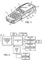
- Fig. 1 shows a preferred embodiment of a phone according to the invention, and it will be seen that the phone, which is generally designated by 1, comprises a user interface having a keypad 2, a display 3, an on/off button 4 fig. 3), a speaker 5 (only openings are shown in fig. 1), and a microphone 6 (only openings are shown in fig. 1).
- the phone 1 according to the preferred embodiment is adapted for communication via a cellular network, but could have been designed for a cordless network as well.
- the keypad 2 has a first group 7 of keys as alphanumeric keys, a soft key 8, and a navigation key 10. Furthermore the keypad includes a "clear" key 9. The present functionality of the soft key 8 is shown in separate fields in the display 3 just above the key 8. This key lay out is a characteristic of the Nokia 3110TM phone and the Nokia 5110TM phone.
- Fig. 2 schematically shows the most important parts of a preferred embodiment of the phone, said parts being essential to the understanding of the invention.
- the preferred embodiment of the phone of the invention is adapted for use in connection with the GSM 900MHz and GSM 1800 MHz network, but of course, the invention may also be applied in connection with other phone networks.
- the processor 18 controls the communication with the network via the transmitter/receiver circuit 19 and an antenna 20 that will be discussed in details below.
- the microphone 6 transforms the user's speech into analog signals, the analog signals formed thereby are A/D converted in an A/D converter (not shown) before the speech is encoded in an audio part 14.
- the encoded speech signal is transferred to the processor 18, which i.a. supports the GSM terminal software.
- the processor 18 also forms the interface to the peripheral units of the apparatus, including a RAM memory 17a and a Flash ROM memory 17b, a SIM card 16, the display 3 and the keypad 2 (as well as data, power supply, etc.).
- the audio part 14 speech-decodes the signal, which is transferred from the processor 18 to the earpiece 5 via a D/A converter (not shown).
- the phone 1 has an inner housing of which gripping areas 23 are visible. An exchangeable front cover 21 and rear cover 22 are snapped onto the inner housing.
- Fig. 3 shows the phone 1 with the rear cover 22 being removed.
- the phone 1 has an internal battery box that is also removed, whereby the user will have access to a SIM card terminal 25 according to the invention.
- the SIM card terminal 25 is placed just below the antenna 20 that is an internal antenna of the PIFA type.
- the SIM card terminal 25 includes a lid 26 for closing the terminal and the lid is shown in fig. 6, 7 and 9.
- the lid 26 has a plate formed part 38 from which two arms 28 extend. These two arms 28 are terminated in an eccentric portion 30 each having two aligned pins 29a and 29b defining the axis of rotation for the lid 26.
- the plate formed part 38 has a transversal aperture 31 that allows the user to inspect whether a SIM card has been inserted or not. Furthermore the aperture 31 increases the resiliency of the lid 26 in its longitudinal direction without loosing the stiffness in its transversal direction. Providing the end portion with transversal grooves 32 also supports this characteristic of the lid 26.
- the end portion has a locking tab 27 for locking the lid 26 relative to a metallic wall part 24 of the phone.
- the part of the lid 26 opposite to the mounting means formed as the arms 28 and pins 29a and 29b are more resilient than the remaining part of the lid 26.
- the lid 26 is clearly curved compared with a tangent line 39 of the arms 28.
- An appropriate material may be a polymer such as Polyacrylamid.
- Fig. 8 shows a printed circuit board (PCB) 37 used in the portable phone 1, and a terminal unit 35 is mounted (by soldering) as a separate connector unit on the PCB 37 whereby six connectors 36 are connected to the circuit on the PCB 37.
- the six connectors 36 are biased towards the SIM card when placed in the holder. Further components are shown on the PCB 37, but these are not relevant for the invention and are therefore not commented on.
- the metallic inner housing part 24 of the phone 1 is shown in fig. 4 and 5.
- the inner housing part 24 has a recess or a depression 44 for receiving the SIM card and the depression 44 has a punch out 41 in the bottom through which the terminal unit 35 is received.
- the lid 26 closes the depression 44.
- the side walls of the depression 44 is formed as guiding means for maintaining the position of the SIM card relative to said contact elements 36 of the terminal unit 35.
- the pivotal lid 26 is mounted pivotally to the housing part 24 for covering the depression 44 in a closed position.
- the pin 27 of the lid 26 and a punch out 23 in the depression act as locking means in order maintain the lid in a releasable locked position. Due to the resilient properties of the lid 26 the SIM card will be forced towards the contact elements 36 of the terminal unit 35 when the lid 26 is in the locked position.
- the two arms 28 of the lid 26 have orthogonal pins 29a and 29b acting as said shaft parts.
- the metallic inner wall part 24 has two slits 40 in continuation of the depression 44 for receiving said arms 28.
- the metallic inner wall part 24 has flaps 42 and 43 acting as bearing parts for the lid.
- a guide is provided defined by the PCB 37, the wall part 24 and two flaps 42 acting as stops for the guide.
- Fig. 11 shows schematically how the sliding movement of the lid 26 in closed position is allowed between two extreme positions.
- These flaps 43 have two depressions 45 for cooperation with the rounded tips of the pins 29b.
- the potential energy of the bearing/shaft structure will be minimum when the pins 29b engages the respective depression 45 on the flap.
Landscapes
- Engineering & Computer Science (AREA)
- Physics & Mathematics (AREA)
- General Physics & Mathematics (AREA)
- Theoretical Computer Science (AREA)
- Artificial Intelligence (AREA)
- Computer Vision & Pattern Recognition (AREA)
- Computer Networks & Wireless Communication (AREA)
- Signal Processing (AREA)
- Telephone Set Structure (AREA)
- Telephone Function (AREA)
- Coupling Device And Connection With Printed Circuit (AREA)
Abstract
Description
Claims (16)
- A holding mechanism for an integrated circuit card comprising:a housing part having a recess for receiving the integrated circuit card,a terminal unit provided in said depression having contact elements facing towards the integrated circuit card when inserted,said recess is formed with guiding means for maintaining the position of the integrated circuit card relatively to said contact elements of the terminal unit,a pivotal lid having means for mounting the lid to the housing part for covering the recess in a closed position,locking means for engaging the lid in order maintain the lid in a releasable locked position upon this engagement, andsaid lid being provided with biasing means biasing the integrated circuit card towards the contact elements of the terminal unit when the lid is in locked position.
- A holding mechanism according to claim 1, wherein the integrated circuit card is a Subscriber Identity Module for a portable phone.
- A holding mechanism according to claim 1, wherein the lid is provided as a curved structure and being elastically deformable.
- A holding mechanism according to claim 3 wherein the part of the lid opposite to the mounting means is more resilient than the remaining part of the lid.
- A holding mechanism according to claim 4 wherein the material used for said lid is Polyacrylamid.
- A portable phone having a holding mechanism for an integrated circuit card comprisinga housing part having a recess for receiving the integrated circuit card,a terminal unit provided in said depression having contact elements facing towards the integrated circuit card when inserted,said recess is formed with guiding means for maintaining the position of the integrated circuit card relatively to said contact elements of the terminal unit,a pivotal lid having means for mounting the lid to the housing part for covering the recess in a closed position,locking means for engaging the lid in order to maintain the lid in a releasable locked position upon this engagement, andsaid lid biasing the integrated circuit card towards the contact elements of the terminal unit when the lid is in locked position.
- A portable phone according to claim 6 wherein the housing part having a recess is integrated in a metallic wall part of the phone, and wherein the terminal unit is mounted on a printed circuit part of the phone and extends through a punch out in the bottom of said recess.
- A portable phone according to claim 6 wherein the guiding means of the recess is provided by the side walls of the recess.
- A portable phone according to claim 6 wherein the mounting means of the pivotal lid includes a shaft part for cooperation with a bearing part of the housing.
- A portable phone according to claim 9 wherein the pivotal lid has two arms extending in the longitudinal direction of the lid and said two arms have orthogonal pins acting as said shaft part.
- A portable phone according to claim 10 wherein the housing part is integrated in a metallic inner wall part of the phone, and wherein the bearing part is provided as two slits provided in the metallic wall part receiving said two arms of the lid.
- A portable phone according to claim 11 wherein the two slits together with the pins of the two arms of the lid defines at least two discrete rotation axes for said lid allowing a sliding movement of the lid in closed position between two extreme positions.
- A portable phone according to claim 12 wherein the locking means for lid includes a slot in the side wall of the recess opposite to the two slits provided receiving said two arms of the lid, and a tab on the lid opposite to the two arms, and said tab is received in the slot for locking the lid in one of said two extreme positions.
- A portable phone according to claim 6-13 wherein the lid is provided as a curved structure and being elastically deformable.
- A portable phone according to claim 14 wherein the part of the lid opposite to the mounting means is more resilient than the remaining part of the lid.
- A portable phone according to claim 15 wherein the material used for said lid is Polyacrylamid.
Applications Claiming Priority (2)
| Application Number | Priority Date | Filing Date | Title |
|---|---|---|---|
| GB9903257A GB2346726B (en) | 1999-02-12 | 1999-02-12 | Mechanism for holding an intergrated circuit card |
| GB9903257 | 1999-02-12 |
Publications (3)
| Publication Number | Publication Date |
|---|---|
| EP1028538A2 true EP1028538A2 (en) | 2000-08-16 |
| EP1028538A3 EP1028538A3 (en) | 2003-08-13 |
| EP1028538B1 EP1028538B1 (en) | 2005-06-29 |
Family
ID=10847685
Family Applications (1)
| Application Number | Title | Priority Date | Filing Date |
|---|---|---|---|
| EP00301071A Expired - Lifetime EP1028538B1 (en) | 1999-02-12 | 2000-02-11 | Mechanism for holding an integrated circuit card |
Country Status (4)
| Country | Link |
|---|---|
| US (1) | US6397081B1 (en) |
| EP (1) | EP1028538B1 (en) |
| DE (1) | DE60021000T2 (en) |
| GB (1) | GB2346726B (en) |
Cited By (3)
| Publication number | Priority date | Publication date | Assignee | Title |
|---|---|---|---|---|
| EP1195710A1 (en) * | 2000-10-03 | 2002-04-10 | Nokia Corporation | Smart card reader module |
| GB2376117B (en) * | 2001-01-15 | 2004-06-30 | Nec Corp | Sim card mounting structure for use in a mobile phone and a mobile phone incorporating the structure. |
| EP1655686A2 (en) | 2004-11-08 | 2006-05-10 | Lumberg Connect GmbH & Co. KG | Contact arrangement for a chip card, in particular a SIM or USIM card. |
Families Citing this family (13)
| Publication number | Priority date | Publication date | Assignee | Title |
|---|---|---|---|---|
| US20030181226A1 (en) * | 2000-02-23 | 2003-09-25 | Kaoru Kawata | Portable telephone battery pack and portable telephone equipped with the battery pack |
| JP4010730B2 (en) * | 2000-02-25 | 2007-11-21 | 松下電器産業株式会社 | Card holding structure and portable terminal equipped with the same |
| US6477357B1 (en) * | 2000-03-24 | 2002-11-05 | Qwest Communications International, Inc. | Customizable wireless device having stackable modules |
| US8407117B2 (en) * | 2002-04-24 | 2013-03-26 | Sk Planet Co., Ltd. | Mobile terminal with user identification card including personal finance-related information and method of using a value-added mobile service through said mobile terminal |
| TW563972U (en) * | 2002-12-27 | 2003-11-21 | Benq Corp | Mobile phone with SIM card holder |
| JP4021797B2 (en) * | 2003-04-28 | 2007-12-12 | 京セラ株式会社 | Mobile terminal device |
| US20050075138A1 (en) * | 2003-10-06 | 2005-04-07 | Page Kevin D. | Low profile electronic card holder and device using same |
| US20060121941A1 (en) * | 2004-12-03 | 2006-06-08 | Shiflett Jamie C | SIM card retaining device |
| CN1882227B (en) * | 2005-06-18 | 2010-04-07 | 深圳富泰宏精密工业有限公司 | Holding structure of chip card |
| US7764977B2 (en) * | 2006-05-24 | 2010-07-27 | Nokia Corporation | Memory card removal guard |
| US8682387B2 (en) * | 2006-10-18 | 2014-03-25 | William Frederick Ryann | Mobile device interface platform |
| TWI346522B (en) * | 2007-03-12 | 2011-08-01 | Asustek Comp Inc | Cellular phone sim card fastening mechanism |
| CN103326149B (en) * | 2013-05-21 | 2016-06-08 | 惠州Tcl移动通信有限公司 | Sim card connector and mobile terminal |
Family Cites Families (11)
| Publication number | Priority date | Publication date | Assignee | Title |
|---|---|---|---|---|
| WO1991015101A1 (en) | 1990-03-17 | 1991-10-03 | Amphenol-Tuchel Electronics Gmbh | Contactor device, especially for an sim |
| DE9012889U1 (en) * | 1990-09-10 | 1990-11-15 | Siemens AG, 8000 München | Card reader for electrical communications |
| ES2061121T3 (en) | 1991-06-28 | 1994-12-01 | Molex Inc | C I CARD CONNECTOR (INTEGRATED CIRCUITS). |
| US5661634A (en) * | 1993-11-09 | 1997-08-26 | Fujitsu Limited | Information processing system using portable terminal unit and data communication adapter therefor |
| DE19521721B4 (en) | 1995-06-14 | 2006-12-07 | Amphenol-Tuchel Electronics Gmbh | Shielded contacting device |
| FR2743464A1 (en) * | 1996-01-10 | 1997-07-11 | Philips Electronics Nv | APPARATUS HAVING A REMOVABLE HOUSING CONTAINING AN ADAPTER FOR READING DIFFERENT FORMAT OF CHIP CARDS |
| FR2745403A1 (en) | 1996-02-28 | 1997-08-29 | Philips Electronics Nv | CARD READER FOR PORTABLE TELEPHONE AND PORTABLE TELEPHONE INCORPORATING THE SAME |
| US5894597A (en) | 1996-09-24 | 1999-04-13 | Motorola, Inc. | Communication device for different sized cards |
| GB2331637A (en) * | 1996-09-26 | 1999-05-26 | Whitaker Corp | Electronic module connector having a rotatable cover |
| US6015311A (en) * | 1996-12-17 | 2000-01-18 | The Whitaker Corporation | Contact configuration for smart card reader |
| US5883786A (en) | 1996-12-31 | 1999-03-16 | Ericsson, Inc. | SIM card containment assembly for an electronic apparatus |
-
1999
- 1999-02-12 GB GB9903257A patent/GB2346726B/en not_active Expired - Fee Related
-
2000
- 2000-02-11 US US09/502,513 patent/US6397081B1/en not_active Expired - Lifetime
- 2000-02-11 EP EP00301071A patent/EP1028538B1/en not_active Expired - Lifetime
- 2000-02-11 DE DE60021000T patent/DE60021000T2/en not_active Expired - Lifetime
Cited By (4)
| Publication number | Priority date | Publication date | Assignee | Title |
|---|---|---|---|---|
| EP1195710A1 (en) * | 2000-10-03 | 2002-04-10 | Nokia Corporation | Smart card reader module |
| GB2376117B (en) * | 2001-01-15 | 2004-06-30 | Nec Corp | Sim card mounting structure for use in a mobile phone and a mobile phone incorporating the structure. |
| EP1655686A2 (en) | 2004-11-08 | 2006-05-10 | Lumberg Connect GmbH & Co. KG | Contact arrangement for a chip card, in particular a SIM or USIM card. |
| EP1655686A3 (en) * | 2004-11-08 | 2008-02-27 | Lumberg Connect GmbH | Contact arrangement for a chip card, in particular a SIM or USIM card. |
Also Published As
| Publication number | Publication date |
|---|---|
| GB2346726B (en) | 2003-05-07 |
| EP1028538A3 (en) | 2003-08-13 |
| GB9903257D0 (en) | 1999-04-07 |
| EP1028538B1 (en) | 2005-06-29 |
| DE60021000D1 (en) | 2005-08-04 |
| US6397081B1 (en) | 2002-05-28 |
| GB2346726A (en) | 2000-08-16 |
| DE60021000T2 (en) | 2006-05-04 |
Similar Documents
| Publication | Publication Date | Title |
|---|---|---|
| US6397081B1 (en) | Mechanism for holding an integrated circuit card | |
| EP1123583B3 (en) | Data card connector | |
| AU724143B2 (en) | Subscriber identity module (SIM) card holder | |
| US6600662B1 (en) | Light guide for a foldable electronic device | |
| US7746635B2 (en) | Chip card catching mechanism and portable electronic device using the same | |
| US6424842B1 (en) | Dual function connector for cellular phones | |
| US20020187806A1 (en) | Portable communication device for minimizing specific absorption rate (SAR) value of electromagnetic waves | |
| US20100279694A1 (en) | Display panel structure, electronic device using the same, and mobile information equipment | |
| JP3250789B2 (en) | Electrical connector for cards with surface contacts | |
| US6831977B2 (en) | Cover for a telephone handset | |
| US20060286847A1 (en) | Sim card holder | |
| EP1646208B1 (en) | SIM/UIM card socket in slidable portable wireless terminal | |
| US7764977B2 (en) | Memory card removal guard | |
| US7949379B2 (en) | Foldable electronic device | |
| EP1536365B1 (en) | Card holding structure for portable electronic device | |
| US7344401B2 (en) | Surface contact card holder | |
| JP3439868B2 (en) | Mobile phone | |
| US8248819B2 (en) | Chip card holder for portable electronic device | |
| EP4398424B1 (en) | Card holder structure, card holder assembly and electronic apparatus | |
| GB2376117A (en) | Sim card mounting structure for use in a mobile phone | |
| JP2006109456A (en) | Mobile communication terminal | |
| WO2001080437A1 (en) | Mobile telephone accessory | |
| JP2003304313A (en) | Card holder and portable terminal provided with the same | |
| US20020060248A1 (en) | Card reader connector | |
| US20030012369A1 (en) | Locking arrangement for a subscriber terminal device |
Legal Events
| Date | Code | Title | Description |
|---|---|---|---|
| PUAI | Public reference made under article 153(3) epc to a published international application that has entered the european phase |
Free format text: ORIGINAL CODE: 0009012 |
|
| AK | Designated contracting states |
Kind code of ref document: A2 Designated state(s): AT BE CH CY DE DK ES FI FR GB GR IE IT LI LU MC NL PT SE |
|
| AX | Request for extension of the european patent |
Free format text: AL;LT;LV;MK;RO;SI |
|
| RAP1 | Party data changed (applicant data changed or rights of an application transferred) |
Owner name: NOKIA CORPORATION |
|
| PUAL | Search report despatched |
Free format text: ORIGINAL CODE: 0009013 |
|
| AK | Designated contracting states |
Designated state(s): AT BE CH CY DE DK ES FI FR GB GR IE IT LI LU MC NL PT SE |
|
| AX | Request for extension of the european patent |
Extension state: AL LT LV MK RO SI |
|
| 17P | Request for examination filed |
Effective date: 20040213 |
|
| AKX | Designation fees paid |
Designated state(s): DE FR IT SE |
|
| 17Q | First examination report despatched |
Effective date: 20040511 |
|
| GRAP | Despatch of communication of intention to grant a patent |
Free format text: ORIGINAL CODE: EPIDOSNIGR1 |
|
| GRAS | Grant fee paid |
Free format text: ORIGINAL CODE: EPIDOSNIGR3 |
|
| GRAA | (expected) grant |
Free format text: ORIGINAL CODE: 0009210 |
|
| AK | Designated contracting states |
Kind code of ref document: B1 Designated state(s): DE FR IT SE |
|
| PG25 | Lapsed in a contracting state [announced via postgrant information from national office to epo] |
Ref country code: IT Free format text: LAPSE BECAUSE OF FAILURE TO SUBMIT A TRANSLATION OF THE DESCRIPTION OR TO PAY THE FEE WITHIN THE PRE;WARNING: LAPSES OF ITALIAN PATENTS WITH EFFECTIVE DATE BEFORE 2007 MAY HAVE OCCURRED AT ANY TIME BEFORE 2007. THE CORRECT EFFECTIVE DATE MAY BE DIFFERENT FROM THE ONE RECORDED.SCRIBED TIME-LIMIT Effective date: 20050629 |
|
| REF | Corresponds to: |
Ref document number: 60021000 Country of ref document: DE Date of ref document: 20050804 Kind code of ref document: P |
|
| PG25 | Lapsed in a contracting state [announced via postgrant information from national office to epo] |
Ref country code: SE Free format text: LAPSE BECAUSE OF FAILURE TO SUBMIT A TRANSLATION OF THE DESCRIPTION OR TO PAY THE FEE WITHIN THE PRESCRIBED TIME-LIMIT Effective date: 20050929 |
|
| ET | Fr: translation filed | ||
| PLBE | No opposition filed within time limit |
Free format text: ORIGINAL CODE: 0009261 |
|
| STAA | Information on the status of an ep patent application or granted ep patent |
Free format text: STATUS: NO OPPOSITION FILED WITHIN TIME LIMIT |
|
| 26N | No opposition filed |
Effective date: 20060330 |
|
| REG | Reference to a national code |
Ref country code: DE Ref legal event code: R082 Ref document number: 60021000 Country of ref document: DE Representative=s name: BECKER, KURIG, STRAUS, DE Ref country code: DE Ref legal event code: R081 Ref document number: 60021000 Country of ref document: DE Owner name: NOKIA TECHNOLOGIES OY, FI Free format text: FORMER OWNER: NOKIA CORP., 02610 ESPOO, FI |
|
| REG | Reference to a national code |
Ref country code: FR Ref legal event code: PLFP Year of fee payment: 17 |
|
| REG | Reference to a national code |
Ref country code: FR Ref legal event code: PLFP Year of fee payment: 18 |
|
| REG | Reference to a national code |
Ref country code: FR Ref legal event code: TP Owner name: NOKIA TECHNOLOGIES OY, FI Effective date: 20170109 |
|
| PGFP | Annual fee paid to national office [announced via postgrant information from national office to epo] |
Ref country code: FR Payment date: 20170112 Year of fee payment: 18 Ref country code: DE Payment date: 20170207 Year of fee payment: 18 |
|
| REG | Reference to a national code |
Ref country code: DE Ref legal event code: R119 Ref document number: 60021000 Country of ref document: DE |
|
| REG | Reference to a national code |
Ref country code: FR Ref legal event code: ST Effective date: 20181031 |
|
| PG25 | Lapsed in a contracting state [announced via postgrant information from national office to epo] |
Ref country code: DE Free format text: LAPSE BECAUSE OF NON-PAYMENT OF DUE FEES Effective date: 20180901 |
|
| PG25 | Lapsed in a contracting state [announced via postgrant information from national office to epo] |
Ref country code: FR Free format text: LAPSE BECAUSE OF NON-PAYMENT OF DUE FEES Effective date: 20180228 |
|
| REG | Reference to a national code |
Ref country code: DE Ref legal event code: R082 Ref document number: 60021000 Country of ref document: DE Representative=s name: BARKHOFF REIMANN VOSSIUS, DE Ref country code: DE Ref legal event code: R081 Ref document number: 60021000 Country of ref document: DE Owner name: WSOU INVESTMENTS, LLC, LOS ANGELES, US Free format text: FORMER OWNER: NOKIA TECHNOLOGIES OY, ESPOO, FI |