EP1028450A1 - Getter for use in evacuated tube envelopes - Google Patents
Getter for use in evacuated tube envelopes Download PDFInfo
- Publication number
- EP1028450A1 EP1028450A1 EP00300934A EP00300934A EP1028450A1 EP 1028450 A1 EP1028450 A1 EP 1028450A1 EP 00300934 A EP00300934 A EP 00300934A EP 00300934 A EP00300934 A EP 00300934A EP 1028450 A1 EP1028450 A1 EP 1028450A1
- Authority
- EP
- European Patent Office
- Prior art keywords
- getter
- tube
- envelope
- conductor
- cathode
- Prior art date
- Legal status (The legal status is an assumption and is not a legal conclusion. Google has not performed a legal analysis and makes no representation as to the accuracy of the status listed.)
- Withdrawn
Links
- 239000004020 conductor Substances 0.000 claims abstract description 73
- 230000003213 activating effect Effects 0.000 claims description 23
- 230000004044 response Effects 0.000 claims description 11
- 238000004891 communication Methods 0.000 claims description 6
- 239000003990 capacitor Substances 0.000 claims description 5
- 239000000835 fiber Substances 0.000 claims description 3
- 230000005540 biological transmission Effects 0.000 claims 1
- 239000000463 material Substances 0.000 description 45
- 239000007789 gas Substances 0.000 description 43
- 238000000034 method Methods 0.000 description 27
- 230000008569 process Effects 0.000 description 14
- 238000003384 imaging method Methods 0.000 description 10
- 239000000356 contaminant Substances 0.000 description 7
- 230000008901 benefit Effects 0.000 description 6
- 238000002591 computed tomography Methods 0.000 description 6
- 238000013461 design Methods 0.000 description 6
- 238000004519 manufacturing process Methods 0.000 description 6
- 229910052751 metal Inorganic materials 0.000 description 6
- 239000002184 metal Substances 0.000 description 6
- 238000005086 pumping Methods 0.000 description 4
- 239000011521 glass Substances 0.000 description 3
- 238000010438 heat treatment Methods 0.000 description 3
- 238000001179 sorption measurement Methods 0.000 description 3
- 238000004544 sputter deposition Methods 0.000 description 3
- 238000004804 winding Methods 0.000 description 3
- 238000004458 analytical method Methods 0.000 description 2
- 238000006243 chemical reaction Methods 0.000 description 2
- 230000007423 decrease Effects 0.000 description 2
- 238000001514 detection method Methods 0.000 description 2
- 238000010586 diagram Methods 0.000 description 2
- 230000005684 electric field Effects 0.000 description 2
- 230000005672 electromagnetic field Effects 0.000 description 2
- 238000001704 evaporation Methods 0.000 description 2
- 238000012986 modification Methods 0.000 description 2
- 230000004048 modification Effects 0.000 description 2
- 238000012544 monitoring process Methods 0.000 description 2
- 238000012360 testing method Methods 0.000 description 2
- RTAQQCXQSZGOHL-UHFFFAOYSA-N Titanium Chemical compound [Ti] RTAQQCXQSZGOHL-UHFFFAOYSA-N 0.000 description 1
- 230000004913 activation Effects 0.000 description 1
- 238000013459 approach Methods 0.000 description 1
- 229910052788 barium Inorganic materials 0.000 description 1
- DSAJWYNOEDNPEQ-UHFFFAOYSA-N barium atom Chemical compound [Ba] DSAJWYNOEDNPEQ-UHFFFAOYSA-N 0.000 description 1
- 230000015556 catabolic process Effects 0.000 description 1
- 150000001875 compounds Chemical class 0.000 description 1
- 230000008878 coupling Effects 0.000 description 1
- 238000010168 coupling process Methods 0.000 description 1
- 238000005859 coupling reaction Methods 0.000 description 1
- 238000006731 degradation reaction Methods 0.000 description 1
- 238000000151 deposition Methods 0.000 description 1
- 238000009792 diffusion process Methods 0.000 description 1
- 230000003292 diminished effect Effects 0.000 description 1
- 230000000694 effects Effects 0.000 description 1
- 230000006698 induction Effects 0.000 description 1
- 230000001939 inductive effect Effects 0.000 description 1
- 238000009434 installation Methods 0.000 description 1
- 238000012423 maintenance Methods 0.000 description 1
- 229910000986 non-evaporable getter Inorganic materials 0.000 description 1
- 230000005855 radiation Effects 0.000 description 1
- 238000009877 rendering Methods 0.000 description 1
- 238000009420 retrofitting Methods 0.000 description 1
- 238000003860 storage Methods 0.000 description 1
- 229910052715 tantalum Inorganic materials 0.000 description 1
- GUVRBAGPIYLISA-UHFFFAOYSA-N tantalum atom Chemical compound [Ta] GUVRBAGPIYLISA-UHFFFAOYSA-N 0.000 description 1
- 239000010936 titanium Substances 0.000 description 1
- 229910052719 titanium Inorganic materials 0.000 description 1
- 238000004846 x-ray emission Methods 0.000 description 1
Images


Classifications
-
- H—ELECTRICITY
- H01—ELECTRIC ELEMENTS
- H01J—ELECTRIC DISCHARGE TUBES OR DISCHARGE LAMPS
- H01J9/00—Apparatus or processes specially adapted for the manufacture, installation, removal, maintenance of electric discharge tubes, discharge lamps, or parts thereof; Recovery of material from discharge tubes or lamps
- H01J9/38—Exhausting, degassing, filling, or cleaning vessels
- H01J9/385—Exhausting vessels
-
- H—ELECTRICITY
- H01—ELECTRIC ELEMENTS
- H01J—ELECTRIC DISCHARGE TUBES OR DISCHARGE LAMPS
- H01J35/00—X-ray tubes
- H01J35/02—Details
- H01J35/20—Selection of substances for gas fillings; Means for obtaining or maintaining the desired pressure within the tube, e.g. by gettering
-
- H—ELECTRICITY
- H01—ELECTRIC ELEMENTS
- H01J—ELECTRIC DISCHARGE TUBES OR DISCHARGE LAMPS
- H01J2235/00—X-ray tubes
- H01J2235/20—Arrangements for controlling gases within the X-ray tube
- H01J2235/205—Gettering
Definitions
- the present invention relates to getters for use in evacuated tube envelopes and is particularly related to an apparatus for use in improving the performance and/or extending the service life of an x-ray tube by selectively improving performance of gas pressure reducing materials in x-ray tubes installed in operating x-ray imaging systems.
- the present invention finds particular application in conjunction with activating a getter by depositing and/or actuating getter material surface area in x-ray tubes installed in operating imaging systems when improved getter pumping rates are desired. It will be appreciated, however, that the invention is applicable in other applications where it is necessary to improve getter pumping rate in a vacuum tube or envelope.
- Production of a tube or envelope that can maintain an adequate vacuum during operation includes removing residual contaminants left on the tube components. During manufacture the tube components are cleaned and baked in vacuum furnaces. This procedure reduces the amount of surface contaminants available to evolve into gases when the tubes are in service.
- the cleaned x-ray tube components are then assembled and placed within an envelope.
- the envelope is evacuated using a vacuum pump and sealed from the outside environment. During the pumping process the x-ray tube is heated to further reduce contaminants.
- a getter material typically is located in the vacuum envelope. After the vacuum pump has established a vacuum, the getter material is activated. Depending on the type of material, getters are classified as either (i) evaporable or (ii) non-evaporable e.g, a bulk getter. Activating the getter material may include (i) flashing the getter for an evaporable material or (ii) actuating the getter by raising its temperature for a bulk or non-evaporable getter.
- One method of activating (flashing) an evaporable getter is accomplished by locating a source for an electromagnetic field, usually an RF field, outside the evacuated envelope proximate to the getter coil located inside the envelope.
- the electromagnetic field is generated and couples with the getter coil, thereby inducing current flow in the coil and heating the getter material in contact with the coil.
- the heated getter material evaporates and atoms leaving the getter surface are deposited on interior surfaces of the envelope and other internal components.
- the freshly deposited getter material plated on the interior surfaces absorb additional amounts of residual gas molecules.
- Another method of activating the getter by flashing includes applying electric current directly to the getter material via dedicated terminals.
- the getter is heated by resistance heating thereby raising the temperature of the getter material to that necessary to evaporate the getter.
- the getter film produced by flashing reacts with all the residual active gases and, by chemisorption, removes them from the gas phase to further reduce the gas pressure within the evacuated envelope.
- the sorption capacity of the deposited getter material is limited. As sorption capacity is approached, the ability of the getter to sorb additional gas molecules is diminished.
- the reacted layer includes oxides and additional compounds that include the other evolved and absorbed gases.
- Non-evaporable, or bulk, getters are temperature activated and do not need to be evaporated to be activated. These types of getters are activated by supplying specified electric current levels to the getter causing resistance heating to elevate the getter material to a desired temperature. Once the getter reaches the desired temperature the specific gas molecules are absorbed into the getter. The vacuum in the x-ray tube may be getter pumped to the desired gas pressure level using either a flashed getter or a bulk getter.
- the completed x-ray tube is then mounted into the housing or enclosure that is filled with dielectric oil.
- the components continue to evolve gas into the evacuated envelope.
- the evolved gas is also produced from contaminants that migrate via diffusion through the tube components to their surfaces. These gases react with the getter material that was flashed during the original manufacturing process. As the tube continues to operate and contaminants are absorbed by the getter, sorption capacity of the getter material is reached. The getter material becomes less efficient in removing gas molecules and the gas pressure in the evacuated envelope increases.
- a current on the order of hundreds of amperes can flow between the cathode and the anode.
- an avalanche type effect may occur, sputtering metal and metal atoms as well as ionising the contaminants in the vacuum.
- arcing in an x-ray tube used in a Computed Tomography (CT) imaging system contaminates the signal collected at the detectors and affects proper image reconstruction. This may result in an un-usable set of data requiring another CT scan of the patient.
- CT Computed Tomography
- Arcing typically occurs in the area of the x-ray tube having the highest electric field strength. As such, arcing in an x-ray tube may commonly occur in the same region as where the cathode is supplying the anode with electrons for the production of x-ray emissions.
- the sputtering of metal from the cathode produced during arcing often lands on the internal surface of the glass envelope in proximity to the cathode. The existence of the metal deposits on the glass envelope can deleteriously affect x-ray tube performance. Sputtering of metal within the envelope may increase as internal pressure increases, even in the absence of an arc.
- An apparatus in accordance with one embodiment of the present invention includes an evacuated tube envelope and an electrode in the tube envelope.
- a getter is installed in the tube envelope and is electrically connected to a conductor.
- the conductor is electrically connected to both of the getter and the electrode.
- the apparatus includes means for selectively providing electrical energy through the conductor to one of the electrode and the getter.
- the apparatus includes a cathode as the electrode.
- Another limited aspect of the present invention includes at least a diode or inductor as the means for selectively providing electrical energy to the getter.
- an x-ray tube comprises a substantially evacuated envelope.
- An anode is located within the envelope.
- a cathode filament is located in the envelope.
- the x-ray tube further includes at least one getter located within the envelope. At least one conductor is included that is electrically connected to both of the cathode filament and the getter.
- the x-ray tube includes a plurality of getters within the tube and the apparatus includes means for selectively activating at least one of the plurality of getters.
- the x-ray tube includes a diode in the means for selectively activating the at least one of the plurality of getters.
- a capacitor is included in the means for selectively activating the at least one of the plurality of getters.
- the diode (or capacitor) is connected in series with the cathode filament.
- an apparatus for activating a getter in yet another aspect of the present invention, includes an enclosed tube having a tube wall.
- the getter is electrically connected to at least one conductor extending through the tube wall.
- the apparatus comprises means for providing a signal indicative of tube performance.
- the apparatus also includes means for selectively activating one of the electrode and the getter in response to the signal indicative of tube performance.
- the selective activating means includes a controller in data communication with the signal providing means.
- the signal indicative of tube performance includes a signal indicative of at least one of arc rate, gas pressure, operating cycles, starts, exposures, number of scans, current, voltage and temperature.
- an apparatus for controllably activating a getter in an envelope comprises a pressure measuring device advantageously located to determine a measure of the gas pressure within the envelope.
- the pressure measuring device provides a signal indicative of a measure of the gas pressure within the envelope.
- a source of electrical energy is operatively connected to the getter and a controller is controllably connected to both of (i) the pressure measuring device and (ii) the source of electrical energy. The controller activates the source of electrical energy in response to the signal provided by the pressure measuring device.
- the controller determines the amount of electrical energy to apply to the getter in response to the signal provided by the pressure measuring device.
- the pressure measuring device is an ionisation gauge that includes an anode and a cathode located within the envelope.
- an apparatus comprises an envelope that is substantially evacuated having a first getter located within the envelope.
- the first getter has a first end electrically connected to a first terminal extending through the envelope and a second end electrically connected to a second terminal extending through the envelope.
- a second getter located within the envelope.
- the second getter has a first end electrically connected to a third terminal extending through the envelope and a second end electrically connected to at least one of the first and second terminal.
- a method for maintaining a pressure level in an enclosed evacuated electrode tube.
- the method comprises the steps of providing a signal indicative of tube performance and activating getter material in response to the signal indicative of tube performance.
- the signal indicative of tube performance includes at least one of arc rate, gas pressure, exposure count, number of scans, operating cycles, starts, current, voltage and temperature.
- the step of activating the getter includes the step of evaporating getter material.
- the method includes the step of determining the amount of getter material to activate prior to the step of activating.
- the step of activating the getter includes the step of controlling the amount of getter material evaporated. And a further limited aspect includes a step of evaporating only a portion of the getter material for a discrete activation step. And yet another limited aspect of the present invention includes the step of determining the amount of getter material remaining.
- the method includes the steps of monitoring the signals indicative of tube performance and storing values associated with the monitored signals.
- a method of maintaining a substantial vacuum in an x-ray tube comprises the steps of sensing gas pressure in the tube, providing a signal indicative of the gas pressure and activating the getter material in response to the signal.
- an imaging apparatus comprises an x-ray source including an envelope that is substantially evacuated, an anode located within the envelope, and a cathode filament located in the envelope. At least one getter is located within the envelope. Means are provided for activating the getter and the apparatus includes an x-ray detector.
- the apparatus further includes a member with an arcuate surface wherein the x-ray detector comprises a plurality of detectors disposed on the arcuate surface of the member.
- a method for flashing a getter in an x-ray tube in an installed imaging system.
- the method includes the steps of determining the desirability of activating the getter based upon tube operating characteristics and the step of activating the getter.
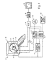
- a medical diagnostic apparatus 20 is used to examine with x-rays a subject (not shown) in an examination region 22. More specifically, an x-ray tube 24 projects radiation through the examining region 22 and on to an x-ray detector assembly 26.
- the x-ray detector assembly 26 is disposed on an arcuate surface in a ring 28 on a gantry 30. The detected x-rays are converted into electrical signals which, in turn, are reconstructed into diagnostic images.
- x-ray detection systems other than the described CT embodiment may be used with the present invention.
- the medical diagnostic apparatus can be one that produces projection or shadowgraphic images on x-ray sensitive photographic film.
- Another alternative x-ray diagnostic apparatus can be a digital x-ray system which generates shadowgraphic x-ray images in single or multiple energies electronically.
- Yet another apparatus includes fluoroscopic imaging systems.
- non-medical x-ray detection systems are also contemplated as well as other medical x-ray medical diagnostic systems.
- the x-ray detector assembly 26 and a tachometer or angular position encoder 32 for detecting rotation or angular position of the x-ray source 24 are connected with an image reconstruction processor 34.
- the image reconstruction processor 34 utilises conventional convolution and back projection or other reconstruction algorithms as are known in the art.
- the reconstruction processor 34 produces an electronic image representation for storage in an image memory 36.
- a video processor formats the reconstructed image data into a selected format such as a slice, projection, surface rendering, sculptured volumes and the like.
- An alternating current (AC) source of power 40 is connected to an x-ray tube power supply and control 42.
- the x-ray tube 24 is operatively connected to the tube power supply and control 42.
- a diagnostic system monitor and memory 44 is in data communication with a plurality of components of the diagnostic apparatus 20 to monitor and store desired performance characteristics to provide signals indicative of system performance. Some of the signals that are monitored are indicative of, gas pressure in the x-ray tube, arc rate, operating cycles, exposure count, number of scans, anode and cathode current and voltage, temperature, anode and cathode voltage balance, anode rotation, and a number of other desirable operating parameters known in the art.
- An example of a suitable monitoring system is described in U.S. Patent Number 4,853,946 to Elliott et al., entitled “Diagnostic Service System for CT Scanners" which is incorporated herein by reference.
- the systems monitor and memory 44 is in data communication with the tube power supply and control 42 and a scanner systems control 46.
- the scanner systems control 46 is a suitable computer or microcomputer with all required systems and memory for operating the diagnostic device 20.
- the systems control 46 includes sufficient memory capacity to store data for controlling various scanner and tube operations in look up tables or as algorithms as desired.
- the scanner systems control 46 is controllably connected with and in data communication with the operative components of the medical diagnostic apparatus 20 in a manner known in the art.
- Input and output devices 48 are connected to the scanner systems control 46.
- Input and output devices 48 may include a field service diagnostics device, an operators console, communications devices and modems, printers, monitors and other devices as appropriate.
- the systems control 46 manages and controls the operation of the diagnostic apparatus 20 in response to (i) inputs received from the monitored components of the apparatus 20, (ii) system operators and (iii) field service technicians via the input and output devices 48.
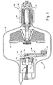
- the x-ray tube 24 includes an evacuated envelope 50 in which an anode 52 is rotatably mounted.
- the envelope 50 is preferably made of glass or metal and may be constructed of other suitable materials.
- the anode 52 is connected to a shaft 54 which is connected to an induction motor 56.
- the motor 56 includes rotor windings 58 and associated bearings (not shown) are mounted in a neck portion 60 of the evacuated envelope 50.
- the rotor windings 58 are electromagnetically coupled with a main stator winding 62 on the outside of the neck portion 60.
- the anode 52 is rotated at high speed during tube operation. It is to be appreciated that the present invention is also applicable to stationary anode x-ray tubes and other electrode vacuum tubes.
- a cathode 64 is supported in the envelope 50 on a cathode support assembly 66.
- the cathode support assembly 66 is fixedly attached a cathode conductor feed through and header assembly 68 that is ultimately secured to the envelope 50 with a vacuum tight seal (not shown).
- a getter shield 70 is joined to the header assembly 68.
- a getter 72 is attached to the feed through and header assembly 68.
- Cathode conductors 74a, b, c are electrically connected to feed through terminals 76 that extend through the header assembly and are connected to a plurality of conductors. Since the electrical interconnections between terminals and conductors are not apparent in this figure, the arrangement of the cathode conductors in FIG. 2 are not necessarily indicative of a specific embodiment of the present invention but is representative of an example of a physical arrangement for feeding conductors through a header to components within the envelope 50. Actual circuit connections for the cathode conductors and getters to the terminals 106 a-d according to the present invention are described and illustrated in accordance with FIGS. 3 - 8 below. Like numerals are used for similar elements in the different embodiments of the present invention.
- the x-ray tube 24, of FIG. 2 is mounted within an oil filled housing 100 in a manner known in the art.
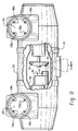
- the housing is equipped with the necessary high voltage connectors 102, 104 and cathode terminals 106a-d and anode terminals 108a-d to provide electrical power to the enclosed x-ray tube 24.
- FIG. 11 illustrates four terminals in the high voltage connectors 102, 104, some x-ray tubes and housings have only three terminals contained therein.
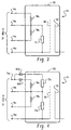
- Conductor 74a is connected to a first end of a first cathode filament 78a.
- Conductor 74b is connected to (i) a second end of the cathode filament 78a, (ii) a first end of a second cathode filament 78b, and (iii) a first end of getter 72.
- Conductor 74c is connected to a second end of the second cathode filament 78b.
- the conductor 74d is connected to a second end of getter 72 and to a cathode grid cup 80.
- Presently designed and installed imaging systems have high voltage connectors with a fixed number of conductor terminals or contacts, e.g. a four (4) pin connector. Flashing the getter 72 in the field using an x-ray tube according to the present invention can be accomplished in presently designed imaging systems by removal of the four pin high voltage connector (not shown) on the cathode side of the x-ray tube housing and having the service technician apply the desired voltage and current to terminals 74b and 74d to flash the getter and deposit the desired amount of getter material within the envelope 50.
- the current flow in the getter conductors heats the getter material in contact with the conductors.
- the heated getter material evaporates and atoms leaving the getter surface are deposited on interior surfaces of the envelope and other internal components.
- the freshly deposited getter material plated on the interior surfaces absorb additional amounts of residual gas molecules.
- the tube may remain within the oil filled tube housing during this process.
- the flashed getter is activated since the reacted layer is now plated over with fresh material.
- a bulk getter may be actuated by having electric current applied to it for a predetermined period of time.
- the bulk getter thereby has its temperature raised to that required to absorb specific gas molecules.
- the getter is actuated for the time period required to pump a sufficient number of the evolved gas molecules and reduce the gas pressure in the tube.
- an x-ray tube and associated housing be provided such that a getter has dedicated conductors.
- the getter conductors are advantageously connected to permit flashing of the getter in the field without requiring the removal of the high voltage connection.
- Such getter conductors could be easily accessible on new tube and housing designs to a service technician or permenanently connected to a proper source of electrical energy that may be manually or automatically controlled to activate the getter by flashing or actuating.
- Another embodiment of the present invention includes diodes 82a, 82b to direct the flow of desired DC current in the cathode filament an x-ray tube.
- the cathode of the diode 82a is connected to the conductor 74a.
- the anode of the diode 82a is connected to a first end of a getter 72a.
- a second end of the getter 72a is connected to the conductor 74b.
- the anode of the diode 82b is connected to the conductor 74a and the cathode of the diode 82b is connected to the cathode filament 78a.
- the other end of the cathode filament 78a is connected to the conductor 74b.
- a second getter 72b is connected to the conductor 74b and to the conductor 74d.
- a second cathode filament 78b is connected to the conductor 74b and the conductor 74c.
- the cathode grid cup 80 is connected to the conductor 74d.
- the cathode filament 78a is energised using conductors 74a, 74b.
- the diode 82b permits the desired and appropriately polarised DC current to flow from conductor 74a through the cathode filament 78a.
- the getter 72a is flashed by reversing the DC polarity on the conductors 74b, 74a such that the diode 82a permits flow of appropriate current from conductor 74b through the getter 72a and conductor 74a.
- This embodiment of the present invention has five conductors exiting the tube envelope 50 but still has only four conductor terminals for the four pin high voltage connector (not shown) to be connected with the four conductors 74a, b, c, d. It is to be appreciated that the diodes may be located within the envelope 50 thereby having only four conductors exiting the tube envelope 50.
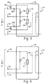
- Diodes 82a, 82b and 84a, 84b direct the flow of desired DC current in the cathode filament of an x-ray tube.
- the cathode of the diode 82a is connected to the conductor 74a.
- the anode of the diode 82a is connected to a first end of a getter 72a.
- a second end of the getter 72a is connected to the conductor 74b.
- the anode of the diode 82b is connected to the conductor 74a and its cathode is connected to the cathode filament 78a.
- the other end of the cathode filament 78a is connected to the conductor 74b.
- a second getter 72b is connected to the conductor 74b and to the anode of a diode 84a.
- the cathode of the diode 84a is connected to the conductor 74c.
- a second cathode filament 78b is connected to the conductor 74b and the cathode of a diode 84b.
- the anode of the diode 84b is connected to conductor 74c.
- the cathode grid cup 80 is connected to the conductor 74d.
- This embodiment of the present invention has six conductors exiting the tube envelope 50 but still has only four conductor terminals for the four pin high voltage connector (not shown) to be connected with the four conductors 74a, b, c, d. It is to be appreciated that the diodes may be located within the envelope 50 thereby having only four conductors exiting the tube envelope 50.
- This arrangement permits using the components of the x-ray tube to monitor gas pressure in the evacuated envelope with known ionisation gauge techniques. Basically electrons are accelerated between the cathode and the grid, but cannot reach the anode since it is connected at a negative potential. Some electrons, however, collide with gas molecules in the tube and ionise them, leaving them positively charged. The positively charged gas molecules then go to the anode and the anode current produced provides a measure indicative of the number of gas molecules present in the evacuated envelope.
- FIG. 6 another embodiment of the present invention is shown that has a single cathode filament 78 attached between the conductors 74a and 74b.
- a single getter 72 is attached between the conductors 74a and 74c.
- the cathode grid cup 80 is connected to the conductor 74c.
- the x-ray tube 24 is one that applies alternating current (AC) to the cathode filaments 78a, 78b through the conductors 74a, 74b, and 74c.
- a capacitor 86 is connected between the conductor 74c and the cathode filament 78b.
- the other end of the cathode filament 78b is connected to conductor 74b.
- the cathode filament 78a is connected between the conductors 74a and 74b.
- one end of the getter 72 is connected to the conductor 74b and the other end is connected to one terminal of an inductor 88.
- the other end of the inductor 88 is connected to the conductor 74c.
- the cathode grid cup 80 is connected to the inductor 88 and the getter 72.
- the filaments 78a, 78b operate with AC current supplied between conductor 74b and 74a or 74c. Under normal operation, the inductor 88 resists the flow of AC current through the getter 72 to a level insufficient to flash the getter.
- the capacitor 86 is advantageously selected to permit flow of sufficient AC current through the cathode filament 78b for tube operation and to effectively limit DC current in the filament during getter flashing. To flash the getter 72, DC current is applied by an appropriate source to the conductors 74b and 74c.
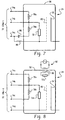
- FIG. 8 Another embodiment of the present invention is shown in FIG. 8 where a getter 72a is installed in the tube and is connected in a loop with an inductor 90, or coil, in a manner known in the art.
- the getter is advantageously placed in the envelope 50 for RF flashing by electromagnetic coupling to an RF source 92 during tube manufacture, prior to assembly in the oil filled tube enclosure.
- a second getter 72b may be installed in the tube in any of the manners described above for field flashing purposes.
- the getters 72, 72a, 72b in the embodiments described above can be automatically flashed by the controller 46 of the diagnostic system 20 in response to monitored operating parameters.
- Typical parameters include signals indicative of gas pressure in the tube, exposure count, number of scans, arcing, temperature, voltage and current of the anode and/or cathode, anode rotation and other desired system operating parameters or ratios of such parameters.
- historical data of these parameters over a predetermined time period may be stored in the systems monitor and memory 44. All of these data can be accessed by the controller 46 and trend analysis compared to predetermined criteria for use in determining the desirability or need to flash the getter in an installed system.
- getters 72, 72a, 72b described above may be partially flashed during the manufacturing process to establish the desired initial vacuum while reserving a portion of getter material for future field service flashing of the getter to re-establish the desired vacuum in a tube that has been in service.
- step 200 the system is initialised and the process starts.
- step 202 sample values of tube performance characteristics and number of exposures etc. are obtained.
- step 203 exposure counts etc. are incremented, and ratios are determined.
- the various values and ratios are stored in memory, as desired.
- step 204 a determination is made as to whether any one of the parameters, or combination of them, is over or under a predetermined threshold or combination of thresholds.
- the particular predetermined threshold for a monitored operating parameter or ratio is advantageously established for each of the specified monitored operating parameters or ratios.
- a predetermined value perhaps 50 ⁇ Torr for a specific tube design
- it is desirable to flash the getter once exposure count exceeds a predetermined threshold, say 60,000 exposures for a specific tube design, then it is desirable to flash the getter.
- a predetermined threshold say 60,000 exposures for a specific tube design
- Similar threshold values may be determined for other monitored operating parameters, including those listed above as well as others. It is to be appreciated that the threshold values described herein are examples of the inventive principles of the invention and are not limitations since different tube designs have different operating parameters and thereby may utilise different threshold values for different tube designs.
- a combination of any number of the monitored parameters may be used to determine the desirability of flashing the getter. For example, if the number of exposures is greater than a predetermined value, say 30,000 exposures, and the arc rate is exceeds a predetermined rate, say 1 arc per 5,000 exposures, then it may be desirable to flash the getter. Such an approach may be desirable when neither of the monitored parameters satisfied its respective individual threshold value for flashing the getter, e.g. 60,000 exposures and 1 arc per 3,000 exposures, but the combination indicates a need to flash the getter.
- step 208 If the monitored operating parameter does not satisfy the predetermined threshold test, indicating that it is desirable to flash the getter, the process progresses to step 208. If the monitored operating parameter satisfies the threshold test, indicating that the monitored value is within the limits that do not require flashing the getter, the answer to step 204 is NO and the process proceeds to step 206.
- step 206 the stored values of the operating parameters are analysed for trend characteristics and compared to predetermined trend values. For example, if tube operating temperature is increasing as the exposure count increases, it may be desirable to flash the getter. If the trend analysis indicates that the trend values are satisfied, indicating that flashing is not required, the process returns to step 202. If the trend values are compared to the predetermined trend values and are not satisfied, indicating that it is desirable to flash the getter, the process proceeds to step 208.
- the scanner systems control 46 determines the amount of getter material to be deposited in response to the received value. For example, if gas pressure is at a predetermined level for a particular tube design, a specified amount of getter is required to be deposited to reduce gas pressure to a desired level. Alternatively, exposure count may dictate when and how much getter material is deposited. For example a typical x-ray tube may have an exposure count service life of 40,000-100,000 exposures. At 50% of tube service life a predetermined portion of the getter may be deposited. At 75% of service life another predetermined portion may be deposited. Each of the other operating parameters, ratios and trend data may be used in a similar manner to determine the amount of getter material to be deposited during a field flash, whether automatically or manually.
- a graph illustrates the mass of preferred getter material, Barium, deposited at a getter flash current of 10 amps over a duration of time.
- the data represented in this graph can be used by the controller to control the amount of getter material deposited during a getter flash.
- Other suitable getter materials to evaporate include titanium and tantalum. It is to be appreciated that other flash currents, time periods and deposit amounts may be used in the present invention.
- a line 94 can be determined from the points of data and may be stored in a look up table or an algorithm as desired.
- step 210 a determination is made as to whether there is any getter material remaining that can be flashed. If the answer is negative the process advances to step 212.
- step 212 the controller 46 does not instruct the tube power supply and control 42 to flash the getter and an instruction is given to actuate an indicator to communicate to the operator that tube operating parameters indicate a decline in tube performance and there is not any getter material to flash to improve the vacuum in the tube. If the determination in step 210 is affirmative, indicating that there is some getter material available to flash, the process proceeds to step 214.
- step 214 the scanner systems control 44 instructs the tube power supply and control 42 to provide the appropriate current to the appropriate conductors 74a, b, c, d to deposit the desired mass of getter material in accordance with FIG. 10 and the requirements of the embodiments described above in FIGS. 3-8. Once the getter material is flashed the process returns to step 202.
- a service diagnostic unit for the scanner system may be included in the input and output device 48.
- the service diagnostic unit may be interfaced by a service technician to either monitor system operating parameters or access stored data from the systems monitor and memory 44. The service technician may then manually flash the getter in the tube rather than automatically having the scanner control system 46 flash the getter.
- an x-ray tube that has been installed in an imaging system, and operating, can have the gas pressure reduced in the envelope by field flashing and/or field actuating a getter to improve getter pumping rate and vacuum.
- Another advantage is that the field flashing and/or actuating of the getter may be accomplished using existing standard wiring configurations, thereby allowing retrofitting of existing installations with the present invention.
- the imaging system controller can determine whether to activate the getter by flashing and/or actuating the getter in the x-ray tube automatically in response to sensed operating characteristics of the tube.
- An additional advantage is that it provides for more accurate control of the rate and amount of getter material deposited during a flash.
- Yet a further advantage is that a single additional getter can be flashed a number of times.
- Another advantage invention is that the number of electrical connections that pass through the vacuum envelope can be minimised.
Landscapes
- Engineering & Computer Science (AREA)
- Manufacturing & Machinery (AREA)
- X-Ray Techniques (AREA)
- Common Detailed Techniques For Electron Tubes Or Discharge Tubes (AREA)
Abstract
Description
- The present invention relates to getters for use in evacuated tube envelopes and is particularly related to an apparatus for use in improving the performance and/or extending the service life of an x-ray tube by selectively improving performance of gas pressure reducing materials in x-ray tubes installed in operating x-ray imaging systems. The present invention finds particular application in conjunction with activating a getter by depositing and/or actuating getter material surface area in x-ray tubes installed in operating imaging systems when improved getter pumping rates are desired. It will be appreciated, however, that the invention is applicable in other applications where it is necessary to improve getter pumping rate in a vacuum tube or envelope.
- The useful life and performance of an x-ray tube are affected by the maintenance of an appropriate vacuum within the tube throughout its operative life. For this reason, creating and maintaining an adequate vacuum over the planned life of the x-ray tube is important. Contaminants that are present in an operating x-ray tube evolve into gases over the life of the tube during normal tube operation. These evolved gases reduce the vacuum level in the tube during its service life.
- Production of a tube or envelope that can maintain an adequate vacuum during operation includes removing residual contaminants left on the tube components. During manufacture the tube components are cleaned and baked in vacuum furnaces. This procedure reduces the amount of surface contaminants available to evolve into gases when the tubes are in service.
- The cleaned x-ray tube components are then assembled and placed within an envelope. The envelope is evacuated using a vacuum pump and sealed from the outside environment. During the pumping process the x-ray tube is heated to further reduce contaminants.
- A getter material typically is located in the vacuum envelope. After the vacuum pump has established a vacuum, the getter material is activated. Depending on the type of material, getters are classified as either (i) evaporable or (ii) non-evaporable e.g, a bulk getter. Activating the getter material may include (i) flashing the getter for an evaporable material or (ii) actuating the getter by raising its temperature for a bulk or non-evaporable getter.
- One method of activating (flashing) an evaporable getter is accomplished by locating a source for an electromagnetic field, usually an RF field, outside the evacuated envelope proximate to the getter coil located inside the envelope. The electromagnetic field is generated and couples with the getter coil, thereby inducing current flow in the coil and heating the getter material in contact with the coil. The heated getter material evaporates and atoms leaving the getter surface are deposited on interior surfaces of the envelope and other internal components. The freshly deposited getter material plated on the interior surfaces absorb additional amounts of residual gas molecules. However, once an x-ray tube is installed in a housing this method of flashing the getter is not easily accomplished. Another method of activating the getter by flashing includes applying electric current directly to the getter material via dedicated terminals. The getter is heated by resistance heating thereby raising the temperature of the getter material to that necessary to evaporate the getter.
- In these types of getters, the getter film produced by flashing reacts with all the residual active gases and, by chemisorption, removes them from the gas phase to further reduce the gas pressure within the evacuated envelope. However, the sorption capacity of the deposited getter material is limited. As sorption capacity is approached, the ability of the getter to sorb additional gas molecules is diminished. The reacted layer includes oxides and additional compounds that include the other evolved and absorbed gases.
- Non-evaporable, or bulk, getters are temperature activated and do not need to be evaporated to be activated. These types of getters are activated by supplying specified electric current levels to the getter causing resistance heating to elevate the getter material to a desired temperature. Once the getter reaches the desired temperature the specific gas molecules are absorbed into the getter. The vacuum in the x-ray tube may be getter pumped to the desired gas pressure level using either a flashed getter or a bulk getter.
- The completed x-ray tube is then mounted into the housing or enclosure that is filled with dielectric oil. Once the oil filled housing containing the x-ray tube is installed in an operative x-ray system, the components continue to evolve gas into the evacuated envelope. The evolved gas is also produced from contaminants that migrate via diffusion through the tube components to their surfaces. These gases react with the getter material that was flashed during the original manufacturing process. As the tube continues to operate and contaminants are absorbed by the getter, sorption capacity of the getter material is reached. The getter material becomes less efficient in removing gas molecules and the gas pressure in the evacuated envelope increases.
- When gas pressures within the evacuated region of the x-ray tube increase, the mean free path between gas molecules is reduced such that a chain reaction is more likely to occur when the gas molecules in the vacuum envelope are ionised by the high electric fields generated during normal tube operation. This chain reaction is called avalanche and is a form of arcing. An arc is an undesired surge of electrical current between two elements which are at a different electrical potential and typically occurs through the gas molecules present in the x-ray tube. In x-ray tubes, this tendency to arc often increases as the tube ages due to such factors as degradation of the vacuum within the tube due to the existence of additional undesired gas molecules. When the x-ray tube arcs, a current on the order of hundreds of amperes can flow between the cathode and the anode. Once an x-ray tube starts to arc an avalanche type effect may occur, sputtering metal and metal atoms as well as ionising the contaminants in the vacuum. In addition, arcing in an x-ray tube used in a Computed Tomography (CT) imaging system contaminates the signal collected at the detectors and affects proper image reconstruction. This may result in an un-usable set of data requiring another CT scan of the patient.
- Arcing typically occurs in the area of the x-ray tube having the highest electric field strength. As such, arcing in an x-ray tube may commonly occur in the same region as where the cathode is supplying the anode with electrons for the production of x-ray emissions. The sputtering of metal from the cathode produced during arcing often lands on the internal surface of the glass envelope in proximity to the cathode. The existence of the metal deposits on the glass envelope can deleteriously affect x-ray tube performance. Sputtering of metal within the envelope may increase as internal pressure increases, even in the absence of an arc.
- Thus, it is desirable to have the ability to decrease the gas pressure to an appropriate level in an x-ray tube that has been in service. However, once the tube is installed in an operative system, access to the tube is restricted such that it is difficult to re-establish an appropriate vacuum in the tube.
- An apparatus in accordance with one embodiment of the present invention includes an evacuated tube envelope and an electrode in the tube envelope. A getter is installed in the tube envelope and is electrically connected to a conductor. The conductor is electrically connected to both of the getter and the electrode. The apparatus includes means for selectively providing electrical energy through the conductor to one of the electrode and the getter.
- In accordance with a more limited aspect of the present invention, the apparatus includes a cathode as the electrode.
- Another limited aspect of the present invention includes at least a diode or inductor as the means for selectively providing electrical energy to the getter.
- In accordance with another aspect of the present invention, an x-ray tube comprises a substantially evacuated envelope. An anode is located within the envelope. A cathode filament is located in the envelope. The x-ray tube further includes at least one getter located within the envelope. At least one conductor is included that is electrically connected to both of the cathode filament and the getter.
- In accordance with a more limited aspect of the invention the x-ray tube includes a plurality of getters within the tube and the apparatus includes means for selectively activating at least one of the plurality of getters.
- In accordance with a yet more limited aspect of the invention, the x-ray tube includes a diode in the means for selectively activating the at least one of the plurality of getters. In an alternate more limited aspect of the invention a capacitor is included in the means for selectively activating the at least one of the plurality of getters. In a yet more limited aspect of the present invention, the diode (or capacitor) is connected in series with the cathode filament.
- In yet another aspect of the present invention, an apparatus for activating a getter includes an enclosed tube having a tube wall. The getter is electrically connected to at least one conductor extending through the tube wall. The apparatus comprises means for providing a signal indicative of tube performance. The apparatus also includes means for selectively activating one of the electrode and the getter in response to the signal indicative of tube performance.
- In accordance with a more limited aspect of the invention, the selective activating means includes a controller in data communication with the signal providing means.
- In a more limited aspect of the invention the signal indicative of tube performance includes a signal indicative of at least one of arc rate, gas pressure, operating cycles, starts, exposures, number of scans, current, voltage and temperature.
- In accordance with another aspect of the present invention, an apparatus for controllably activating a getter in an envelope comprises a pressure measuring device advantageously located to determine a measure of the gas pressure within the envelope. The pressure measuring device provides a signal indicative of a measure of the gas pressure within the envelope. A source of electrical energy is operatively connected to the getter and a controller is controllably connected to both of (i) the pressure measuring device and (ii) the source of electrical energy. The controller activates the source of electrical energy in response to the signal provided by the pressure measuring device.
- In a more limited aspect of the present invention, the controller determines the amount of electrical energy to apply to the getter in response to the signal provided by the pressure measuring device.
- In another limited aspect of the invention, the pressure measuring device is an ionisation gauge that includes an anode and a cathode located within the envelope.
- In accordance with another aspect of the present invention, an apparatus comprises an envelope that is substantially evacuated having a first getter located within the envelope. The first getter has a first end electrically connected to a first terminal extending through the envelope and a second end electrically connected to a second terminal extending through the envelope. A second getter located within the envelope.
- In accordance with a more limited aspect of the invention, the second getter has a first end electrically connected to a third terminal extending through the envelope and a second end electrically connected to at least one of the first and second terminal.
- In accordance with another aspect of the present invention, a method is provided for maintaining a pressure level in an enclosed evacuated electrode tube. The method comprises the steps of providing a signal indicative of tube performance and activating getter material in response to the signal indicative of tube performance.
- In a more limited aspect of the present invention the signal indicative of tube performance includes at least one of arc rate, gas pressure, exposure count, number of scans, operating cycles, starts, current, voltage and temperature.
- In another more limited aspect of the present invention, the step of activating the getter includes the step of evaporating getter material.
- In yet a more limited aspect of the present invention, the method includes the step of determining the amount of getter material to activate prior to the step of activating.
- In accordance with another more limited aspect of the present invention, the step of activating the getter includes the step of controlling the amount of getter material evaporated. And a further limited aspect includes a step of evaporating only a portion of the getter material for a discrete activation step. And yet another limited aspect of the present invention includes the step of determining the amount of getter material remaining.
- In accordance with another limited aspect of the present invention, the method includes the steps of monitoring the signals indicative of tube performance and storing values associated with the monitored signals.
- In accordance with another aspect of the present invention, a method of maintaining a substantial vacuum in an x-ray tube comprises the steps of sensing gas pressure in the tube, providing a signal indicative of the gas pressure and activating the getter material in response to the signal.
- In accordance with yet another aspect of the present invention, an imaging apparatus comprises an x-ray source including an envelope that is substantially evacuated, an anode located within the envelope, and a cathode filament located in the envelope. At least one getter is located within the envelope. Means are provided for activating the getter and the apparatus includes an x-ray detector.
- In accordance with a more limited aspect of the present invention, the apparatus further includes a member with an arcuate surface wherein the x-ray detector comprises a plurality of detectors disposed on the arcuate surface of the member.
- In accordance with another aspect of the present invention, a method is provided for flashing a getter in an x-ray tube in an installed imaging system. The method includes the steps of determining the desirability of activating the getter based upon tube operating characteristics and the step of activating the getter.
- Ways of carrying out the invention will now be described in detail, by way of example, with reference to the accompanying drawings, in which:
- FIG. 1 is a schematic diagram of an x-ray diagnostic system in accordance with the present invention;
- FIG. 2 is a sectional view of an x-ray tube;
- FIGS. 3-8 are schematic illustrations showing different embodiments of the present invention;
- FIG. 9 is a flow diagram of a control process in accordance with the present invention;
- FIG. 10 is a graphical representation of the mass of getter material deposited over time for a given current value during a getter flash; and
- FIG. 11 is a schematic partial sectional view of an x-ray tube mounted in a housing.
-
- With reference to Figure 1, a medical
diagnostic apparatus 20 is used to examine with x-rays a subject (not shown) in anexamination region 22. More specifically, anx-ray tube 24 projects radiation through the examiningregion 22 and on to anx-ray detector assembly 26. In the illustrated CT scanner embodiment, thex-ray detector assembly 26 is disposed on an arcuate surface in aring 28 on agantry 30. The detected x-rays are converted into electrical signals which, in turn, are reconstructed into diagnostic images. - It is also contemplated that x-ray detection systems other than the described CT embodiment may be used with the present invention. For example, the medical diagnostic apparatus can be one that produces projection or shadowgraphic images on x-ray sensitive photographic film. Another alternative x-ray diagnostic apparatus can be a digital x-ray system which generates shadowgraphic x-ray images in single or multiple energies electronically. Yet another apparatus includes fluoroscopic imaging systems. In addition, non-medical x-ray detection systems are also contemplated as well as other medical x-ray medical diagnostic systems.
- The
x-ray detector assembly 26 and a tachometer orangular position encoder 32 for detecting rotation or angular position of thex-ray source 24 are connected with animage reconstruction processor 34. Theimage reconstruction processor 34 utilises conventional convolution and back projection or other reconstruction algorithms as are known in the art. Thereconstruction processor 34 produces an electronic image representation for storage in animage memory 36. A humanreadable display 38, such as a video monitor, produces a diagnostic display of the reconstructed image. Generally, a video processor formats the reconstructed image data into a selected format such as a slice, projection, surface rendering, sculptured volumes and the like. - An alternating current (AC) source of
power 40 is connected to an x-ray tube power supply andcontrol 42. Thex-ray tube 24 is operatively connected to the tube power supply andcontrol 42. - A diagnostic system monitor and
memory 44 is in data communication with a plurality of components of thediagnostic apparatus 20 to monitor and store desired performance characteristics to provide signals indicative of system performance. Some of the signals that are monitored are indicative of, gas pressure in the x-ray tube, arc rate, operating cycles, exposure count, number of scans, anode and cathode current and voltage, temperature, anode and cathode voltage balance, anode rotation, and a number of other desirable operating parameters known in the art. An example of a suitable monitoring system is described in U.S. Patent Number 4,853,946 to Elliott et al., entitled "Diagnostic Service System for CT Scanners" which is incorporated herein by reference. The systems monitor andmemory 44 is in data communication with the tube power supply andcontrol 42 and ascanner systems control 46. The scanner systems control 46 is a suitable computer or microcomputer with all required systems and memory for operating thediagnostic device 20. The systems control 46 includes sufficient memory capacity to store data for controlling various scanner and tube operations in look up tables or as algorithms as desired. - The scanner systems control 46 is controllably connected with and in data communication with the operative components of the medical
diagnostic apparatus 20 in a manner known in the art. Input andoutput devices 48 are connected to thescanner systems control 46. Input andoutput devices 48 may include a field service diagnostics device, an operators console, communications devices and modems, printers, monitors and other devices as appropriate. The systems control 46 manages and controls the operation of thediagnostic apparatus 20 in response to (i) inputs received from the monitored components of theapparatus 20, (ii) system operators and (iii) field service technicians via the input andoutput devices 48. - Referring now to FIG. 2, the
x-ray tube 24 includes an evacuatedenvelope 50 in which ananode 52 is rotatably mounted. Theenvelope 50 is preferably made of glass or metal and may be constructed of other suitable materials. Theanode 52 is connected to ashaft 54 which is connected to aninduction motor 56. Themotor 56 includesrotor windings 58 and associated bearings (not shown) are mounted in aneck portion 60 of the evacuatedenvelope 50. Therotor windings 58 are electromagnetically coupled with a main stator winding 62 on the outside of theneck portion 60. Theanode 52 is rotated at high speed during tube operation. It is to be appreciated that the present invention is also applicable to stationary anode x-ray tubes and other electrode vacuum tubes. - A
cathode 64 is supported in theenvelope 50 on acathode support assembly 66. Thecathode support assembly 66 is fixedly attached a cathode conductor feed through andheader assembly 68 that is ultimately secured to theenvelope 50 with a vacuum tight seal (not shown). Agetter shield 70 is joined to theheader assembly 68. Agetter 72 is attached to the feed through andheader assembly 68. -
Cathode conductors 74a, b, c are electrically connected to feed throughterminals 76 that extend through the header assembly and are connected to a plurality of conductors. Since the electrical interconnections between terminals and conductors are not apparent in this figure, the arrangement of the cathode conductors in FIG. 2 are not necessarily indicative of a specific embodiment of the present invention but is representative of an example of a physical arrangement for feeding conductors through a header to components within theenvelope 50. Actual circuit connections for the cathode conductors and getters to the terminals 106 a-d according to the present invention are described and illustrated in accordance with FIGS. 3 - 8 below. Like numerals are used for similar elements in the different embodiments of the present invention. - Referring briefly to FIG. 11, typically, the
x-ray tube 24, of FIG. 2, is mounted within an oil filledhousing 100 in a manner known in the art. The housing is equipped with the necessaryhigh voltage connectors cathode terminals 106a-d andanode terminals 108a-d to provide electrical power to theenclosed x-ray tube 24. It is to be appreciated that, while FIG. 11 illustrates four terminals in thehigh voltage connectors - Turning now to FIG. 3, one embodiment of the present invention is illustrated. Four
conductors 74 a,b,c,d, exit theenvelope 50.Conductor 74a is connected to a first end of afirst cathode filament 78a.Conductor 74b is connected to (i) a second end of thecathode filament 78a, (ii) a first end of asecond cathode filament 78b, and (iii) a first end ofgetter 72.Conductor 74c is connected to a second end of thesecond cathode filament 78b. Theconductor 74d is connected to a second end ofgetter 72 and to acathode grid cup 80. - Presently designed and installed imaging systems have high voltage connectors with a fixed number of conductor terminals or contacts, e.g. a four (4) pin connector. Flashing the
getter 72 in the field using an x-ray tube according to the present invention can be accomplished in presently designed imaging systems by removal of the four pin high voltage connector (not shown) on the cathode side of the x-ray tube housing and having the service technician apply the desired voltage and current toterminals envelope 50. The current flow in the getter conductors heats the getter material in contact with the conductors. The heated getter material evaporates and atoms leaving the getter surface are deposited on interior surfaces of the envelope and other internal components. The freshly deposited getter material plated on the interior surfaces absorb additional amounts of residual gas molecules. The tube may remain within the oil filled tube housing during this process. Thus, the flashed getter is activated since the reacted layer is now plated over with fresh material. Alternatively, a bulk getter may be actuated by having electric current applied to it for a predetermined period of time. The bulk getter thereby has its temperature raised to that required to absorb specific gas molecules. The getter is actuated for the time period required to pump a sufficient number of the evolved gas molecules and reduce the gas pressure in the tube. - It also is contemplated that an x-ray tube and associated housing be provided such that a getter has dedicated conductors. The getter conductors are advantageously connected to permit flashing of the getter in the field without requiring the removal of the high voltage connection. Such getter conductors could be easily accessible on new tube and housing designs to a service technician or permenanently connected to a proper source of electrical energy that may be manually or automatically controlled to activate the getter by flashing or actuating.
- Another embodiment of the present invention, as seen in FIG. 4, includes
diodes diode 82a is connected to theconductor 74a. The anode of thediode 82a is connected to a first end of agetter 72a. A second end of thegetter 72a is connected to theconductor 74b. The anode of thediode 82b is connected to theconductor 74a and the cathode of thediode 82b is connected to thecathode filament 78a. The other end of thecathode filament 78a is connected to theconductor 74b. Asecond getter 72b is connected to theconductor 74b and to theconductor 74d. Asecond cathode filament 78b is connected to theconductor 74b and theconductor 74c. Thecathode grid cup 80 is connected to theconductor 74d. - With continuing reference to FIG. 4, under normal tube operation, the
cathode filament 78a is energised usingconductors diode 82b permits the desired and appropriately polarised DC current to flow fromconductor 74a through thecathode filament 78a. Thegetter 72a is flashed by reversing the DC polarity on theconductors diode 82a permits flow of appropriate current fromconductor 74b through thegetter 72a andconductor 74a. This embodiment of the present invention has five conductors exiting thetube envelope 50 but still has only four conductor terminals for the four pin high voltage connector (not shown) to be connected with the fourconductors 74a, b, c, d. It is to be appreciated that the diodes may be located within theenvelope 50 thereby having only four conductors exiting thetube envelope 50. - Referring now to FIG. 5, another embodiment of the present invention is shown.
Diodes diode 82a is connected to theconductor 74a. The anode of thediode 82a is connected to a first end of agetter 72a. A second end of thegetter 72a is connected to theconductor 74b. The anode of thediode 82b is connected to theconductor 74a and its cathode is connected to thecathode filament 78a. The other end of thecathode filament 78a is connected to theconductor 74b. Asecond getter 72b is connected to theconductor 74b and to the anode of a diode 84a. The cathode of the diode 84a is connected to theconductor 74c. Asecond cathode filament 78b is connected to theconductor 74b and the cathode of adiode 84b. The anode of thediode 84b is connected toconductor 74c. Thecathode grid cup 80 is connected to theconductor 74d. This embodiment of the present invention has six conductors exiting thetube envelope 50 but still has only four conductor terminals for the four pin high voltage connector (not shown) to be connected with the fourconductors 74a, b, c, d. It is to be appreciated that the diodes may be located within theenvelope 50 thereby having only four conductors exiting thetube envelope 50. - This arrangement, illustrated in FIG. 5, permits using the components of the x-ray tube to monitor gas pressure in the evacuated envelope with known ionisation gauge techniques. Basically electrons are accelerated between the cathode and the grid, but cannot reach the anode since it is connected at a negative potential. Some electrons, however, collide with gas molecules in the tube and ionise them, leaving them positively charged. The positively charged gas molecules then go to the anode and the anode current produced provides a measure indicative of the number of gas molecules present in the evacuated envelope.
- In FIG. 6, another embodiment of the present invention is shown that has a
single cathode filament 78 attached between theconductors single getter 72 is attached between theconductors cathode grid cup 80 is connected to theconductor 74c. - Turning now to FIG. 7, a preferred embodiment of the present invention is described. The
x-ray tube 24 is one that applies alternating current (AC) to thecathode filaments conductors capacitor 86 is connected between theconductor 74c and thecathode filament 78b. The other end of thecathode filament 78b is connected toconductor 74b. Thecathode filament 78a is connected between theconductors getter 72 is connected to theconductor 74b and the other end is connected to one terminal of aninductor 88. The other end of theinductor 88 is connected to theconductor 74c. Thecathode grid cup 80 is connected to theinductor 88 and thegetter 72. - The
filaments conductor inductor 88 resists the flow of AC current through thegetter 72 to a level insufficient to flash the getter. Thecapacitor 86 is advantageously selected to permit flow of sufficient AC current through thecathode filament 78b for tube operation and to effectively limit DC current in the filament during getter flashing. To flash thegetter 72, DC current is applied by an appropriate source to theconductors - Another embodiment of the present invention is shown in FIG. 8 where a
getter 72a is installed in the tube and is connected in a loop with aninductor 90, or coil, in a manner known in the art. The getter is advantageously placed in theenvelope 50 for RF flashing by electromagnetic coupling to anRF source 92 during tube manufacture, prior to assembly in the oil filled tube enclosure. Asecond getter 72b may be installed in the tube in any of the manners described above for field flashing purposes. - The
getters controller 46 of thediagnostic system 20 in response to monitored operating parameters. Typical parameters include signals indicative of gas pressure in the tube, exposure count, number of scans, arcing, temperature, voltage and current of the anode and/or cathode, anode rotation and other desired system operating parameters or ratios of such parameters. In addition, historical data of these parameters over a predetermined time period may be stored in the systems monitor andmemory 44. All of these data can be accessed by thecontroller 46 and trend analysis compared to predetermined criteria for use in determining the desirability or need to flash the getter in an installed system. - In addition, the
getters - Referring now to FIG. 9, a flow chart of a suitable control process for the present invention to automatically flash a getter installed in the field in response to monitored operating parameters is shown. Beginning in
step 200, the system is initialised and the process starts. Instep 202, sample values of tube performance characteristics and number of exposures etc. are obtained. Next, instep 203, exposure counts etc. are incremented, and ratios are determined. The various values and ratios are stored in memory, as desired. The process then proceeds to step 204 where a determination is made as to whether any one of the parameters, or combination of them, is over or under a predetermined threshold or combination of thresholds. The particular predetermined threshold for a monitored operating parameter or ratio is advantageously established for each of the specified monitored operating parameters or ratios. For example, if gas pressure within the tube is determined to be greater than a predetermined value, perhaps 50 µTorr for a specific tube design, then it is desirable to flash the getter. Alternatively, once exposure count exceeds a predetermined threshold, say 60,000 exposures for a specific tube design, then it is desirable to flash the getter. Similar threshold values may be determined for other monitored operating parameters, including those listed above as well as others. It is to be appreciated that the threshold values described herein are examples of the inventive principles of the invention and are not limitations since different tube designs have different operating parameters and thereby may utilise different threshold values for different tube designs. - In addition, a combination of any number of the monitored parameters may be used to determine the desirability of flashing the getter. For example, if the number of exposures is greater than a predetermined value, say 30,000 exposures, and the arc rate is exceeds a predetermined rate, say 1 arc per 5,000 exposures, then it may be desirable to flash the getter. Such an approach may be desirable when neither of the monitored parameters satisfied its respective individual threshold value for flashing the getter, e.g. 60,000 exposures and 1 arc per 3,000 exposures, but the combination indicates a need to flash the getter.
- If the monitored operating parameter does not satisfy the predetermined threshold test, indicating that it is desirable to flash the getter, the process progresses to step 208. If the monitored operating parameter satisfies the threshold test, indicating that the monitored value is within the limits that do not require flashing the getter, the answer to step 204 is NO and the process proceeds to step 206.
- In
step 206, the stored values of the operating parameters are analysed for trend characteristics and compared to predetermined trend values. For example, if tube operating temperature is increasing as the exposure count increases, it may be desirable to flash the getter. If the trend analysis indicates that the trend values are satisfied, indicating that flashing is not required, the process returns to step 202. If the trend values are compared to the predetermined trend values and are not satisfied, indicating that it is desirable to flash the getter, the process proceeds to step 208. - In
step 208, the scanner systems control 46 determines the amount of getter material to be deposited in response to the received value. For example, if gas pressure is at a predetermined level for a particular tube design, a specified amount of getter is required to be deposited to reduce gas pressure to a desired level. Alternatively, exposure count may dictate when and how much getter material is deposited. For example a typical x-ray tube may have an exposure count service life of 40,000-100,000 exposures. At 50% of tube service life a predetermined portion of the getter may be deposited. At 75% of service life another predetermined portion may be deposited. Each of the other operating parameters, ratios and trend data may be used in a similar manner to determine the amount of getter material to be deposited during a field flash, whether automatically or manually. - Referring briefly to FIG 10, a graph illustrates the mass of preferred getter material, Barium, deposited at a getter flash current of 10 amps over a duration of time. The data represented in this graph can be used by the controller to control the amount of getter material deposited during a getter flash. Other suitable getter materials to evaporate include titanium and tantalum. It is to be appreciated that other flash currents, time periods and deposit amounts may be used in the present invention. A
line 94 can be determined from the points of data and may be stored in a look up table or an algorithm as desired. - Returning again to FIG. 9, once the amount of getter material to be deposited is determined in
step 208, using the data in FIG. 10, the process progresses to step 210 where a determination is made as to whether there is any getter material remaining that can be flashed. If the answer is negative the process advances to step 212. Instep 212, thecontroller 46 does not instruct the tube power supply andcontrol 42 to flash the getter and an instruction is given to actuate an indicator to communicate to the operator that tube operating parameters indicate a decline in tube performance and there is not any getter material to flash to improve the vacuum in the tube. If the determination instep 210 is affirmative, indicating that there is some getter material available to flash, the process proceeds to step 214. - In
step 214, the scanner systems control 44 instructs the tube power supply andcontrol 42 to provide the appropriate current to theappropriate conductors 74a, b, c, d to deposit the desired mass of getter material in accordance with FIG. 10 and the requirements of the embodiments described above in FIGS. 3-8. Once the getter material is flashed the process returns to step 202. - It is also contemplated that a service diagnostic unit for the scanner system may be included in the input and
output device 48. The service diagnostic unit may be interfaced by a service technician to either monitor system operating parameters or access stored data from the systems monitor andmemory 44. The service technician may then manually flash the getter in the tube rather than automatically having thescanner control system 46 flash the getter. - In addition, electrical power can be applied to the cathode filaments and getters using a fibre optic controlled switching apparatus. A suitable example of a fibre optic switching apparatus and method for use in the present invention is disclosed in U.S. Patent Number 4,685,118 issued to Furbee et al., which is frilly incorporated herein by this reference.
- While a particular feature of the invention may have been described above with respect to only one of the illustrated embodiments, such features may be combined with one or more other features of other embodiments, as may be desired and advantageous for any given particular application.
- From the above description of the invention, those skilled in the art will perceive improvements, changes and modification. Such improvements, changes and modification within the skill of the art are intended to be covered by the appended claims.
- One advantage of the described embodiments is that an x-ray tube that has been installed in an imaging system, and operating, can have the gas pressure reduced in the envelope by field flashing and/or field actuating a getter to improve getter pumping rate and vacuum.
- Another advantage is that the field flashing and/or actuating of the getter may be accomplished using existing standard wiring configurations, thereby allowing retrofitting of existing installations with the present invention.
- Yet a further advantage is that the imaging system controller can determine whether to activate the getter by flashing and/or actuating the getter in the x-ray tube automatically in response to sensed operating characteristics of the tube.
- An additional advantage is that it provides for more accurate control of the rate and amount of getter material deposited during a flash.
- Yet a further advantage is that a single additional getter can be flashed a number of times.
- Another advantage invention is that the number of electrical connections that pass through the vacuum envelope can be minimised.
Claims (16)
- An apparatus for use in an evacuated tube envelope (50), the apparatus comprising: an electrode (78, 78a, 78b) in the tube envelope (50); a getter (72, 72a, 72b) in the tube envelope; a conductor (74a, 74b, 74c) electrically connected to both of the electrode and the getter; and means for selectively providing electrical energy through the conductor to one of the electrode and the getter.
- Apparatus as claimed in claim 1, further including a second conductor (74a-74d) electrically connected to the electrode (78, 78a, 78b) and a third conductor (74a-74d) electrically connected to the getter (72, 72a, 72b).
- Apparatus as claimed in claim 1 or claim 2, wherein the electrode (78, 78a, 78b) is a cathode.
- Apparatus as claimed in any one of claims 1 to 3, wherein the means for selectively providing electrical energy includes a diode (82a, 82b) electrically connected to the getter (72, 72a, 72b).
- Apparatus as claimed in any one of claims 1 to 3, wherein the means for selectively providing electrical energy includes an inductor (90) electrically connected to the getter.
- Apparatus as claimed in any one of claims 1 to 5, wherein the evacuated tube envelope is an x-ray tube.
- Apparatus as claimed in any one of claims 1 to 6, including a plurality of getters wherein at least one of the getters is activated by flashing.
- Apparatus as claimed in claim 7, including means for selectively providing electrical energy to at least one of the plurality of getters.
- Apparatus as claimed in claim 8, wherein the means for selectively providing electrical energy to the at least one of the plurality of getters includes a diode.
- Apparatus as claimed in claim 8, wherein the means for selectively providing electrical energy to the at least one of the plurality of getters includes an inductor.
- Apparatus as claimed in any one of claims 1 to 10, wherein the means for selectively providing electrical energy includes a fiber optic transmission path.
- Apparatus as claimed in any one of claims 1 to 11, including: means (44) for providing a signal indicative of tube performance; and means for activating the getter in response to the signal indicative of tube performance.
- Apparatus as claimed in claim 12, wherein the means for activating includes a controller in data communication with the means for providing a signal.
- Apparatus as claimed in claim 12, wherein the signal indicative of tube performance includes a signal indicative of at least one of arc rate, gas pressure, operating cycles, starts, exposures, number of scans, current, voltage and temperature.
- Apparatus as claimed in any one of claims 12 to 14, wherein the means for activating includes a diode.
- Apparatus as claimed in any one of claims 12 to 14, wherein the means for activating includes a capacitor.
Applications Claiming Priority (2)
| Application Number | Priority Date | Filing Date | Title |
|---|---|---|---|
| US248599 | 1988-09-26 | ||
| US09/248,599 US6192106B1 (en) | 1999-02-11 | 1999-02-11 | Field service flashable getter for x-ray tubes |
Publications (1)
| Publication Number | Publication Date |
|---|---|
| EP1028450A1 true EP1028450A1 (en) | 2000-08-16 |
Family
ID=22939811
Family Applications (1)
| Application Number | Title | Priority Date | Filing Date |
|---|---|---|---|
| EP00300934A Withdrawn EP1028450A1 (en) | 1999-02-11 | 2000-02-07 | Getter for use in evacuated tube envelopes |
Country Status (3)
| Country | Link |
|---|---|
| US (1) | US6192106B1 (en) |
| EP (1) | EP1028450A1 (en) |
| JP (1) | JP2000294179A (en) |
Cited By (1)
| Publication number | Priority date | Publication date | Assignee | Title |
|---|---|---|---|---|
| WO2025233814A1 (en) * | 2024-05-07 | 2025-11-13 | Nano-X Imaging Ltd | System and method for increasing operational lifetime of a field emission vacuum tube |
Families Citing this family (6)
| Publication number | Priority date | Publication date | Assignee | Title |
|---|---|---|---|---|
| JP4541536B2 (en) * | 2000-12-25 | 2010-09-08 | エスアイアイ・ナノテクノロジー株式会社 | Discharge detection circuit. |
| US6570959B1 (en) | 2001-07-18 | 2003-05-27 | Koninklijke Philips Electronics N.V. | X-ray tube metal frame gettering device |
| DE10314538A1 (en) * | 2003-03-31 | 2004-10-28 | Siemens Ag | X-ray tube pressure monitoring method in which the pressure inside the tube is measured, based on measurements of heating and tube currents and their comparison with calibration values, to predict remaining tube service life |
| KR101151859B1 (en) * | 2010-03-26 | 2012-05-31 | 주식회사엑스엘 | X-ray Tube Having Non-evaporable Getter |
| US11751317B2 (en) * | 2019-03-01 | 2023-09-05 | Shimadzu Corporation | X-ray generating device, and diagnostic device and diagnostic method therefor |
| US11701072B2 (en) * | 2021-04-02 | 2023-07-18 | AlxSCAN, Inc. | Modular X-ray source and method of X-ray source tube replacement for motion compensated tomosynthesis imaging system |
Citations (5)
| Publication number | Priority date | Publication date | Assignee | Title |
|---|---|---|---|---|
| GB546846A (en) * | 1940-07-25 | 1942-07-31 | Hazeltine Corp | Improvements in cathode-ray tubes |
| US2668253A (en) * | 1950-07-06 | 1954-02-02 | American Television Inc | Getter for electron discharge devices |
| US2988657A (en) * | 1958-08-02 | 1961-06-13 | Philips Corp | Ion pump |
| JPS60172154A (en) * | 1984-02-17 | 1985-09-05 | Hitachi Ltd | X-ray tube |
| JPH08153460A (en) * | 1994-11-29 | 1996-06-11 | Canon Inc | Electron source and image forming apparatus using the same |
Family Cites Families (9)
| Publication number | Priority date | Publication date | Assignee | Title |
|---|---|---|---|---|
| US4685118A (en) | 1983-11-10 | 1987-08-04 | Picker International, Inc. | X-ray tube electron beam switching and biasing method and apparatus |
| US4853946A (en) | 1986-11-14 | 1989-08-01 | Picker International, Inc. | Diagonostic service system for CT scanners |
| US5438605A (en) | 1992-01-06 | 1995-08-01 | Picker International, Inc. | Ring tube x-ray source with active vacuum pumping |
| US5734226A (en) | 1992-08-12 | 1998-03-31 | Micron Technology, Inc. | Wire-bonded getters useful in evacuated displays |
| US5453659A (en) | 1994-06-10 | 1995-09-26 | Texas Instruments Incorporated | Anode plate for flat panel display having integrated getter |
| US5685963A (en) | 1994-10-31 | 1997-11-11 | Saes Pure Gas, Inc. | In situ getter pump system and method |
| US5509045A (en) | 1995-02-09 | 1996-04-16 | Picker International, Inc. | X-ray tube having a getter shield and method |
| US5838761A (en) | 1996-05-06 | 1998-11-17 | Siemens Aktiengesellschaft | X-ray tube with getter |
| US6044129A (en) * | 1997-11-21 | 2000-03-28 | Picker International, Inc. | Gas overload and metalization prevention for x-ray tubes |
-
1999
- 1999-02-11 US US09/248,599 patent/US6192106B1/en not_active Expired - Fee Related
-
2000
- 2000-02-07 EP EP00300934A patent/EP1028450A1/en not_active Withdrawn
- 2000-02-14 JP JP2000077243A patent/JP2000294179A/en active Pending
Patent Citations (5)
| Publication number | Priority date | Publication date | Assignee | Title |
|---|---|---|---|---|
| GB546846A (en) * | 1940-07-25 | 1942-07-31 | Hazeltine Corp | Improvements in cathode-ray tubes |
| US2668253A (en) * | 1950-07-06 | 1954-02-02 | American Television Inc | Getter for electron discharge devices |
| US2988657A (en) * | 1958-08-02 | 1961-06-13 | Philips Corp | Ion pump |
| JPS60172154A (en) * | 1984-02-17 | 1985-09-05 | Hitachi Ltd | X-ray tube |
| JPH08153460A (en) * | 1994-11-29 | 1996-06-11 | Canon Inc | Electron source and image forming apparatus using the same |
Non-Patent Citations (2)
| Title |
|---|
| PATENT ABSTRACTS OF JAPAN vol. 010, no. 008 (E - 373) 14 January 1986 (1986-01-14) * |
| PATENT ABSTRACTS OF JAPAN vol. 1996, no. 10 31 October 1996 (1996-10-31) * |
Cited By (1)
| Publication number | Priority date | Publication date | Assignee | Title |
|---|---|---|---|---|
| WO2025233814A1 (en) * | 2024-05-07 | 2025-11-13 | Nano-X Imaging Ltd | System and method for increasing operational lifetime of a field emission vacuum tube |
Also Published As
| Publication number | Publication date |
|---|---|
| JP2000294179A (en) | 2000-10-20 |
| US6192106B1 (en) | 2001-02-20 |
Similar Documents
| Publication | Publication Date | Title |
|---|---|---|
| JP6326562B2 (en) | X-ray system | |
| US6192106B1 (en) | Field service flashable getter for x-ray tubes | |
| WO2013131628A1 (en) | Compact x-ray sources for moderate loading with x-ray tube with carbon nanotube cathode | |
| EP0578454A1 (en) | Mammography method and mammography X-ray tube | |
| EP0726592B1 (en) | X-ray tube having a getter shield and method | |
| US7197115B2 (en) | Cantilever and straddle x-ray tube configurations for a rotating anode with vacuum transition chambers | |
| CN110946606B (en) | Tomography apparatus and method for operating the same | |
| AU7337494A (en) | Method and system for extending the service life of an x-ray tube | |
| JP3983982B2 (en) | Dental X-ray machine | |
| JP2005038825A (en) | Microfocus X-ray tube and X-ray apparatus using the same | |
| US7580507B2 (en) | Liquid flow sensor fox x-ray tubes | |
| JPH0673292B2 (en) | X-ray tube enclosure with resistive coating | |
| CN114305480B (en) | Oral cavity X-ray shooting device and control method thereof | |
| DE19618122C2 (en) | X-ray | |
| JP3006668B2 (en) | X-ray equipment | |
| JP2022134597A (en) | Radiation tube and radiation source | |
| US20250082296A1 (en) | Medical image capturing system | |
| JP2014067665A (en) | X-ray tube device and x-ray diagnostic device using the same | |
| JP4945020B2 (en) | X-ray tube device | |
| JP7036675B2 (en) | BA type ionization vacuum gauge and its sensitivity abnormality detection method, and pressure measurement method using BA type ionization vacuum gauge | |
| JPH10335093A (en) | X-ray tube device | |
| US20200055150A1 (en) | Ultra high vacuum laser welder system | |
| JP2026076599A (en) | X-ray tube apparatus and X-ray apparatus | |
| WO2025201930A1 (en) | Method for performing kilovoltage peak switching computed tomography, computer program, computed tomography system, and use of a radiation filter | |
| CN112602381A (en) | X-ray device |
Legal Events
| Date | Code | Title | Description |
|---|---|---|---|
| PUAI | Public reference made under article 153(3) epc to a published international application that has entered the european phase |
Free format text: ORIGINAL CODE: 0009012 |
|
| AK | Designated contracting states |
Kind code of ref document: A1 Designated state(s): AT BE CH LI |
|
| AX | Request for extension of the european patent |
Free format text: AL;LT;LV;MK;RO;SI |
|
| 17P | Request for examination filed |
Effective date: 20010214 |
|
| AKX | Designation fees paid |
Free format text: AT BE CH LI |
|
| RBV | Designated contracting states (corrected) |
Designated state(s): DE FR NL |
|
| RAP1 | Party data changed (applicant data changed or rights of an application transferred) |
Owner name: PHILIPS MEDICAL SYSTEMS (CLEVELAND), INC. |
|
| RAP1 | Party data changed (applicant data changed or rights of an application transferred) |
Owner name: KONINKLIJKE PHILIPS ELECTRONICS N.V. |
|
| 17Q | First examination report despatched |
Effective date: 20031121 |
|
| STAA | Information on the status of an ep patent application or granted ep patent |
Free format text: STATUS: THE APPLICATION IS DEEMED TO BE WITHDRAWN |
|
| 18D | Application deemed to be withdrawn |
Effective date: 20040402 |