EP1028389B1 - Arithmetic unit for image transformation - Google Patents
Arithmetic unit for image transformation Download PDFInfo
- Publication number
- EP1028389B1 EP1028389B1 EP00100376A EP00100376A EP1028389B1 EP 1028389 B1 EP1028389 B1 EP 1028389B1 EP 00100376 A EP00100376 A EP 00100376A EP 00100376 A EP00100376 A EP 00100376A EP 1028389 B1 EP1028389 B1 EP 1028389B1
- Authority
- EP
- European Patent Office
- Prior art keywords
- image
- fisheye
- coordinates
- arithmetic unit
- coordinate calculating
- Prior art date
- Legal status (The legal status is an assumption and is not a legal conclusion. Google has not performed a legal analysis and makes no representation as to the accuracy of the status listed.)
- Expired - Lifetime
Links
Images



Classifications
-
- G—PHYSICS
- G06—COMPUTING OR CALCULATING; COUNTING
- G06T—IMAGE DATA PROCESSING OR GENERATION, IN GENERAL
- G06T3/00—Geometric image transformations in the plane of the image
- G06T3/04—Context-preserving transformations, e.g. by using an importance map
- G06T3/047—Fisheye or wide-angle transformations
Definitions
- the present invention relates to an arithmetic unit for image transformation and a monitoring system. More particularly, the invention relates to an arithmetic unit for image transformation for transforming an image obtained by using a fisheye lens into a plane image for display and a monitoring system having the arithmetic unit.
- An arithmetic unit for image transformation is used in, for example, a monitoring system using a monitoring camera.
- the operator monitors the state in a space (for example, shop) in which the monitoring camera is installed, by watching images from the monitoring camera displayed on a monitor provided for the monitoring system.
- a lens attached to the camera is an ordinary standard lens
- the space can be monitored only within the range of the angle of view of the standard lens.
- it is necessary to provide a mechanism for properly changing the orientation of the camera.
- the cost increases and the camera has to be remote controlled. It consequently becomes hard for the operator to handle it.
- the system transforms a circular image obtained by using the fisheye lens into an image produced by a normal image pickup lens (for example, standard lens) by an arithmetic process and a plane image seen from an arbitrary view point can be obtained.
- a normal image pickup lens for example, standard lens
- plane image data can be obtained at real time rates only by software. In most of the cases, it takes long time for a communicating process, operation as a human interface, and the like in a terminal device connected to a network. It is therefore preferable to realize a part in which the same process is repeated in an image transforming process, by hardware.
- the projecting method (stereoscopic projection, equidistant projection, orthogonal projection, or the like) of projecting a fisheye lens image onto an image pickup device (such as CCD) provided for the camera is determined at the time of designing, by executing arithmetic computations according to mathematical expressions by hardware, the image can be transformed to a plane image.
- the invention has been achieved in consideration of the actual condition of the conventional technique and it is an object of the invention to provide an arithmetic unit for image transformation capable of providing inexpensive hardware for transforming a fisheye image obtained by using a fisheye lens into a plane image for display.
- an arithmetic unit for image transformation according to the appended claims 1 and 2 is provided, said unit transforming a fisheye image obtained by using a fisheye lens into a plane image for display.
- a monitoring system is characterized by comprising the arithmetic unit for image transformation.
- the arithmetic unit can be constructed by combining simple arithmetic circuits and the cost of the hardware part in the arithmetic unit for image transformation can be reduced, so that an inexpensive monitoring system can be provided.
- the coordinate system will be set as follows.
- an (X, Y, Z) coordinate space in which the position of a fisheye lens is the origin and the direction of the optical axis is the Z axis is set.
- the azimuth ( ⁇ ) and the zenithal angle ( ⁇ ) are set as parameters indicating the position of the object seen from the origin.
- an image pickup device such as CCD
- CCD image pickup device
- a plane image to be obtained is shown by an (u, v) coordinate system in Fig. 1. It is assumed that the center (origin) of the (u, v) coordinate system is in the position apart from the origin of the (X, Y, Z) coordinate system by distance 1 and is in contact with the hemispherical face as the imaginary object face.
- the plane expressed by the (u, v) coordinate system is made to correspond to pixels of a display image on a monitor.
- the angle between the u axis of the coordinate system and the (X, Y) plane that is, the angle between the u axis and an intersecting line of a plane which passes the origin of the (u, v) coordinate system and is parallel with the (X, Y) plane is set as ( ⁇ ).
- a plane image (fisheye image) obtained through the fisheye lens is expressed by a (p, q) coordinate system as shown in Fig. 1. It is assumed that the (p, q) coordinate system is parallel to the (X, Y) plane and has the origin on the Z axis.
- An image is transformed as follows.
- the projecting position on the image pickup face (p, q coordinates) of a point (u, v coordinates) on a plane image is obtained by arithmetic operation.
- data of the plane image to be obtained can be generated.
- Information of the view points ( ⁇ , ⁇ , ⁇ ) and the scale factor (zoom ratio) as the size of the plane image is information inputted by the operator through a keyboard, pointing device, or the like and is obtained and set in advance as data for calculation by a higher-order arithmetic processing unit.
- Necessary parameters are, as shown in Figs. 1 and 2, (X 0 , Y 0 , Z 0 ) indicative of the center (origin) of a plane image and change amounts ⁇ ux, ⁇ vx, ⁇ uy, ⁇ vy, ⁇ uz, ⁇ vz in the respective axes of the (X, Y, Z) coordinates when a point is moved in the respective directions on the (u, v) coordinate system by an amount of one pixel (corresponding to one pixel on the monitor screen).
- the parameters can be easily obtained from the angle information ( ⁇ , ⁇ , ⁇ ) of the view point and the magnification of the image.
- the calculating procedure is performed by, broadly, two steps of first and second steps.
- the distance between the origin O of the (X, Y, Z) coordinate system and the point P' expressed by the coordinates (X 2 , Y 2 , Z 2 ) is 1.
- the distance between the origin (X 0 , Y 0 , Z 0 ) of the (u, v) coordinate system and the point P' expressed by the coordinates (X 2 , Y 2 , Z 2 ) is 2 sin ( 1 / 2 arctg u 2 1 +v 2 1 ).
- h can be expressed as a function determined by Z 2 .
- h F(cos -1 (Z 2 ))
- the coefficient k 2 of the equation (2) can be derived as a function of Z 2 .
- a lookup table for obtaining the coefficient k 2 from the value of Z 2 in accordance with the equation (3) is generated.
- calculation is limited to addition and multiplication, and the other functions are obtained from the lookup table.
- the calculation in the second step is limited to multiplication and the other calculation of functions and the like is handled by referring to the lookup table.
- a simple arithmetic circuit logic circuit such as an adder
- the circuit scale of the part of the complicated function calculation is suppressed by using the lookup table.
- a fisheye lens of a different projecting method can be dealt with easily, moreover, by the same arithmetic circuit.
- the configuration relates to an example of a substrate which is configured for a computer system having a PCI (Peripheral Component Interconnect) bus.
- PCI Peripheral Component Interconnect
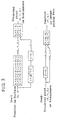
- a fisheye lens 2 is attached to a CCD camera 1 and image information obtained by the CCD camera 1 is sent to a PCI bus substrate 3 and subjected to processes for image transformation.
- the PCI bus substrate 3 comprises: a camera interface 30 for obtaining fisheye image data from a CCD provided for the CCD camera 1; a frame memory 31 for storing fisheye image data of one frame; an interpolation computing unit 32 for executing an interpolating computation on the basis of the calculation result of an operation part 40; an FIFO memory 33; a capture control unit 34 for controlling capture of the fisheye image data to the frame memory 31; the operation part 40 (part surrounded by a broken line) having the configuration which characterizes the invention; and a PCI bus interface 39 for sending plane image data obtained by the coordinate transformation.
- the operation part 40 comprises a first coordinate calculating unit 35, a second coordinate calculating unit 36, a first lookup table 37 connected to the first coordinate calculating unit 35, and a second lookup table 38 connected to the second coordinate calculating unit 36. Further description will be given in relation to the coordinate transforming procedure.
- the first coordinate calculating unit 35 is a part of executing the calculation of the first step shown in Fig. 3 and can obtain the first projection coordinates (X 2 , Y 2 , Z 2 ) on the hemispherical face from the (u, v) coordinates in the plane image.
- the first lookup table 37 is a table for obtaining the correction coefficient k 1 from the distance L.
- the second coordinate calculating unit 36 is a part of executing the calculation of the second step in Fig. 3 and can obtain the second projection coordinates (p 1 , q 1 ) on the fisheye image face from the first projection coordinates (X 2 , Y 2 , Z 2 ) derived by the first coordinate calculating unit 35.
- the second lookup table 38 is a table for obtaining the correction coefficient k 2 .
- the position of a pixel on the fisheye image does not coincide with a pixel on the plane image to be displayed on the monitor.
- Plural data of pixels nearby is consequently read from the frame memory 31 and interpolation is performed by obtaining a weighted mean of the data, thereby enabling a natural plane image to be obtained.
- the interpolated image data is subjected to speed adjustment by the FIFO memory and resultant data is transferred to a memory on the host computer side via the PCI bus interface 39.
- the processes such as coordinate calculation and interpolating calculation can be executed by a middle-scale FPGA (or gate array), the hardware can be constructed relatively cheap.
Landscapes
- Physics & Mathematics (AREA)
- General Physics & Mathematics (AREA)
- Engineering & Computer Science (AREA)
- Theoretical Computer Science (AREA)
- Image Processing (AREA)
- Closed-Circuit Television Systems (AREA)
- Studio Circuits (AREA)
- Studio Devices (AREA)
- Image Analysis (AREA)
Description
Claims (3)
- An arithmetic unit for image transformation for transforming a fisheye image obtained by using a fisheye lens (2) into a plane image for display, comprising:characterized in that the logic circuit of the first and second calculating units is limited to calculations of addition and multiplication, and other function calculations are handled by referring to lookup tables (37, 38), and in that the second coordinate calculating unit (36) is used to obtain the second projection coordinates by multiplying the first projection coordinates by a predetermined coefficient (k2), wherein the predetermined coefficient (k2) is obtained from a lookup table (38).a first coordinate calculating unit (35) for obtaining first projection coordinates (x2, y2, z2) derived by projecting coordinates (u1, v1) the plane image onto an imaginary hemispherical object face; anda second coordinate calculating unit (36) for obtaining second projection coordinates (p1, q1) derived by projecting the first projection coordinates obtained by the first coordinate calculating unit (35) onto the fisheye image face,
- The arithmetic unit according to claim 1,
characterized in that the logic circuit has a pipelined architecture in each of the first and second coordinate calculating units (35, 36). - A monitoring system comprisinga CCD camera (1) to which a fisheye lens (2) is attached anda Peripheral Component Interconnect (PCI) bus substrate (3) connected to the CCD camera (1) and having an arithmetic unit according to claim 1 or 2.
Applications Claiming Priority (2)
| Application Number | Priority Date | Filing Date | Title |
|---|---|---|---|
| JP3477099 | 1999-02-12 | ||
| JP11034770A JP3126955B2 (en) | 1999-02-12 | 1999-02-12 | Arithmetic unit for image conversion |
Publications (3)
| Publication Number | Publication Date |
|---|---|
| EP1028389A2 EP1028389A2 (en) | 2000-08-16 |
| EP1028389A3 EP1028389A3 (en) | 2003-07-02 |
| EP1028389B1 true EP1028389B1 (en) | 2005-12-21 |
Family
ID=12423553
Family Applications (1)
| Application Number | Title | Priority Date | Filing Date |
|---|---|---|---|
| EP00100376A Expired - Lifetime EP1028389B1 (en) | 1999-02-12 | 2000-01-07 | Arithmetic unit for image transformation |
Country Status (4)
| Country | Link |
|---|---|
| US (1) | US6574376B1 (en) |
| EP (1) | EP1028389B1 (en) |
| JP (1) | JP3126955B2 (en) |
| DE (1) | DE60024898T2 (en) |
Cited By (1)
| Publication number | Priority date | Publication date | Assignee | Title |
|---|---|---|---|---|
| CN101742125B (en) * | 2008-11-27 | 2012-07-04 | 义晶科技股份有限公司 | Image processing method and related device for fisheye image correction and perspective distortion reduction |
Families Citing this family (25)
| Publication number | Priority date | Publication date | Assignee | Title |
|---|---|---|---|---|
| US20010015751A1 (en) * | 1998-06-16 | 2001-08-23 | Genex Technologies, Inc. | Method and apparatus for omnidirectional imaging |
| JP2002216136A (en) * | 2001-01-23 | 2002-08-02 | Sony Corp | Distance calculation method and imaging device |
| JP2002334322A (en) * | 2001-05-10 | 2002-11-22 | Sharp Corp | Perspective projection image generation system, perspective projection image generation method, perspective projection image generation program, and storage medium storing perspective projection image generation program |
| JP2003069990A (en) * | 2001-06-13 | 2003-03-07 | Usc Corp | Remote video recognition system |
| JP3576126B2 (en) * | 2001-07-30 | 2004-10-13 | 株式会社ナムコ | Image generation system, program, and information storage medium |
| JP3624288B2 (en) * | 2001-09-17 | 2005-03-02 | 株式会社日立製作所 | Store management system |
| US7042508B2 (en) * | 2002-07-26 | 2006-05-09 | Appro Technology Inc. | Method for presenting fisheye-camera images |
| DE10243620A1 (en) * | 2002-09-19 | 2004-04-01 | Valeo Schalter Und Sensoren Gmbh | Process for image processing of the optical signals detected by a system for the environment detection of a vehicle and system for environment detection of a vehicle |
| TW565735B (en) * | 2003-04-18 | 2003-12-11 | Guo-Jen Jan | Method for determining the optical parameters of a camera |
| TW565736B (en) * | 2003-04-18 | 2003-12-11 | Guo-Jen Jan | Method for determining the optical parameters of a camera |
| US20050058360A1 (en) | 2003-09-12 | 2005-03-17 | Thomas Berkey | Imaging system and method for displaying and/or recording undistorted wide-angle image data |
| JP2005252625A (en) | 2004-03-03 | 2005-09-15 | Canon Inc | Imaging apparatus and image processing method |
| JP2005339313A (en) | 2004-05-28 | 2005-12-08 | Toshiba Corp | Image presentation method and apparatus |
| JP4661829B2 (en) * | 2007-06-14 | 2011-03-30 | 株式会社富士通ゼネラル | Image data conversion device and camera device provided with the same |
| JP5067336B2 (en) * | 2007-12-26 | 2012-11-07 | 大日本印刷株式会社 | Image conversion apparatus and image conversion method |
| JP4629131B2 (en) | 2008-09-03 | 2011-02-09 | 大日本印刷株式会社 | Image converter |
| JP5245963B2 (en) * | 2009-03-19 | 2013-07-24 | 大日本印刷株式会社 | Image converter |
| JP5233926B2 (en) * | 2009-09-10 | 2013-07-10 | 大日本印刷株式会社 | Fisheye monitoring system |
| JP5678324B2 (en) | 2011-02-10 | 2015-03-04 | パナソニックIpマネジメント株式会社 | Display device, computer program, and display method |
| TW201239807A (en) * | 2011-03-24 | 2012-10-01 | Hon Hai Prec Ind Co Ltd | Image capture device and method for monitoring specified scene using the image capture device |
| CN102694968B (en) * | 2011-03-25 | 2016-03-30 | 中山市云创知识产权服务有限公司 | Camera device and environment monitoring method thereof |
| US8798451B1 (en) * | 2013-06-15 | 2014-08-05 | Gyeongil Kweon | Methods of obtaining panoramic images using rotationally symmetric wide-angle lenses and devices thereof |
| JP5666069B1 (en) * | 2013-06-24 | 2015-02-12 | 三菱電機株式会社 | Coordinate calculation apparatus and method, and image processing apparatus and method |
| WO2017182790A1 (en) * | 2016-04-18 | 2017-10-26 | Argon Design Ltd | Hardware optimisation for generating 360° images |
| CN111047638B (en) * | 2018-10-12 | 2023-08-18 | 深圳富联富桂精密工业有限公司 | Monocular distance measuring device |
Family Cites Families (9)
| Publication number | Priority date | Publication date | Assignee | Title |
|---|---|---|---|---|
| US5185667A (en) | 1991-05-13 | 1993-02-09 | Telerobotics International, Inc. | Omniview motionless camera orientation system |
| CA2135180A1 (en) * | 1992-05-08 | 1993-11-25 | Gavin S. P. Miller | Textured sphere and sperical environment map rendering using texture map double indirection |
| FR2714502A1 (en) * | 1993-12-29 | 1995-06-30 | Philips Laboratoire Electroniq | An image processing method and apparatus for constructing from a source image a target image with perspective change. |
| US5796426A (en) * | 1994-05-27 | 1998-08-18 | Warp, Ltd. | Wide-angle image dewarping method and apparatus |
| US5508734A (en) * | 1994-07-27 | 1996-04-16 | International Business Machines Corporation | Method and apparatus for hemispheric imaging which emphasizes peripheral content |
| EP0840981A4 (en) * | 1995-07-27 | 1998-12-02 | Sensormatic Electronics Corp | Image splitting, forming and processing device and method for use with no moving parts camera |
| US5694531A (en) * | 1995-11-02 | 1997-12-02 | Infinite Pictures | Method and apparatus for simulating movement in multidimensional space with polygonal projections |
| JP2919428B2 (en) | 1997-04-10 | 1999-07-12 | 日本電気株式会社 | Image transformation device |
| US6356296B1 (en) * | 1997-05-08 | 2002-03-12 | Behere Corporation | Method and apparatus for implementing a panoptic camera system |
-
1999
- 1999-02-12 JP JP11034770A patent/JP3126955B2/en not_active Expired - Fee Related
- 1999-09-30 US US09/409,966 patent/US6574376B1/en not_active Expired - Fee Related
-
2000
- 2000-01-07 EP EP00100376A patent/EP1028389B1/en not_active Expired - Lifetime
- 2000-01-07 DE DE60024898T patent/DE60024898T2/en not_active Expired - Fee Related
Cited By (1)
| Publication number | Priority date | Publication date | Assignee | Title |
|---|---|---|---|---|
| CN101742125B (en) * | 2008-11-27 | 2012-07-04 | 义晶科技股份有限公司 | Image processing method and related device for fisheye image correction and perspective distortion reduction |
Also Published As
| Publication number | Publication date |
|---|---|
| EP1028389A2 (en) | 2000-08-16 |
| DE60024898D1 (en) | 2006-01-26 |
| JP2000235645A (en) | 2000-08-29 |
| JP3126955B2 (en) | 2001-01-22 |
| EP1028389A3 (en) | 2003-07-02 |
| US6574376B1 (en) | 2003-06-03 |
| DE60024898T2 (en) | 2006-08-24 |
Similar Documents
| Publication | Publication Date | Title |
|---|---|---|
| US6574376B1 (en) | Arithmetic unit for image transformation and monitoring system | |
| US11270464B2 (en) | Dynamic detection and correction of light field camera array miscalibration | |
| US11553123B2 (en) | Dynamic detection and correction of light field camera array miscalibration | |
| JP6859442B2 (en) | Calibration equipment, calibration system, and calibration method | |
| US11082659B2 (en) | Light field camera modules and light field camera module arrays | |
| Zhang | Camera calibration | |
| US11064154B2 (en) | Device pose detection and pose-related image capture and processing for light field based telepresence communications | |
| EP0971540B1 (en) | Omniview motionless camera orientation system | |
| CN110060206B (en) | Image processing system, image generating apparatus, and method of generating image | |
| US6603502B2 (en) | System for omnidirectional image viewing at a remote location without the transmission of control signals to select viewing parameters | |
| US6833843B2 (en) | Panoramic imaging and display system with canonical magnifier | |
| US9436973B2 (en) | Coordinate computation device and method, and an image processing device and method | |
| US20180343388A1 (en) | Image processing device, image processing method, and recording medium storing program | |
| US20130058589A1 (en) | Method and apparatus for transforming a non-linear lens-distorted image | |
| JP2008061260A (en) | Fisheye lens camera device and image distortion correction method thereof | |
| US6897883B1 (en) | Omniazimuthal visual system | |
| WO2012060269A1 (en) | Image processing method, image processing device, and imaging device | |
| CN111652946A (en) | Display calibration method and device, equipment and storage medium | |
| US20190244424A1 (en) | Methods and apparatus for providing rotated spherical viewpoints | |
| JP2021180017A (en) | Roadside sensing methods, roadside sensing devices, electronic devices, storage media, roadside equipment, and programs | |
| US20220165021A1 (en) | Apparatus, system, method, and non-transitory medium | |
| CN115278184A (en) | Projection picture correction method and device | |
| CN115174878A (en) | Projection picture correction method, apparatus and storage medium | |
| Findeisen et al. | A fast approach for omnidirectional surveillance with multiple virtual perspective views | |
| JP3594225B2 (en) | Wide-field camera device |
Legal Events
| Date | Code | Title | Description |
|---|---|---|---|
| PUAI | Public reference made under article 153(3) epc to a published international application that has entered the european phase |
Free format text: ORIGINAL CODE: 0009012 |
|
| AK | Designated contracting states |
Kind code of ref document: A2 Designated state(s): AT BE CH CY DE DK ES FI FR GB GR IE IT LI LU MC NL PT SE |
|
| AX | Request for extension of the european patent |
Free format text: AL;LT;LV;MK;RO;SI |
|
| PUAL | Search report despatched |
Free format text: ORIGINAL CODE: 0009013 |
|
| AK | Designated contracting states |
Designated state(s): AT BE CH CY DE DK ES FI FR GB GR IE IT LI LU MC NL PT SE |
|
| AX | Request for extension of the european patent |
Extension state: AL LT LV MK RO SI |
|
| 17P | Request for examination filed |
Effective date: 20030526 |
|
| 17Q | First examination report despatched |
Effective date: 20030818 |
|
| AKX | Designation fees paid | ||
| REG | Reference to a national code |
Ref country code: DE Ref legal event code: 8566 |
|
| RBV | Designated contracting states (corrected) |
Designated state(s): CH DE FR GB IT LI |
|
| GRAP | Despatch of communication of intention to grant a patent |
Free format text: ORIGINAL CODE: EPIDOSNIGR1 |
|
| GRAS | Grant fee paid |
Free format text: ORIGINAL CODE: EPIDOSNIGR3 |
|
| GRAA | (expected) grant |
Free format text: ORIGINAL CODE: 0009210 |
|
| AK | Designated contracting states |
Kind code of ref document: B1 Designated state(s): CH DE FR GB IT LI |
|
| REG | Reference to a national code |
Ref country code: GB Ref legal event code: FG4D |
|
| REG | Reference to a national code |
Ref country code: CH Ref legal event code: EP |
|
| PGFP | Annual fee paid to national office [announced via postgrant information from national office to epo] |
Ref country code: FR Payment date: 20060119 Year of fee payment: 7 |
|
| PGFP | Annual fee paid to national office [announced via postgrant information from national office to epo] |
Ref country code: CH Payment date: 20060124 Year of fee payment: 7 |
|
| REF | Corresponds to: |
Ref document number: 60024898 Country of ref document: DE Date of ref document: 20060126 Kind code of ref document: P |
|
| PGFP | Annual fee paid to national office [announced via postgrant information from national office to epo] |
Ref country code: IT Payment date: 20060131 Year of fee payment: 7 |
|
| ET | Fr: translation filed | ||
| PLBE | No opposition filed within time limit |
Free format text: ORIGINAL CODE: 0009261 |
|
| STAA | Information on the status of an ep patent application or granted ep patent |
Free format text: STATUS: NO OPPOSITION FILED WITHIN TIME LIMIT |
|
| 26N | No opposition filed |
Effective date: 20060922 |
|
| PG25 | Lapsed in a contracting state [announced via postgrant information from national office to epo] |
Ref country code: CH Free format text: LAPSE BECAUSE OF NON-PAYMENT OF DUE FEES Effective date: 20070131 Ref country code: LI Free format text: LAPSE BECAUSE OF NON-PAYMENT OF DUE FEES Effective date: 20070131 |
|
| REG | Reference to a national code |
Ref country code: CH Ref legal event code: PL |
|
| REG | Reference to a national code |
Ref country code: FR Ref legal event code: ST Effective date: 20070930 |
|
| PG25 | Lapsed in a contracting state [announced via postgrant information from national office to epo] |
Ref country code: FR Free format text: LAPSE BECAUSE OF NON-PAYMENT OF DUE FEES Effective date: 20070131 |
|
| PGFP | Annual fee paid to national office [announced via postgrant information from national office to epo] |
Ref country code: GB Payment date: 20090202 Year of fee payment: 10 |
|
| PGFP | Annual fee paid to national office [announced via postgrant information from national office to epo] |
Ref country code: DE Payment date: 20090326 Year of fee payment: 10 |
|
| PG25 | Lapsed in a contracting state [announced via postgrant information from national office to epo] |
Ref country code: IT Free format text: LAPSE BECAUSE OF NON-PAYMENT OF DUE FEES Effective date: 20070107 |
|
| GBPC | Gb: european patent ceased through non-payment of renewal fee |
Effective date: 20100107 |
|
| PG25 | Lapsed in a contracting state [announced via postgrant information from national office to epo] |
Ref country code: DE Free format text: LAPSE BECAUSE OF NON-PAYMENT OF DUE FEES Effective date: 20100803 |
|
| PG25 | Lapsed in a contracting state [announced via postgrant information from national office to epo] |
Ref country code: GB Free format text: LAPSE BECAUSE OF NON-PAYMENT OF DUE FEES Effective date: 20100107 |